doc74
Rookie Solder Flinger

Posts: 8
Likes: 0
|
Post by doc74 on Mar 18, 2009 6:55:46 GMT -5
Hi all,
During the winter I modded my Gretsch G5120 hollow body. Nothing major, just replaced the neck pup with a GFS dream 90 and put a dream 180 in the bridge position, coil split.
Apparently I made some ground loops and it was a bit noisy until I touched strings or hardware.
I have decided to start from scratch, this time wire the humbucker dream 180 in series/parallel with a push/pull.
The only original wiring left in the guitar is from the 3 way toggle switch to the main volume pot so I am wondering if I should leave that as is or rewire that as well. I'm unsure of the quality of stock Gretsch wiring although it does seem to be fine.
A few questions here. I don't find many wiring schematics for a guitar with a single coil, a humbucker, master volume, volume for each pup and master tone.
I'm sure I'll figure it out but don't let me stop you from posting a schematic if you have it floating on your hard drive! ;D
My main concern is shielding. I don't see how I can do any shielding in a hollow body. If anyone does know of a way I would very much appreciate hearing about it.
Ground loops...How do I get rid of this? Do I ground everything to one pot and the run a wire from that pot to the next and so on until I reach the output jack or is there a better way?
The pickups have a bare wire, the wiring I'm using have a braided shield. Do all of those get soldered to the pots like the grounds?
I can do the soldering part but as you can tell I'm not to savvy with the electronics part of it all. It just doesn't make all that much sense right now...
Is there anything I can do to the tone pot to make it a bit more interesting? Is 50's wiring recommended? Right now that thing is always on 10, I never touch it.
For pot values I have a 500k for all except the single coil volume pot which is 250k. The single coil does sound a bit muddy though, should I switch it for a 500 or add a cap?
That'll be it for now. Thanks for reading!
Dirk
|
|
|
|
Post by ChrisK on Mar 18, 2009 19:58:39 GMT -5
This sounds more like a bridge grounding problem (or a lack thereof).
You don't need one. When a pickup is reduced (wired) to a two-wire model (whether with its coils in series, single, or parallel), there is no wiring difference between a humbucker or single coil. Both are just two-terminal AC generators.
|
|
|
|
Post by lpf3 on Mar 18, 2009 21:35:18 GMT -5
Doc-
I changed pups & rewired an Ibanez hollowbody last spring , also no shielding- hope this helps
You can ground every thing to 1 pot including the output jack .you also need a wire from the tailpiece to ground , the same pot is ok . On mine I ran this wire out thru a hole under the tailpiece mounting plate & flattened it out so it made good contact with the plate
Can't hurt - I did mine .
I also wired the pups for coil cut - that's where I got a little hum . You may find that the series/parallel setup is quieter .In the parallel setting you get a sharper sound like single coil but the pup is still hum-cancelling .
You might try a 500k pot w/ a .047 cap. for the tone control .
Hope it works out .
-lpf3
|
|
doc74
Rookie Solder Flinger
Posts: 8
Likes: 0
|
Post by doc74 on Mar 19, 2009 6:15:08 GMT -5
Thank you both for the help, it means a lot to get some clarification in this matter! I did run a ground from the output jack to the tailpiece, same manner, through the little hole and flattened so it made good contact. That part worked because when I removed it the noise got much worse. ;D After I changed the pups the guitar was still as silent as before, the noise started when I swapped the output jack for a gold one. I might try the original jack again although I don't see how the jack could cause this.. Anyway, the wiring now looks like a mess and I'm starting over. I bought new pots, I have nice wiring with braided shield and I'm going to attempt this whole thing once more. I'm going to draw my own schematic and post it here before I heat up the soldering iron, just in case I missed someting. I would also like to bundle the wires so it looks cleaner, I am a bit worried about interference though, I'm not sure if it's a good idea to have wires so close together. I'm thinking of doing something like this... tvjones.com/cgi-bin/commerce.cgi?preadd=action&key=04-002 |
|
|
|
Post by pete12345 on Mar 19, 2009 7:35:32 GMT -5
Ground loops...How do I get rid of this? Do I ground everything to one pot and the run a wire from that pot to the next and so on until I reach the output jack or is there a better way? Simple: all ground connections must go to a single point (the back of a pot is often convenient) and from there connect directly to the jack. If you're shielding the guitar, you don't need to run ground wires to the other pots, in fact this would create ground loops. |
|
|
|
Post by D2o on Mar 19, 2009 9:21:26 GMT -5
Pete is bang on as usual. However there has also been considerable debate as to whether the ground loop actually creates an issue, or if it is merely a "redundant" ground - not a bad thing. Some claim it does create an issue. I have found it doesn't. More importantly, JohnH actually performed an experiment on this very issue and reported his findings in this thread. He determined, in part In other words: no ground = bad redundant ground / ground loop = not bad FWIW, I have also used "redundant" grounds (loops) in guitars I've shielded with no ill effect. D2o |
|
|
|
Post by ashcatlt on Mar 19, 2009 11:45:05 GMT -5
...and you're not likely to find an easy way to shield the cavity this thing anyway, so it's not going to be an issue. I'm assuming it doesn't have a control plate that you can remove and see the control cavity. You're fishing things through f-holes, right?
Using the shielded wire will help a bit, and grounding the pot cases is a good idea. The biggest noise culprit is going to be the picukps though, simply because there's so much wire there to pick up EMI/RFI. The HB is not going to be so bad (because it's a humbucker), but what have you got for a single coil? Does it happen to have a metal cover? How is it mounted? Can you see any way you might surround most of it with foil or something?
As far as bundling wires, I wouldn't worry about it inside a guitar. Among other things, the voltages just aren't going to be big enough to induce any noticeable amount of crosstalk. There might be a small concern re: capacitance between your signal wires and their braided shields, but these runs should be short enough to be negligible, especially compared to the cable going out of the guitar. I bought some tiny little zip ties that work great!
|
|
doc74
Rookie Solder Flinger
Posts: 8
Likes: 0
|
Post by doc74 on Mar 19, 2009 12:01:29 GMT -5
You guys are awesome, this is good stuff!
I am indeed fishing through f-holes which makes it all so much more fun....but I'm getting used to it!
There's not a lot of shielding to do here although I could cover the bottom of the pups.
However there were absolutely no issues when I installed these, the noise started with the installation of the new output jack.
The single coil is a GFS dream 90 in humbucker size so it was a direct swap. It does have a metal cover and it seems to be very well isolated.
It won't hurt to try and shield it so I'll give that a go.
I tried drawing a schematic on the computer but I'm gonna give up on that and just hand draw and scan it.
I'll try to post it later.
Thanks for all the help guys, I really appreciate it.
|
|
doc74
Rookie Solder Flinger
Posts: 8
Likes: 0
|
Post by doc74 on Mar 19, 2009 14:49:04 GMT -5
Here's the schematic, I made it with ms paint so it doesn't look all that great. I hope it's clear enough. I know it looks a bit messy around the push/pull pot. Although black and green are switched on a GFS pickup, the humbucker would be wired as a Seymour Duncan. The GFS instructions say they can be wired as an SD so I guess it's ok. Apart from what you see I would also solder the braided wire to the pots but not to the actual pups right? The HB wires are way too short, is the best way to extend them to solder the new wire onto it and cover each little wire with shrink tubing, then cover all of them with one bigger tube? Would the master volume or any other pot benefit from a cap? Thanks for looking! 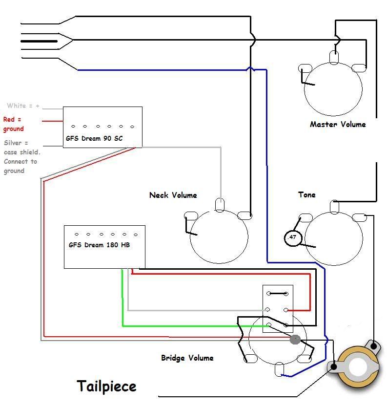 Btw, this is the guitar that is being molested.  EDIT I see I forgot to draw the ground from the 3 way switch to the back of the dpdt switch. That's at least one mistake in there! |
|
|
|
Post by ashcatlt on Mar 19, 2009 15:04:47 GMT -5
I'm not going to try to figure out the wire colors. As long as you've got that right, it looks mostly okay.
The master tone wants to be wired as a variable resistor, rather than a voltage divider. That is, you want the output to the jack connected to the wire coming from the master volume. You can leave it as is and add a jumper between the two right hand lugs, or you can move the wire from the right to the center.
You'd like to have the metal pickup covers connected to ground. If they have bare wire, this probably connects there somehow. You could check with a meter. Either way, the braided shield would be a great way to carry this connection to your ground point while keeping your shields and signal returns seperate till the last minute.
|
|
doc74
Rookie Solder Flinger
Posts: 8
Likes: 0
|
Post by doc74 on Mar 19, 2009 15:11:45 GMT -5
Ok, output jack wire goes to middle lug on tone pot, not on the right...that makes sense.
I think I have the bare wires from the pickups soldered to the braided shield right now. I thought I read somewhere that this was a bad idea, maybe I read wrong. I will give it a try.
Thanks for your input once again.
|
|
|
|
Post by gitpiddler on Mar 19, 2009 15:37:25 GMT -5
Welcome doc. A big +1 to keeping the signal grounds (returns) separate all the way to the jack. That little step is what improved my noise issues after 20 years of scratching my head over it. Sounds like a lot of work fishing thru the F-holes. Good luck, keep us updated.
|
|
|
|
Post by lpf3 on Mar 19, 2009 17:08:30 GMT -5
Doc - That's how I've been extending mine so far with no problems . I twist them together a little at the joint and ....... Ashcatlt writes ...... Yeah , like he said .  If you use the zipties you can actually form a sort of wiring harness & shape it so you don't have to see too much clutter thru the f-hole , that is if you have enough wire . Real nice lookin' guitar , BTW . -lpf3 |
|
|
|
Post by ashcatlt on Mar 19, 2009 21:36:31 GMT -5
Real nice lookin' guitar , BTW . Yeah, aside from the orange and the gold. |
|
doc74
Rookie Solder Flinger
Posts: 8
Likes: 0
|
Post by doc74 on Mar 20, 2009 7:01:18 GMT -5
Real nice lookin' guitar , BTW . Yeah, aside from the orange and the gold. Ha! I get that reaction from time to time but I can't help but love it. It is too decadent not to love  Regarding the push/pull....how do I wire it so the hb is in series with the switch in the down position and parallel with the switch in the up position? How do I look at the schematic, is this how it would be with the switch installed or is it upside down? It's tricky working through the f-holes. I use blue paitners tape to protect the edges from chipping and so far so good. The one positive thing about it though is that the entire harness is on a workbench away from the guitar, so no risk of burning the guitar's finish. On the other hand, to test the circuit I need to assemble the whole thing to see if it works. I bought a multimeter so I will try to figure out how the thing works so I can measure resistance...or something...I'm not sure how to test if it will be without noise before the wiring is in the guitar so I better do as good of a job I can soldering the whole bunch together. I checked my roll of wiring and it's 3 conductor with braided shield, the HB of course is a 4 wire....Would it be wrong for me to remove one of 3 so I end up with a length of 2 conductor wire? That way I can cut it in half and extend red and white with one piece and green and black with the other. I could connect the bare wire from the HB to both braided shields on the HB end and connect broth braids to the pot on the other end....boy this is confusing... |
|
|
|
Post by newey on Mar 20, 2009 9:40:51 GMT -5
Wouldn't be wrong, but wire is cheap, you could just leave the 3rd one unconnected and probably make your life a bit easier. You can test it to see that everything is working correctly out of the guitar, using your multimeter. But testing for noise will mean installing it in the guitar, since the bridge ground will need to be connected to give you any real idea of how noisy it may be. ChrisK's "Brain scan" technique can be used to test your completed wiring. In that link, the technique applies to an LP-type guitar, but the same principles can be adapted to your set-up as well. |
|
doc74
Rookie Solder Flinger
Posts: 8
Likes: 0
|
Post by doc74 on Mar 20, 2009 13:08:18 GMT -5
You're right, it makes more sense to just leave the 3rd wire unconnected. Yeah there's no easy way out here, I'll know if it's noisy or not when it's all installed Well I must say with all the help I'm receiving here I feel more confident and I look forward to getting this done. Hopefully I will have some results this weekend. |
|
|
|
Post by ashcatlt on Mar 20, 2009 13:17:25 GMT -5
The addition of the Master Volume complicates the Brain Scan procedure somewhat. Since you've got everything out of the guitar, you'd be better served to just measure the actual DC resistance of each component individually. Note that to get an accurate reading, the component you're testing needs to be disconnected from the rest of the circuit.
Read the resistance on each of the coils from one wire to the other. Read the resistance of the Volume pots across the 2 outside terminals. In either case, it doesn't matter which side gets the red probe. Keep track of these readings. Then we can predict the readings you'll find when it's all wired together, which will allow us to verify that everything is wired correctly.
|
|
doc74
Rookie Solder Flinger
Posts: 8
Likes: 0
|
Post by doc74 on Mar 23, 2009 6:14:53 GMT -5
It's done! After a bit of soldering and a lot of fishing, the wiring is back in it's place. I plugged in the amp cord and gave it a test run and at the time I thought it was working as it should...until I turned up the amp I have an older Fender Princeton chorus amp. It's a simple 2x10 55w solid state, nothing special about it but it gives a nice clean sound. I had it on two when I plugged in the guitar and it was silent, no static noises. Only when I turned it up did I hear that the ground problem still exists although it seems to be much less now. I then disconnected the amp and plugged the guitar straight into a Line 6 pocketpod. With some settings, like clean amps, the guitar is fairly silent. There is a difference when I touch any hardware or strings but it's so small that it's not very apparent. Only when I have a high gain setting on does it become noisier. At this time I'm going to leave everything as is. I don't know what else I can do. The good news is that the pickups sound great! By replacing the neck pickup pot I now have a brighter sounding pickup, no more mud! The series/parallel works great and the parallel hb in combo with the neck sounds sweet! Eventually I'll want to have this ground problem fixed but it's such a hassle navigating everything through f-holes I'm not up for it right now. I'm happy with the sound of the guitar and want to play it for a while before I start over again. I'm going to stick around here and learn as much as I can and maybe try to help someone out with the little knowledge I have. Besides....there's still that strat that needs some silencing... ;D This is the same schematic but I've added the shielding. The 3 way switch and master volume are the original, I did not touch that wiring. Maybe there's too much shielding soldered to the pots or maybe I have a cold solder somewhere. The bundle on the push/pull is kinda big.... 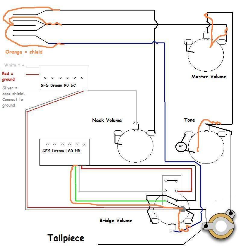 |
|


 If you use the zipties you can actually form a sort of wiring harness & shape it so you don't have to see too much clutter thru the f-hole , that is if you have enough wire .

