santellan
Meter Reader 1st Class

Posts: 63
Likes: 0
|
Post by santellan on Oct 19, 2009 16:00:53 GMT -5
I'm back. I am trying to combine an active bridge pickup with a passive middle pickup which will utilize an opamp circuit to allow it to combine with the bridge. I would like it to have the N, M and NM as passive maybe by using a switch to bypass the circuit. I am using a dual supply for now but could easily just use a single supply. This schematic is just a starting point for discussions especially in regards to the op amp. Pos 1 N with Tone control Pos 2 NM with Tone control Pos 3 M with Tone control Pos 4 M active with Bridge active no tone control pos 5 B active no tone control 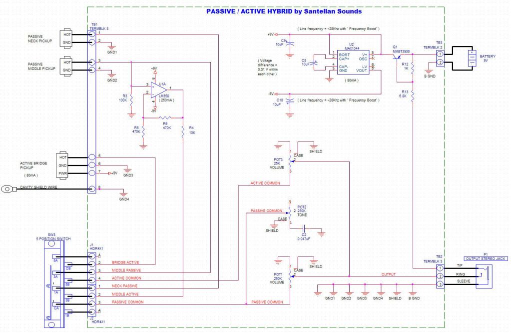 |
|
|
|
Post by newey on Oct 20, 2009 5:47:49 GMT -5
Santellan-
We're a pretty passive bunch here, we don't get many active circuits. And I'm certainly no expert on this stuff, so take this with a rather large grain of salt.
The opamp portion of the circuit looks ok to me. My only question is, what happens at position 3? The passive side of the switch (CA) is connected to output, while the B side of the switch connects the active mid circuit to the active bridge hot. I'm wondering whether this will generate noise and drain the battery?
Also, from a practicality standpoint, with two dissimilar active pickups at position 4 (and without a control to adjust the amount of boost on one or the other), isn't it likely the output of one will be greater than the other, leaving one hearing only the hotter of the two? A trim pot on the board to allow the user to dial in the relative boost of each might be useful.
|
|
santellan
Meter Reader 1st Class
Posts: 63
Likes: 0
|
Post by santellan on Oct 20, 2009 11:26:34 GMT -5
I assumed that since position 3 active side has no output then only the passive side would function.
Also since the active side has it's own volume control you should be able to set it lower than the passive volume control.
Anyway that's my thunking anyway.
Maybe we can get some interest from others in regards to active circuits since I have a 60hz filter and two preamp circuits ( 1 clean and 1 boost) I wouldn't mind sharing with the group.
LS
|
|
|
|
Post by ashcatlt on Oct 20, 2009 11:44:40 GMT -5
I'm a little concerned about position 4. Seems like you'll have both the Middle Passive and the Middle Active connected to the output. Assuming there's some gain in the opamp (looks like it's going to be greater than unity), it'd probably swamp the passive signal volume wise. Problem I see, though, is that the relatively low output Z from the opamp circuit will load down the middle pickup, leading to some pretty serious tone suck. This would affect both the passive and active signals from that pickup.
Maybe I'm missing something, though.
|
|
santellan
Meter Reader 1st Class
Posts: 63
Likes: 0
|
Post by santellan on Oct 20, 2009 12:32:48 GMT -5
I am concerned as well. I thought of using a switch to toggle between passive & active middle but I feel that in real use flipping the lever to position 4 and pushing a button may be too much.
What do you think?
Has anyone combine active with passive pickups?
LS
|
|
|
|
Post by sumgai on Oct 20, 2009 16:56:07 GMT -5
santellan, First Quick Glance: Right about now, I'd be more concerned that the player will get no output at all..... You show the TRS output jack as having the output going to the Ring terminal instead of the Tip. Somehow I don't think this gonna end in happy faces for anyone.  More in a few moments, as time allows. sumgai |
|
|
|
Post by sumgai on Oct 21, 2009 2:22:20 GMT -5
OK, a "few" hours later..... Lots of concerns, sorry to report. Let's get started, shall we? 1) The MAX1044 is rated to deliver up to 10mA of current in any configuration. Why'd you put down "(80mA)" on your diagram? My data source: datasheets.maxim-ic.com/en/ds/ICL7660-MAX1044.pdf (1st paragraph of the Gen. Desc.) Keep this in mind as we look at the next "chip". 2) The LM358 is a nice choice here, being low power and all, but it still requires a fair amount of current just to start getting the job done - as much as 20mA. Oops, right there we have a potential mishap. And that's before we hook up the active Bridge pup. You might consider stepping up to the MAX660 for up to 100mA of current capability. My data sources: www.national.com/mpf/LM/LM358.html and www.national.com/an/AN/AN-116.pdfIt could be argued that I'm looking at the max values on the charts, and you don't anticipate ever getting close to those values. And how many devices have I blown up lately, by taking a seat-of-the-pants guess at the "probable" performance numbers?  My feeling is that it's OK to blow something up in the experimental stage of things, but that it's not OK to have that same something blow up in the customer's face (figuratively speaking, of course). For the prices we're talking here, it's always better to play it safe, period. Chalk it up to "best practices", and call it a day.  2a) And for that matter, why are you using the MAX1044 to deliver a split supply anyways? You show the active Bridge pickup as using only +9 volts, so that's not the reason. And the op-amp is easily capable of running on a single input supply, so that's also not a good reason. From a valid design standpoint, it'd be loads cheaper to create a V r voltage for the input with two resistors than to use that inverter/converter/diverter/etceteraverter.... doncha think? Check out the Applications Notes pdf file, linked above, for some examples. 3) Contrary to popular belief, your switching arrangement on the "B" pole of the selector is workable, even if it's highly unorthodox. However, you should consider making arrangements for switching the phase of one pickup or the other - at this point, you have no idea how the Middle and Bridge pups relate to each other, phase-wise, and the user might end up with a tone they don't like. 4) The Middle passive and Middle active outputs will combine at the output jack, after the two volume controls. If both controls are at their maximum levels, then you are essentially feeding the output signal right back to the input of the op-amp.... I needn't tell you that this is a Cardinal No-No, right? The op-amp is configured for a gain of 2, and the signal returning to the op-amp's non-inverting input is in-phase, right? Well, those are the two main requirements for an..... oscillator! Can you spell howling guitars, boys and girls?  You can alleviate that by using the other half of your op-amp as a unity-gain buffer to isolate the Middle passive output from everything else. 4a) While I'm at it, what's that 10KΩ resistor doing in the op-amp's output path? That won't do any good for the signal, and if I'm not mistaken, the output is now unloaded (little to no impedance), which doesn't hurt the device any, but it does hurt the signal's harmonic content, I'm quite sure about that. That 10KΩ resistor should be going to from the output pin to ground, to keep the amp's output properly loaded. (Again, I cite my source pdf file, linked above.) 5) Just like a Les Paul, if you turn the either of the volume controls all the way down, or nearly so, you'll kill all output signals, period. I'm sure you can figure out the cure for this one, right?  6) My only suggestion is that a superswitch would allow you to shunt the Bridge active pup with a resistor such that in position 4, the Bridge volume is reduced to approximately the same as that of the Middle pup. When switched to position 5, the shunt is removed and the Bridge pup puts it out loud and proud. While this goes to making things cheaper and even more reliable, it also addresses all the above issues too. Just something to consider, in your spare time...... ;D HTH sumgai |
|
santellan
Meter Reader 1st Class
Posts: 63
Likes: 0
|
Post by santellan on Oct 21, 2009 12:10:08 GMT -5
Sumgai, Are you saying that with a superswitch and a resistor it would let me combine the passive middle and active bridge pickup in a useful manner? Would I still need 2 volume controls? LS 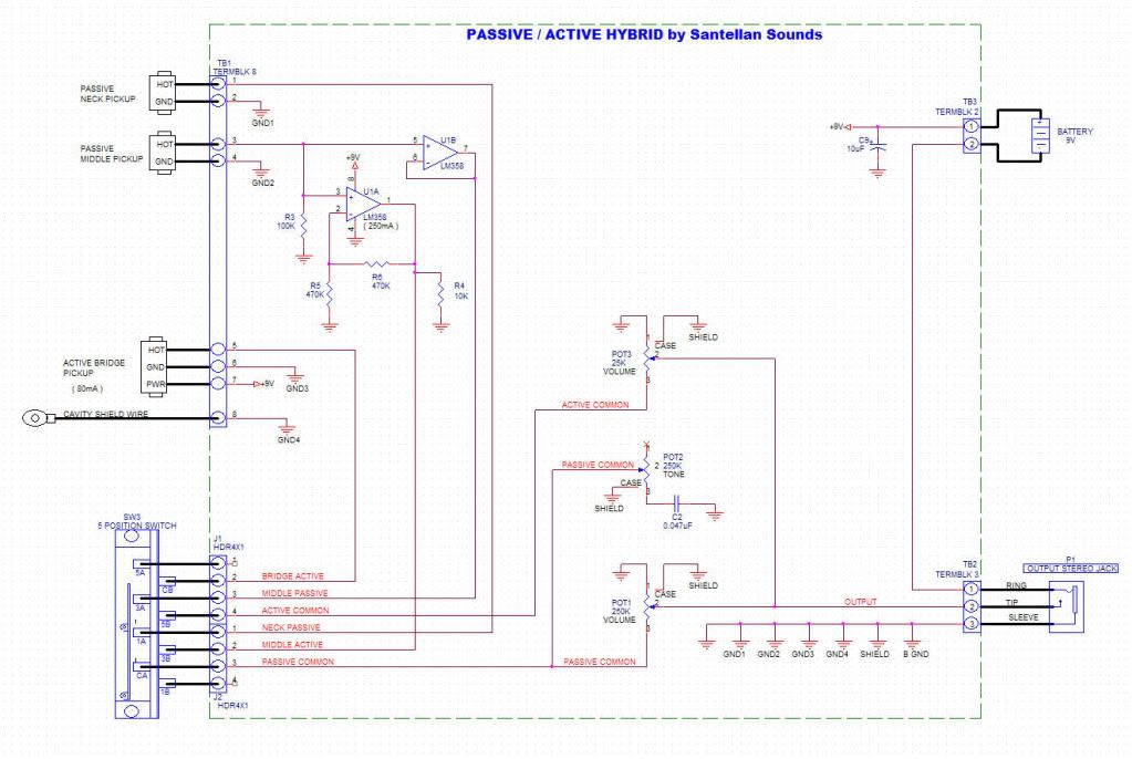 |
|
|
|
Post by sumgai on Oct 21, 2009 14:24:26 GMT -5
santy, Need two volume controls? Yes. Have to have both of them user-accessible? No, not unless you wish to. One could be a mico-pot on the board, whereby the user sets the balance desired, then buttons it up. From that point on, the master volume control on the outside of the pickguard is all that's needed. But putting both outside is OK two, so long as the user understands the operation of the controls. BTW, I missed it last time, but you've got two R5's, both of them being the feedback loop voltage divider. You also need to create a V r for the input terminal. Since you already have R3 going to ground, you need only connect another 100KΩ resistor going to +9v, and you're all set on that score. If you're planning on supplying all the pickups in the set, and the customer doesn't get to play around with his own pups, then I can see where you'd make sure that they're all in phase before you shipped it - no phase-reversal switch needed. But if you're giving the customer an option to use his own pups, then you might consider the addition of such a switch. You still have the issue of one volume control killing everything if it's turned down all the way. But then you were perhaps waiting on my answer (above) about having two controls..... The unity-gain buffer looks good to go, that should resolve any issues of possible oscillation, or other harmonic impurities. Reversing the labels of the TRS jack was a good start, but now the labels don't match the actual drawing. Might confuse some folks, but since I'm the one that pointed it out in the first place, I knew what you meant. Remember, there's no crime in having lines cross each other - it's only a schematic.  That's all I can think of for now. Keep up the good work! HTH sumgai |
|
santellan
Meter Reader 1st Class
Posts: 63
Likes: 0
|
Post by santellan on Oct 21, 2009 18:26:34 GMT -5
Sumgai, The idea behind this schematic was to be able to use your own passive pickups and add an active EMG or SD Blackout bridge pickup to your guitar. Do you think a treble rolloff circuit would still work? 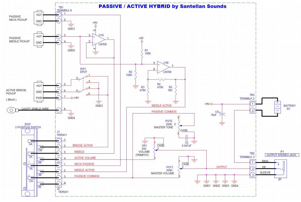 |
|
|
|
Post by sumgai on Oct 22, 2009 0:41:57 GMT -5
santa, The circuit just above looks pretty good, and after considering a few points below, it's pretty much ready for testing with real-time users! Having seen the active Bridge pickup with its phase switch, I just realized..... is that thing designed to have the ground connection share both the signal and the power paths? I can see where if the pickup depends on having +9vDC on the power pin, and the effectively negative side of the power supply on the ground pin, then I was wrong to suggest that you reverse the signal leads for this pup. If the pickup doesn't care which signal lead is grounded, it'll still work, then keep everything it currently sits. But if the signal leads can't be reversed (the pup no longer works), then you'll have to invert the phase somewhere else. Sadly, you now have the case of where if you invert the phase of the Middle, then it's also OoP with the Neck. A more intricate switch takes care of that, but it's still a pain (and not as cheap as your DPDT). Some bench testing is needed here, I'm sorry to say. The only issue I see now is even easier to deal with. The so-called "Master Volume" control isn't - the "Trim" control is still independent of the Master, meaning that either one will control only what comes into it (active to active, passive to passive) - the master will never be able to turn both circuits up or down at the same time. Run the output (wiper terminal) of the "Trim" into the hot terminal of the "Master" and then the labels will be correct, and all will operate as the user expects (from reading the instructions, of course  ). At that point, of course, you can choose to leave the Trim pot exposed for constant manipulation, or you can bury it - make it a "set it and forget it" control, and make the user's life even easier.  A couple more suggestions to ponder: If you search around, there are low-power versions of the LM358 available. Might make a marketing point to be able to claim that a battery will last 4 months between changes (or whatever your testing reveals). The other thing is, since you now have two out of the three pickups "active", why not include the Neck pup, and be done with it? That way you no longer have the crapacitance issue (crummy cables robbing tone, etc.) and making sure that all three signals are about the same level gets pretty easy. A summing circuit, enlarging on the current unity-gain buffer, would be easy to lash up. Check the Application Notes I linked earlier, I remember seeing such a circuit in there. HTH sumgai |
|
santellan
Meter Reader 1st Class
Posts: 63
Likes: 0
|
Post by santellan on Oct 22, 2009 15:00:40 GMT -5
Ok here's the updated schematic with your final comments. Sumgai can you draw up the superswitch version with the resistor shunt? Thanks, L 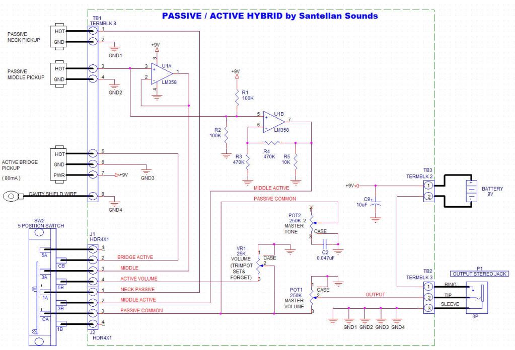 |
|


 My feeling is that it's OK to blow something up in the experimental stage of things, but that it's not OK to have that same something blow up in the customer's face (figuratively speaking, of course). For the prices we're talking here, it's always better to play it safe, period. Chalk it up to "best practices", and call it a day.


 ).
).