biggles
Rookie Solder Flinger

Posts: 14
Likes: 0
|
Post by biggles on Dec 3, 2009 22:29:19 GMT -5
But it's true, I have a Motherbucker, and predictably I'm unsure of how to wire it.
I've had it wired in one of my guitars before, I found a simple diagram and I personally love the sound of it.
I can handle any soldering situation, I do a damn good job I'm just not up to scratch with wiring knowledge, normal pickups I can do, but when it gets to switches and extra wires I'm unsure.
Basically it's going in an Explorer with an Invader in the neck, I would get a better pickup for neck tone but I'm ridiculously short on money.
I don't have any experience playing guitars with parallel or phase switches or anything like that, so I don't know what I want my switches to do.
I want the MB with two switches, I have one DPDT and a push pull pot, preferably using the push pull as the MB volume, a master tone pot, the Invader having it's own volume, and a 3 way pickup switch.
I'll be so grateful if someone is actually kind enough to provide me with a diagram or a good explanation of exactly what does what when wiring switches, as being able to make up my own switching methods like most of you seem to do is merely a dream for me.
|
|
|
|
Post by newey on Dec 3, 2009 23:54:36 GMT -5
Bigs- You said: This leaves the field pretty wide open- and makes it difficult for anyone to suggest something specific for you to do. In the end, you could have hundreds of wiring diagrams suggested to you, without you being able to discern whether they would really be to your liking or not. First, spend a bit of time learning some basics of guitar wiring- like how switches work and how they can be wired. Our member wolf's website has a good basic explanation: www.1728.com/guitar.htm(I know, homework . . . sorry!  ) Second, you need to ascertain the wiring color code for this pickup. The Motherbucker is nothing more than 2 SC-sized dual-rail pups stuffed into a single HB mounting. You have 4 coils to work with. Each pair of coils makes one humbucker. Each pair has a cable with 4 colored wires, plus a bare "shield" wire that is always wired to ground. According to the Kent Armstrong website, the 4 colors are red and green to one coil, black and white to the other. Unfortunately, they don't say which wires go to which coil. This can, however, be ascertained through some testing. You'll need to know which wires go to which coils in order to do anything more than basic wiring schemes. It is also likely that this info is on the web somewhere, I didn't search far and wide. Also, we can probably eliminate some ideas to narrow the field somewhat. For example, because the 4 coils are all in the same mounting, close together, you probably don't want out of phase sounds (OOP). These are more useful when the 2 coils being put out of phase with each other are widely spaced, like the neck and bridge pups are. With coils close together, putting them OOP results in a very low output, "tinny" sound that's not of much use for anything. While you might want to consider using one of your switches to put the whole Mother out of phase with the neck, I don't think phasing between the MB's coils is something you'd want. Recognize that you have 2 humbuckers in one, and you can see that you can use any wiring scheme for a 2 humbucker guitar. Or find a 3-HB diagram, and wire it with the neck as 1 HB and the Mother as the other 2. Once you've pondered all that a bit more, and can give us some more specifics, we'll be happy to help with a particular diagram or scheme. EDIT: Also, if you've never played a guitar with series/parallel wiring, or split-coils on a HB, a quick trip to your local guitar store can remedy that. Ask to play a Baja Tele, or a Strat with S-1 wiring- these have series/parallel options. While they won't sound like your guitar, it would at least give you some idea of the sounds that are possible. |
|
biggles
Rookie Solder Flinger
Posts: 14
Likes: 0
|
Post by biggles on Dec 4, 2009 0:10:22 GMT -5
Thanks for the informative reply, yeah I know all about the pickup etc and which wires are which, I just want a diagram of how to wire it in with another pickup using a pickup switch, cause the few I've tried haven't worked for whatever reason.
Something simple like using one switch to tap it and the other for series/parallel would be ideal, just something so I can get the Explorer working, it's my most used guitar and having it sitting with it's wires hanging out is annoying even for this one night.
|
|
|
|
Post by dunkelfalke on Dec 4, 2009 1:21:21 GMT -5
With coils close together, putting them OOP results in a very low output, "tinny" sound that's not of much use for anything. Now series has got nice woody sound in it. Gorn! (sorry, just couldn't resist) |
|
|
|
Post by wolf on Dec 4, 2009 3:58:02 GMT -5
Thanks newey for the good words about my website. Biggles, do you have any wiring diagram available to you? As newey said, just asking for a wiring diagram isn't enough. The motherbucker by itself is equivalent (in terms of wiring a circuit) to two 4 wire humbuckers. If you aren't aware of how much tone options that offers, here is a page on my website for what I call Super Seven Switching which gives you 40 tone options. www.1728.com/guitar6.htm(In your case it would be a "mere" six switches because you wouldn't want the phase switch controlling 2 coils so close together the same pickup). Anyway, since you said you want to rewire your guitar, just what exactly do you want? |
|
biggles
Rookie Solder Flinger
Posts: 14
Likes: 0
|
Post by biggles on Dec 4, 2009 4:39:07 GMT -5
Wolf, I have literally one or two motherbucker wiring diagrams, but they only deal with the motherbucker, not any other pickups or anything.
And I believe you missed my second post in this thread, for the minute I just want to get it all together and get it working, so just the plain coil tap and series switching is all I require, I'm just itching for a diagram that'll definitely work so I can have the setup I want.
|
|
biggles
Rookie Solder Flinger
Posts: 14
Likes: 0
|
Post by biggles on Dec 4, 2009 10:39:25 GMT -5
Ahh please tell me someone can help, this is really pissing me off now, I can only find two diagrams on the whole internet that use two switches, another that uses 3 but I can't do that cause I don't have a third switch.
I just want to get it wired up working, with split and parallel switches, nothing too fancy, I just want to play my damn Explorer!
|
|
biggles
Rookie Solder Flinger
Posts: 14
Likes: 0
|
Post by biggles on Dec 4, 2009 12:27:16 GMT -5
Ok so I've just wired this up cause I just couldn't wait for anyone to reply, and it still doesn't work. Obviously I have an Invader in place of the P90, I imagine it would work the same way just using the hot output from the Invader.  It works, in that I get a guitar sound out of my amp, but even with the distortion right up it's a muddy clean sound, so obviously there's something wrong somewhere, and it does the same thing for both pickups, it's seriously getting me wound up that I can't get the damn thing to work, someone please solve something for me! |
|
|
|
Post by wolf on Dec 4, 2009 15:38:16 GMT -5
Hello again Biggles
For one thing are you absolutely sure of the wire colors and which goes where?
Who is the manufacturer of the Motherbucker? (Kent Armstrong? Mighty Mite?)
If the tone sounds bad are you absolutely sure that everything was wired and soldered correctly?
|
|
biggles
Rookie Solder Flinger
Posts: 14
Likes: 0
|
Post by biggles on Dec 4, 2009 16:49:27 GMT -5
Yeah I've found the original instructions that come with the pickup so I know the wire colours, and trust me man I checked and double checked it so many times!
It's really confusing me, cause I've never had wiring not work this badly before, as in taking this many attempts!
I'm not so bothered that the ones I've found myself haven't worked, cause they weren't the setup I originally wanted, if one of you guys draws one up for me and it doesn't work, then I'll have to start investigating the integrity of all my components I guess, which I'm pretty sure are all in fine working order.
|
|
|
|
Post by wolf on Dec 4, 2009 23:43:47 GMT -5
Looking at the diagram, the P-90 pickup only shows 1 wire exiting from it. It also shows that same wire being connected to ground and connecting to the pickup switch which would be considered the "hot" side of the circuit, producing a dead short.
Yes, I know you have an Invader in place of the P90 but if you followed your diagram exactly, the circuit would have problems.
So, how did you connnect that second wire. (Yes, an Invader has 4 wires but we will assume the correct two have been connected and soldered).
|
|
|
|
Post by wolf on Dec 5, 2009 3:43:17 GMT -5
Okay Biggles, I'll reply yet again. I redrew your diagram because I thought it was a bit too big (plus that P-90 needed another wire). Also, I did not draw the volume and tone controls because even though that might be your problem at the moment, these controls have no effect on series / parallel / coil-cut arrangements. Another thing to get out of the way were those fancy switch drawings. So here's my version of that circuit:  Not that I wanted to make my own diagram, but isn't it easier to discuss this "hot-rodded" diagram? I was just curious if you know what this circuit is actually supposed to do? Basically, it is using one SPDT center on switch (right side) to choose the P-90 on its own, the MotherBucker on its own, or both pickups in parallel. The left side switch is used to choose the top or bottom coil of the mother bucker and the mid position selects both. Incidentally it seems the Mother Bucker is wired to be in parallel even when both coils are on. I believe this was done so a player could have this tricky little arrangement. (Either coil seperate or both coils in parallel. Only problem with this is that with humbuckers, if you had to make a permanent wiring choice, they are almost always wired in series. Another interesting point is that when both neck and bridge pickups are on, a humbucking arrangement will occur when one of those coils are chosen. |
|
biggles
Rookie Solder Flinger
Posts: 14
Likes: 0
|
Post by biggles on Dec 5, 2009 7:54:52 GMT -5
Oh man thankyou so much for drawing something at all! I'm heating up my soldering iron as we speak.
What you've drawn is just right, it's exactly what I wanted except for the P-90, am I right in thinking I can use the hot output from the invader in place of the wire from the P-90 and if I remember correctly I should ground the bare and green wires and tape off the red and white?
|
|
|
|
Post by newey on Dec 5, 2009 9:17:25 GMT -5
That depends on the color coding of that pickup. Do you know the color coding for that? (We haven't discussed the Invader pup yet).
Does this mean that both pickups operate and that the switches operate as they should? (Use the Screwdriver tap test to ascertain this). If so, I tend to agree with wolf that the problem may lie in the vol and tone circuit.
|
|
biggles
Rookie Solder Flinger
Posts: 14
Likes: 0
|
Post by biggles on Dec 5, 2009 11:02:12 GMT -5
Ahhhh Wolf I wired up your diagram and it didn't work. I checked it so many times, and when I plug it in I get no sound at all, not even a faint signal, I just get the odd buzz or pop from moving the switches, and no combination of the two switches does anything. So I reckon by elimination that I must be much worse at soldering than I first thought haha, so I've taken some pictures, tell me if you spot anything wrong with them. This one is the switch arrangement, as you can see on the left switch I have the hot from the Invader where it should be. Then the bluey green wire connecting the other side of the switch to the middle of the second switch. The two curled white wires are the grounds from both switches, and all grounds go to the long thick grey cable along with the hot output from the switch, to the cavity. And of course both black outputs from the Motherbucker to either side of the switch on the right, as they should be. 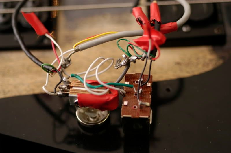 And I opted for just one volume, to make it easier to get right. The two black cables to the back of the pot are obviously the ground from the bridge and the other is the grounds from the switch area. The white cable is the output from the switches, and the blue wire is to the output jack. 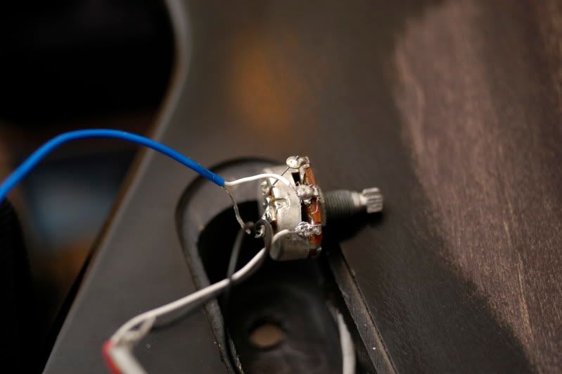 Now as far as I can see, I've checked everything many times, and I can't seem to see anything wrong, is it my wiring? am I blind and missed something? |
|
|
|
Post by wolf on Dec 5, 2009 13:39:46 GMT -5
If it is a Seymour Duncan Invader the color code for that is:
White & Red soldered together, connected to nothing else
Black - Hot connection
Green - Ground
|
|
biggles
Rookie Solder Flinger
Posts: 14
Likes: 0
|
Post by biggles on Dec 5, 2009 14:33:06 GMT -5
Yeah that's how I did it, can you see anything wrong in the pictures I posted?
|
|
|
|
Post by sumgai on Dec 5, 2009 15:44:41 GMT -5
biggles, Assuming that you've got the color codes correct, do this: 1) Desolder both pickups from their switches; 2) Desolder the output jack from anything else; 3) Solder one pickup directly to the output jack, and test with your amp. No go? Bad berries.  But at least you know what to do. 4) Lather, rinse and repeat with the other pickup. You just boiled it all down to nothing but the two essential components - the pickup and the output jack. If that doesn't work, then your pickup(s) is/are bad. I suppose the jack could go south on you, but normally you'd be able to see that with your eyes, meter readings optional. If one of the pups is bad, then stop now and report here what you found, we'll deal with the issue before going any further. But if both pickups give you sound from the amp, start working your way backwards, step by step: Using the Invader to start with (because it has only one hot lead to deal with, instead of two), hook up the volume control between the Invader and the output jack. If that works, insert the tone control (both the pot and the cap) into the circuit. Still working? Good. Insert the pickup selector switch, wiring it exactly as you would normally. (Ah ah ah! I mean, wire up the switch into what you already have put back together - don't get ahead of yourself - leave the MB and its switch alone for a bit longer.) The switch should function as expected. Before you go any further, test both sides of the switch by moving the pickup's lead to the remaining side. Now, let's hook up the MB. Using just one coil (one of the black leads), hook it to the switch. Everything still fine? (Maybe a touch weak on the output, but so what.) Now take that coil off, and replace it with the other MB coil's black wire. And what did you get? Probably the same thing, all OK. (After all, you did test each individual coil with just the output jack, and they worked there, right?) Time for the final switch insertion. If you haven't already done so, desolder the MB's hot lead you tested with, and hook it up to the MB switch. You might as well hook up both of them now, I suspect that unless the switch has a really hard-to-spot malfunction, then it's probably going to work. And hook the MB switch into the main selector switch, as before. You've now completely rebuilt your circuit, from the ground up. The only thing left to do is test to be sure the MB switch works to select one or both coils, and you're done! ;D Feel free to stop anywhere along the way, and ask questions if something is bothering you. ;D HTH sumgai |
|
biggles
Rookie Solder Flinger
Posts: 14
Likes: 0
|
Post by biggles on Dec 6, 2009 9:41:19 GMT -5
Sumgai, everything works perfectly up until I start adding the switches in, I don't know enough about switches to know what the hell is wrong with them, But I'm seriously sick of it now, and to make it worse just wiring both the hot outputs from the motherbucker to the jack won't work, it's still only a quiet, cleanish signal so I can't just play the damn guitar with one pickup.
|
|
|
|
Post by sumgai on Dec 6, 2009 13:36:24 GMT -5
biggie, While your report is terse, I think we've got enough to get a good start. It would seem that the Invader works when going directly to the output jack. It also seems that the MB is Ge-Fooey, right? Well, that indicates only a few possible faults. Let's do this: Ooops, I gotta first ask - you have a multimeter, right? Either digital or analog, it doesn't matter, but being able to take measurements is critical at this point. If you don't have one, go get one. Even a $9 cheapie will do for what you need. (But a more robust $30-50 meter would be better in the long run, for lots of reasons.) Now, use the meter to verify each of the coil connections. I'm thinking that at least one of those four coils is somehow bad. You should be able to see at least 4 to 6KΩ for each coil, and possibly up to 8KΩ. If you read nearly 0Ω, that coil has become "shorted out", and requires repair. If you get nothing (the display reads "OL" or "OR" or some value way above 20K&Omega, then your coil is probably open (no continuity), and that also requires repair. Once you've figured out there's a bad coil (or more than one), then you can decide to either: 1) fix it yourself (not recommended for the faint of heart); 2) have someone else fix it (might be a tad expensive); 3) have it fixed under warranty (a good idea); or 4) just replace the thing. That all will depend on your warranty status, of course. If you're in a hurry, you might replace it now, and worry about fixing it later. (Then, you've got a spare, or trading material, or you can craigslist it for cash.) All of that assumes, of course, that you find a bad coil. If the meter tells you that everything is copacetic in coil-land, then you've got other issues. At this point, I'd suspect that the wiring color codes are not correct as you've been told, but keep in mind that I'm not an expert on MotherBuckers (nor on humbuckers in general), so I may be out to lunch on that WAG.  Which is why I (and the rest of us Nutz) value a meter so highly - it tells the truth, every time.* Awaiting your answers..... (We'll deal with your switching-phobia after we have something worth switching.  ) sumgai * Well, providing the meter's internal battery is still good!  |
|
biggles
Rookie Solder Flinger
Posts: 14
Likes: 0
|
Post by biggles on Dec 6, 2009 13:46:57 GMT -5
I never said the MB wasn't working? it works fine when wired straight to the jack.
I dare say it may be something to do with the diagram, cause I've got 6 or 7 different switches lying around and I tested them all as part of the component test and they all work, and as I said both pickups are working, either pickup with a volume pot works, and my pickup switches work, but that wiring diagram Wolf posted doesn't, and neither does any diagram I've found online.
|
|
|
|
Post by wolf on Dec 6, 2009 17:30:28 GMT -5
Biggles, you said If it is a "quiet, cleanish signal" does that mean you think the sound is quieter than what you think it should be and this is creating a problem? You really should be more specific in your descritptions. Just to make things very simple, I decided to redraw my own diagram.  If you want to try this circuit, you'll have to do a minor wiring change to the Motherbucker, but you'll have a 2 pickup guitar. |
|
biggles
Rookie Solder Flinger
Posts: 14
Likes: 0
|
Post by biggles on Dec 6, 2009 22:21:00 GMT -5
I'm sorry to say you guys can ignore this thread now, I've opted not to use the Motherbucker.
I had an old Ibanez INF3 humbucker lying around so put that in the neck and the Invader back in the bridge with a coil tap and phase switch, and it sounds sweet as hell.
I'm just gonna sell the Motherbucker as I still have the original box, and use the money to put towards buying myself a Bare Knuckle Warpig, my favourite pickup that I regret selling, thankyou for trying to help though!
|
|


 )
)


 But at least you know what to do.
 )
)