Raz59
Meter Reader 1st Class

Posts: 71
Likes: 0
|
Post by Raz59 on Apr 19, 2010 23:04:13 GMT -5
That suggestion seems fine by me, John. If you wouldn't mind changing the schematic to reflect that, I'd be very thankful.
Although for me, ideal would the ability to connect both screw coils (in series or in parallel)...I relate that combination to a twangy sound, I'm not sure if that's achieved with the bridge slug coil and the other neck coils.
But like you said, if the bridge is uncovered, both coils ought to sound the same, so I'll put faith in someone's better judgment.
And I'll eagerly wait for (possibly) next weekend! I still have to buy some Alpha DPDT push/pull pots and convert my pickups from 2 to 4-conductor wire, so there's still stuff on the "To Do" list.
Does anyone mind if I go off-topic for a bit? I have some questions.
Has anyone ever tried applying a No Load mod to a push/pull potentiometer?(I'm planning to do so, for the tonal benefits)
Should I do it for this wiring?
Why should I only apply the No Load mod to the volume controls and not to the tone controls?
|
|
|
|
Post by JohnH on Apr 19, 2010 23:31:09 GMT -5
Raz – I don’t advise trying to open up a push/pull pot, nor do I have any idea how to without wrecking it! It is too complex and usually the pot is a 16mm size, not as robust as a full size 24mm. I've had good success doing various track cutting operations with standard 24mm pots however, with no failures yet.
Also, no-load pots only work on tone controls, because you cut the track before it reaches the end of its travel. Volume pots would not work. I advise 500k audio taper pots for all four on this design – they work well.
If you are adding wires to your pups to make them four conductor, will you follow the Seymour Duncan colours? – I’ll assume so, or at least for the diagram. I converted my Gibson HB pickups lke this, and used a shielded 4 conductor wire, with yellow in place f green.
If you were not opening up your pickups, then for reasons above, you could not get both screw coils in a humcancelling in-phase combo. However, to take a further step, if you are doing this, you can reverse one magnet and make this possible, which I did on mine. Interested? If it is an alnico bar magnet, swap it so the two long thin edges reverse position, on one pup only, and state which one you do it to. Then, when you select two screw coils, one will be a north coil and the other a south, and you can have them in phase and humcancelling.
cheers
John
|
|
Raz59
Meter Reader 1st Class
Posts: 71
Likes: 0
|
Post by Raz59 on Apr 20, 2010 7:26:30 GMT -5
No Load mods can't be done on push/pull pots? Oh woe is me... I will try to follow the Seymour Duncan color code, yes. I'll try to buy 60 cms of this wire:  You want me to flip a magnet? I can do that sure, I did try doing it that to the magnet on the bridge pickup once, but I must have flipped it the wrong way. For the record, I'll be flipping the bridge magnet, unless I'm told not to do it to that pickup. And I just realized...I'll have to remove the cover and the wax potting on the neck pickup as well! Let me guess John: you want me to put one pickup magnetically out-of-phase with another and then correct the phase electrically using the phase switch's down position? In theory that should work so I'm guessing that's what you'll do. This is becoming quite the exotic wiring. |
|
|
|
Post by JohnH on Apr 20, 2010 15:42:48 GMT -5
Thats about right. When you are done with rewiring/flipping the pups, and before you put them all back together, Id suggest placing the two pups face to face to make sure the two screw coils are now magnetically attracted to each other, to show that they do have opposite polarity (also do that before you start, they shold repel), and just check with a meter or by connecting the leads to an amp, that the wires are going to the coils that you expect.
John
|
|
Raz59
Meter Reader 1st Class
Posts: 71
Likes: 0
|
Post by Raz59 on Apr 21, 2010 22:21:41 GMT -5
Thanks for the tips, that polarity check trick will come in handy. And by the way, since the wiring will be using treble bleeds: I stumbled upon this video and it reports a problem when tying together more than one volume pot. Am I to expect this effect on the new wiring or is it something unrelated to it? |
|
|
|
Post by sumgai on Apr 22, 2010 3:48:11 GMT -5
Raz, I'm not sure just what circuit design you'll finally settle on, but that fella's problem stems from the fact that he's using what we call "reverse wiring". That's where the pickup's hot lead is hooked up the pot's wiper, instead of where it belongs, on the high side of the pot (with the wiper going to the output). Redraw his diagram with the change I've just noted, and you'll see that his "issue" goes completely away.  HTH Also, note that I've forcefully fettered my opinion of his recording techniques.  sumgai |
|
|
|
Post by JohnH on Apr 22, 2010 8:39:09 GMT -5
As sumgai says, he had a bad circuit design. On the other hand, you will have a good circuit design, which will therefore be better.
That problem will not be evident.
|
|
|
|
Post by JohnH on Apr 23, 2010 20:29:56 GMT -5
OK - try this!  Its a combination of the London underground and the bag of random wires at the bottom of my spares box! Seriously....I think its all there. As you can see, it is not a simple build. It will need another check to confirm its all OK, its easy to make an error in a layout like this. But i hope you like it. John |
|
Raz59
Meter Reader 1st Class
Posts: 71
Likes: 0
|
Post by Raz59 on Apr 23, 2010 23:08:40 GMT -5
First things first: John, I cannot thank you enough for the help you have given in my request, it could not have come this far without your contribution! Now for my very first reaction when seeing the diagram:  I've already bought the four 500k DPDT push/pull audio taper potentiometers and 60 cms of 4-conductor wire, I think that's length enough to be used on the pickups' conversion. And due to the complexity of this work in terms of soldering, it's best I give that work to a more experienced technician, lest I burn a pot or the coil wire itself. I will be measuring the potentiometers in order to match the values as best as possible. After the measurements, I'll be writing the respective values and names in accordance to the diagram (S1 through S4) with a permanent marker. So, given the fact that I'll print and hand this schematic/diagram out to a local luthier, I'll omit the pickup conversion notes and just add text specifying the color scheme I want - Seymour Duncan, right? The orange wire coming from the pickups represent the bare wires, right? I got a bit thrown off at first glance - and I'll specify the rotation of the bridge magnet. My dream wiring is almost coming to fruition! |
|
|
|
Post by JohnH on Apr 23, 2010 23:44:22 GMT -5
Yes its a bit shocking isnt it? It becomes somewhat of a rats nest due to the many interconnections between the controls, a few more even than a standard JP mod.
If you are studying electronics, your homework is to trace through the wiring and see if you agree if it matches the schematic, and workout for yourself if you think it will work!
The thick orange/brown wires represent the bare shield wires inside the cables, and get grounded. For grounding, I have made use of the grounding tab that you will see at the top of your push/pull switches. Its much easier to solder to this than to a normal pot case.
I would proceed with this design by first doing all the interconnects between the switches and pots, maybe with them mounted off the guitar on a card template. Then drop the harness in and connect on the pickup wires and toggle switch wires. - job done!
You are at liberty to join linked nodes in a different order, if you think that makes for neater wiring - guitars are not really sensitive to this, despite some who worry about ground loops etc. In general, the shortest wiring will be best.
Also note how the wires up to the main toggle and back to the jack are shielded - I think that is a good idea on an LP.
As to the pickup conversion, yes it is supposed to be Seymour Duncan, and should match my inset diagram. Please check this too. If you can get this design into your head, you will learn much that will help you, and you will be better able to trouble shoot it. I have never once built anything that worked perfectly first time!
John
|
|
|
|
Post by JohnH on Apr 24, 2010 20:47:16 GMT -5
Thinking further on how to build this - the stage by stage approach is definitely the way: 1. Convert the pickups and install 2. Lay in the wires from the main cavity up to the switch cavity and connect to the main toggle 3. Preassemble the control harness, off the guitar 4. Install harness, and connect pickups, jack and switches Each of those stages on their own is not too complicated, and to help Stage 3, here is a view of it, with no pickups or other connections attached:  I think that is looking much less scary? You could do that? cheers John |
|
Raz59
Meter Reader 1st Class
Posts: 71
Likes: 0
|
Post by Raz59 on Apr 24, 2010 21:22:20 GMT -5
John, thank you very much for helping out but you don't need to do any more diagram work for me!
If the soldering job were up to me, I would do it like you described:
. Build a template out of cardboard and trace the potentiometer and jack holes;
. Mount the pots and jack, do the connections between pots/caps/jack;
. Mount the pots back to the control cavity and do the remaining connections for pickups/switch.
It's not exactly planning that I'm lacking; the guitar was a gift and the ones who gave it don't want me with a hot iron near it so they're willing to even pay the luthier for the wiring deal.
It's also important to mention that if I went ahead with this, it would be my first soldering job - until now I've only handled breadboards, tension/current/function generators and O-scopes - soldering is a skill I've yet to acquire.
So it's not about my will to do it, it's out of respect for the people who gave me the instrument, I already do my share of tinkering on the guitar with string changes, bridge adjustments and finish dulling.
Again, I appreciate your help and am extremely thankful for the full diagram that has been posted, I hope you understand where I'm at right now.
|
|
Raz59
Meter Reader 1st Class
Posts: 71
Likes: 0
|
Post by Raz59 on May 28, 2010 15:33:07 GMT -5
After a month of gathering all of the new materials for this project (new jack and switch, potentiometers, pointer washers), the guitar is finally done. But...like all good experiments, there is always something wrong!
Now, I already made sure that the pickups are magnetically out of phase with each other. I checked this using a compass - screw coil on neck pickup repels the needle and the screw coil on the bridge attracts it.
First thing that I've noticed. The S2 (phase switch) is almost redundant...I always get the typical nasaly out-of-phase sound when the outputs of both pickups are matched, regardless of S2 being pulled or not.
Then there's another problem. I get very low output from the neck pickup when all switches are down...and when I pull S3 to coil-split this pickup, it actually increases the output and decreases hum.
Which suggests that either the switch is wired backwards or that there's loss of signal when in humbucker mode. I am inclined to believe that it is wired backwards.
And when I pull both S3 and S4, I am not getting the sound of a single coil on the bridge pickup...on the contrary, I am getting the sound of a humbucker...and it IS the humbucker, because if I push S4 back, the sounds are the same. Which means I can't split the bridge humbucker.
And with the current wiring, touching the cover and adjustment screws on the neck pickup, pronounces the ground hum...
Other observations include that the pickups clearly have a pronounced clarity right now...and when the bridge humbucker is switched to parallel, the resulting sound is so thin and trebly! It reminds me of a Telecaster!
So right now, only S1 and S4 (Master Series/Parallel, Bridge Series/Parallel) work as predicted. I am asking for help to those more observant than me: is this supposed to happen, given the supplied schematic, or does it mean that my guitar has some cold solder joints or something similar?
|
|
|
|
Post by JohnH on May 28, 2010 16:17:26 GMT -5
Something or things are amiss, and I suggest a methodical test program to find out what before jumping back into reworking the wiring. 1. Check magnetic polarity with a compass (Done! - you get a tick for that one - as intended for this diagram, the pups have opposite mag polarity) 2. Check resistance using a multimeter set to 20k or 200k Ohms range, clipped across a jack cord plugged into the guitar. Check and record resistance for each of the 16 settings of the push/pull switches. All volumes and tones should be at maximum for this. A single pup in normal full humbucker mode should be around 7-10k. Two such pups in parallel will be 1/2 of this. a single Hb with its coils in parallel will be 1/4, two Hbs in series will be x2 etc. 3. Change to a 200k setting select one pickup (ie normal system parallel mode) and gradually turn down its volume control. The resistance should rise from the pup resistance (say 7-10k), up to just over 1/4 of the volume pot resistance (say about 130k) then fall to zero with volume at 0. Check that turning tone pots have no effect on resistance. Repeat for each pickup 4. Set to 200 ohms range, and check resistance from bridge/strings to jack sleeve. It should be just a few Ohms to confirm strings are grounded. 5. Check which coils are active in each setting by tapping on a pickup poles while plugged in to an amp. Note that when only one coil of an Hb is selected, you may still get a reduced signal from the other coil due to magnetic coupling 6 Test phase in each setting, using a 'screwdriver pull-off' test as described here: guitarnuts2.proboards.com/index.cgi?board=reference&action=display&thread=4938I recommend the pc method and record if the pulse is up or down in each of the 16 settings when tapping each coil. For in-phase combos, all pulses should be the same direction from each of the active coils. That's a lot of homework, but there is no soldering needed, its all external to the guitar and no special equipment is needed (if you don't have a meter, you need to get one, and cheap $10 yellow ones are fine). That is a comprehensive electrical health check on your guitar, the results of which Will likely allow the problems to be found. I do these kind of tests on all my builds. cheers John |
|
Raz59
Meter Reader 1st Class
Posts: 71
Likes: 0
|
Post by Raz59 on May 29, 2010 3:38:18 GMT -5
The tests involving the multimeter can't be as soon as the other tests...
And keep in mind that my neck pickup has a cover, so I don't think I can test if the neck slug coil is active.
Regarding the tests.
1. Done
2. Needs a multimeter, don't have one yet...
3. Same as 2
4. Same as 3
5. Like I said, the neck humbucker is covered...so only the screw coil can be tapped with a screw driver. With the toggleswitch in the neck position, I get more signal from the screw coil when S3 is normal (pushed) than when pulled.
When the switch is on the treble position, I get equal signal output from both coils on the bridge pickup when S4 is pulled. I get as much signal output from both bridge coils when S3 & S4 are pulled (the theoretical split bridge humbucker mode) as when S3 & S4 are pushed (normal bridge humbucker).
6. Interesting test with interesting results! When all switches are down, both pickups are in-phase. When I pull S1 (Series/Parallel), both pickups are still in-phase.
A weird thing happens when I pull S3 (neck coil cut), the phase on the neck screw coil is reversed.
If I combine this with the phase reversal (S2), what happens is that when I pull the screwdriver away, the signal jumps higher.
When I only pull the phase reversal (S2), the phase on the neck pickup is reversed.
If I pull the bridge series/parallel switch (S4), the coils on each pickup seem to be out-of-phase.
And that's about what I can do right now.
EDIT: I just checked the guitar's control cavity...the wiring there matches the diagram. 2 wires are soldered in different places, but it equates to the same thing. So the problem really is in the diagram!
I'm starting to think that inverting the magnet the bridge and then trying to compensate the phase electrically is not the best of ideas...I justify this thought with the idea of the phase of the pickups not being ideally aligned this way. For example, flipping the magnet only alters the phase by 75º, but flipping the hot and lead wires alters the by phase by a perfect 90º.
|
|
|
|
Post by JohnH on May 29, 2010 6:32:28 GMT -5
There may be an error in how the new pickup wires are connected to the coils. You should get those resistance tests done, and post all 16 results. The diagram has also been successfully built by 4real recently. I assure you there is nothing wrong with the theory, and the magnet reversing idea works (not sure what you mean by 75 and 90 degrees, flipping magnet and reversing coils each change phase by 180 degrees).
There does seem to be something wrong with the neck pickup, either a bad connection or a coil out of phase. The resistance tests may reveal this. Also the cover grounding, where when you touch it the hum gets louder? is not right, the cover should be grounded by the braid of the pickup lead. The bridge pickup clearly has its own problems.
It is very hard to diagnose problems from descriptions without having the guitar to see, but if you can pursue the tests we should get there.
Don't worry, this will work, but to figure it out with help from the forum you need to post every result.
John
|
|
Raz59
Meter Reader 1st Class
Posts: 71
Likes: 0
|
Post by Raz59 on May 29, 2010 12:37:59 GMT -5
Ok, I'll trust your word that the diagram is conceptually correct. I'll attribute these practical flaws to the work that the luthier did to the guitar.
It will take a while for me to post the test results that require a multimeter.
But what I hear when I play the guitar gives me some certainties about what's happening: when all of the switches are down, the neck pickup sounds like it's split; when I pull S3, I hear a normal humbucker. And since I have your guarantee that the diagram is flawless, then I will assume that the luthier did a mistake on converting the pickups to 4-conductor.
The luthier did tell me that with this circuitry, I lose ground on the neck pickup case. He said that the resistor on one of the treble bleeds becomes the "ground" because the S1B switch is in the up position...
|
|
|
|
Post by JohnH on May 29, 2010 17:09:01 GMT -5
The luthier did tell me that with this circuitry, I lose ground on the neck pickup case. He said that the resistor on one of the treble bleeds becomes the "ground" because the S1B switch is in the up position... OK, well theres a problem right there! The braid of the cord to each pickup should go to the case, as it does in all normal 2 and 4 wire humbuckers that are stock. The braid is grounded on the diagram, so that starement should not be true unless for some reason he has disconnected the braid at the pup end, or wrongly connected it to one of the coil wires. Four conductor wiring is based on 4 seperate coil wires and seperate grounded braid. From what you describe of S3, it sounds like the switch wires are inverted. So lets just look closely at S3: The green and black wires are both joined to one of the middle lugs. When S3 is pushed in, that middle lug connects to the lug behind it on the same side of the switch, furthest from the body of the pot. As on the diagram, there should be no wire there (please confirm). When it is pulled, it connects to the lug nearest the pot body, where there should be a wire to go to ground (shown as a black wire that loops around to the back of the switch body - please confirm). If this wire was on the wrong lug, it could explain the result The green and black wires, in this case, are where the two coils of the neck pickup are connected together to make a normal series humbucker. When the switch is pulled, this point is grounded, hence shunting one coil leaving only the other coil active. Once you get a meter, it will be quick to do the tests. Another thing you could try is to post some clear photos of the wiring, from a few angles. Its not so easy to trace wiring from photos, but sometimes it helps. BTW, I cant 'guarantee' my diagrams - I can only offer my opinion! cheers John |
|
Raz59
Meter Reader 1st Class
Posts: 71
Likes: 0
|
Post by Raz59 on May 30, 2010 3:56:11 GMT -5
|
|
|
|
Post by JohnH on May 30, 2010 4:27:06 GMT -5
Raz - thanks for those, photo quality is fine.. sorry to keep asking for stuff, but I really want to help make this work.
So - could you do more photos that show the whole wiring cavity? and pictures that show each of the p/p pots and switches, so the lugs can be seen clearly.
Those tone capacitors look very large. What value are they?
cheers
John
|
|
Raz59
Meter Reader 1st Class
Posts: 71
Likes: 0
|
Post by Raz59 on May 30, 2010 5:11:11 GMT -5
Like I said, the interactions between push/pulls don't act as predicted. Yesterday I found out that, in Broadbucker mode, if I pull the phase reversal switch and turn the volume of the bridge pickup all the way down, I get an out-of-phase nasal tone with JUST the neck pickup!!
The capacitors are MojoTone's 22nF 600V Vitamin T. They're made of tin foil polyester film with mineral oil acting as the dielectric. I did some research on capacitors and came to the conclusion that capacitors like these attenuate all of the frequencies evenly. It's mostly a personal preference really.
I appreciate the wishes of making this work, but more photos will be very complicated, I can no longer get the sun to do the illumination properly...the luthier did guarantee that what is in the diagram is what is inside the cavity...I only spotted some differences, but they do the same.
I will edit this post once I get some decent shots of the cavity.
|
|
|
|
Post by JohnH on Jun 1, 2010 7:13:54 GMT -5
I've been looking back over the various results that you have posted. Im trying to think what mix of pic up wire connection could give the symptoms that you describe.
I cant yet figure out the bridge pup , but the neck pickup seems to be out of phase with itself - is one coil is reversed, most likley the slug coil. and it also seems like when you coil cut the neck, it is the slug coil that you get. If that is true, caused by something wrong in how the wire colours are arranged, then it can be fixed by swapping the wires around. It would explain all the neck results, including the phase issues.
I would not make changes yet though - do try to get a meter and do those resistance checks. Unfortunately there are 3x16=48 switch settings, but it is very good info if you can get it
Some more phase checks would be useful too. If you can do this, just post the results of the signal trace, as 'up', 'down' or 'none'
1. main toogle set to neck, all pp switches down
a. neck slug coil (just place screwdriver tip over cover, above the slug coil)
b. neck screw coil
2. as above, with neck coil cut switch S3 pulled
a, neck slug
b. neck screw
3. main toggle set to bridge, all pp switches down
a. bridge slug
b. bridge screw
4. as 3, with S4 bridge series/parallel pulled
a. bridge slug
b. bridge screw
5. as 3, with S4 and S3 pulled
a. bridge slug
b. bridge screw
BTW - if anyone else has any insights on this thread, feel free to jump in!
John
|
|
Raz59
Meter Reader 1st Class
Posts: 71
Likes: 0
|
Post by Raz59 on Jun 1, 2010 9:51:06 GMT -5
1. (neck selected, all pp's down)
a. neck slug coil - up
b. neck screw coil - down
2. (S3 pulled)
a. neck slug coil - up
b. neck screw coil - up
3. (bridge selected, all pp's down)
a. bridge slug - down (the pulse jump is very faint)
b. bridge screw - down
4. (S4 pulled)
a. bridge slug - up
b. bridge screw - down
5. (S3 and S4 pulled, bridge is still selected)
a. bridge slug - down (barely noticeable)
b. bridge screw - down
This was easy enough! More easy than taking photos with a cheap camera when there's no sunlight!
I didn't mark any of signals as 'none' because I can still make sense of the faintest ones, I hope that's not a problem.
So what can be concluded from this?
|
|
|
|
Post by JohnH on Jun 1, 2010 15:46:53 GMT -5
Thanks, the neck results seem to confirm what I suspected, that the neck slug coil is out of phase and needs its wires reversed, but also the slug and screw wires need to be swapped. Those two changes amount to moving three of the four neck wires. This could be done in the cavity rather than within the pickup, but there was also the issue that the shield may be connected to one of the coils within the case.
The bridge evidence is also interesting but still not clear to me how to interpret.
What are the chances of getting hold of that multimeter?
John
|
|
Raz59
Meter Reader 1st Class
Posts: 71
Likes: 0
|
Post by Raz59 on Jun 1, 2010 20:54:14 GMT -5
Thanks, the neck results seem to confirm what I suspected, that the neck slug coil is out of phase and needs its wires reversed, but also the slug and screw wires need to be swapped. Those two changes amount to moving three of the four neck wires. This could be done in the cavity rather than within the pickup, but there was also the issue that the shield may be connected to one of the coils within the case. The bridge evidence is also interesting but still not clear to me how to interpret. What are the chances of getting hold of that multimeter? John ...Long story short: the pickups have the wrong color scheme?! How could the luthier miss this? I didn't tell him that I rotated the bridge magnet prior to handing him the guitar, was it this the little tidbit of left off info that threw him off? As for the multimeter, tomorrow I'll ask around my college to see if I can request a multimeter. This guitar, as it is, is turning into a big question mark... So I have the neck humbucker with out-of-phase coils? For the record, a humbucker wired like this has a very distinct sound (albeit weak) - it is almost like putting a glass cup in front of your mouth while talking...like a half coked wah even. It'll be interesting to see the results of the multimeter, that's for sure. |
|
|
|
Post by 4real on Jun 2, 2010 4:14:56 GMT -5
The diagram has also been successfully built by 4real recently. I assure you there is nothing wrong with the theory, and the magnet reversing idea works (not sure what you mean by 75 and 90 degrees, flipping magnet and reversing coils each change phase by 180 degrees). John Yes, I built this the other week (I assume mine was then also a "+ 50's wiring) and benefited from john's work for you...used the diagram worked out and worked pretty much out of the box...but it is a tricky wiring for sure and especially with pickups it is tricky to know which wire is which...I had no idea with my no-name pickups...I struck it lucky...but I took precautions expecting it not to be the case. Eventually, when the guitar it's in gets finished (it's a new custom and waiting on parts) I hope to do a bit of a tutorial and perhaps some sound clips on this design... So...I have been doing a few pics along the way... 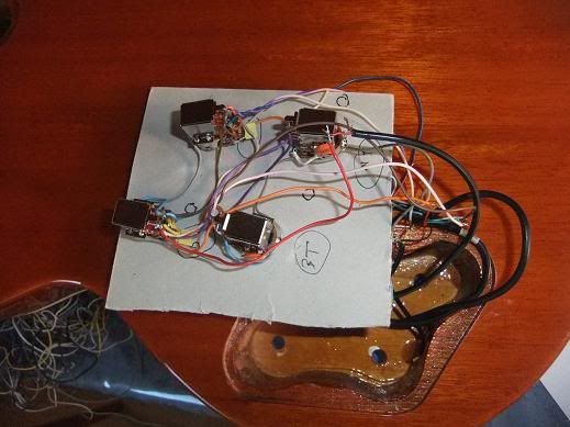 It did take a few hours to do this, not all "professionals" are going to be as patient perhaps, but there is no substitute for doing things this way to be sure... So, you can see I wired it up exactly as in john's diagram of the original design, with the pots mounted to a piece of cardboard suitably labeled so as not to get confused. This thing is going to be near impossible doing it inside the cavity... I then took leads from all the pickup lead connections out and tacked the pickup wires as I assumed would be correct and two false connections and I got it right...then, trimmed and hard wired before taking the cardboard out and fitting the pots in the guitar. Soooo.... This means that not only is the design verified, so is john's invaluably clear drawing...so we can rule that out.The only variation is that I didn't flip the magnet...I may do this and may have to swap some wires if I do, the guitar is crazy quiet, even in single coil mode, but it would seem that the two splits are not HB and the inside coils...a great sound though...but not a problem with the design and it can clearly work without doing that magnet flip thing. There are quite a few combinations from those 4 conductor pickups, join the wrong two together (which some of the switches do to make the functions work) and you could short the pickup or halve it or phase it or anything...so you have to be able to work out which is which. My pickups were new, so I had a clue, the green and whites on each were joined so I knew one would be the end of one coil and the start of another. I hope you have success sooner than later, it will work so don't panic and john knows his stuff so I will leave him to the trouble shooting...and you have made a good choice, all the sounds are great on my guitar and the layout intuitive and very stealthy. I can understand why some would think this job should be left to a "professional" but often these things are just so time consuming that you can't pay people to do it, especially the super custom stuff...some experience is needed to solder well, but most of the difficulty people have is taking short cuts, working in the cavity and not testing and troubleshooting things systematically good luck, and look out for my guitar when it gets closer to completion, the wiring was so good, I've upgraded the specs and have to wait a bit longer for the new parts... |
|
|
|
Post by JohnH on Jun 13, 2010 20:27:04 GMT -5
Hi Raz - I just thought Id call in on this thread. Any progress with testing/fixing your guitar? The next step is with a multimeter and Ill be around here someplace when you are ready.
John
|
|
Raz59
Meter Reader 1st Class
Posts: 71
Likes: 0
|
Post by Raz59 on Jun 16, 2010 16:32:37 GMT -5
Yes John, sorry for the long absence. I finally got a hold of a multimeter. There's one peculiar thing when measuring my bridge humbucker...I managed to read 9KΩ one time...then I read 7KΩ...I suppose this was because of the volume pot being on 9 or something.
But without further ado. The resistance of my cable is about 3Ω, so I guess it can be dismissed. All of the readings were done by connecting my cable to the guitar, the multimeter tips were placed on the other end of the cable. All pots on 10:
1. (neck selected, all pp's down)
8,45KΩ
2. (neck selected, S3 pulled)
4,25 KΩ
3. (bridge selected, all pp's down)
7,00 KΩ
4. (bridge selected, S4 pulled)
3,55 KΩ
5. (S3 and S4 pulled, bridge is still selected)
7,00 KΩ
6. (Both pups selected, all pp's down)
3,85KΩ
7. (S1 pulled, other pp's down)
15,46KΩ
8. (S1, S3 and S4 pulled)
4,25KΩ
The phase inverter (S2) theoretically doesn't change any values, so I didn't bother writting those values down. And that's it!
|
|
|
|
Post by JohnH on Jun 16, 2010 22:25:33 GMT -5
OK thanks for those. I will consider and get back to you with any conclusions, probably tomorrow. You are right that the phase switch should make no difference, but since we are looking for some fault or discerepancy, it would be worth confirming that. No need to post all the values, but just be sure that in various settings, the phase switch does indeed, make no diference to resistance (you might get a jump as you pull the switch, but it should settle back to the same value).
cheers
John
|
|
Raz59
Meter Reader 1st Class
Posts: 71
Likes: 0
|
Post by Raz59 on Jun 17, 2010 15:02:31 GMT -5
Right, then for the sake of finding faults, I re-checked all settings. The phase switch doesn't alter the resistance values (there is the jump you mentioned, but I consider that normal).
But one thing that I just found out. Remember the resistance value that is measured when you connect both pickups in series and you split them both by pulling S3 and S4?
8. (S1, S3 and S4 pulled)
4,25KΩ
I get the SAME value (4,25KΩ) if I push down S4 (bridge series/parallel switch). I guess I can affirm that S3 overrides S4. So here's one problem: S3 and S4 are not interacting like they should.
The same happens when both pickups are connected in parallel (S1 is down) - S3 overrides S4.
|
|


