crumble
Rookie Solder Flinger

Posts: 11 
Likes: 0
|
Post by crumble on Jul 30, 2010 11:56:34 GMT -5
Hello everyone.
I'm building a guitar and going to do a kind of crazy wiring scheme "hopefully"... What I want is:
2 humbuckers, 2 volume knobs, 2 tone knobs, a 3pdt on/on mini switch for master series/parallel + extra pole to send both signals to different volume knobs (one volume knob for series, other for parallel), and a dedicated tone knob for each volume knob. Then a dp3t on/on/on mini switch to choose which humbucker (neck/inner coils split together/bridge), and one last dtdp on/on mini switch as a killswitch (signal to amp/signal to ground)..
whew, ya, I have searched the internet high and low to find a diagram that does this, but I couldn't find anything.. I dont know what to do..
If anyone knows of a diagram that does this or could help walk me through drawing my own, i would be sooooo grateful.
|
|
|
|
Post by JohnH on Jul 30, 2010 16:24:11 GMT -5
Hi crumble and welcome to GN2.
I'm pretty sure I can answer the first part of your question: that there is unlikely to be an existing diagram that does this!
How's your electronics? ie, when you take a look through the schematics on this site, can you follow/understand them?
I think there's two next steps
1. is to try to break the problem down, splitting off the easy bits - eg, the volume and tone controls can each be a standard block wired conventionally. The kill switch is easy - right at the end of the circuit just before he jack, it shorts the output to ground - that is the best way to do that.
2. is to think further on exactly what should happen in each switch position. eg, when you select series or parallel, what should happen when you also select just one pickup?
I can see some complication, in that things you describe early in the circuit, like master series/parallel before the volume controls, are affected by other functions later in the circuit, such as the neck/both split/bridge control.
Are you sure you want separate series and parallel V and T, instead of separate neck and bridge V and T?
When you describe master series/parallel, are you refering to combinations of the bridge pickup in series or parallel with the neck pickup, or do you mean series/parallel of the coils within each separate pickup?
cheers
John
|
|
crumble
Rookie Solder Flinger
Posts: 11
Likes: 0
|
Post by crumble on Jul 30, 2010 19:37:58 GMT -5
Ya, i pretty much want to be able to set one volume for when in series mode, and the other for when in parallel mode. Series and parallel have different output levels (series hotter), so I want to be able to set the volume for both beforehand then I can switch to anyy pickup configuration and the volume level wont be all over the place..
So the way I want the pickup selector and the master series parallel switch to be is, if I switch to series mode, and series volume is active, any pickup position I select (neck hb/inner coils/bridge hb) are all series, and vise versa for parallel mode.
|
|
|
|
Post by JohnH on Jul 30, 2010 20:46:51 GMT -5
OK, so, lets say you are in series mode, then your three settings are:
neck both coils
neck inner and bridge inner
bridge both coils
And so in each case, two coils are active, in series, then flick the S/P toggle and the same pairs are in parallel?
If so - it makes sense. just gotta think how.......
J
|
|
|
|
Post by newey on Jul 30, 2010 21:45:26 GMT -5
crumble- John's right, there's no schematic in the vaults to do exactly this scheme of yours. I looked. The closest I could come was this, from last year by ekso: guitarnuts2.proboards.com/index.cgi?board=schem&action=display&thread=4126Granted, this may be "close" only in the sense that it's 2 HBs with series/parallel and a killswitch. And, as noted in the thread, there's some issues with the diagram, and ekso never checked back in to discuss these further. So I'm not suggesting this as an answer, only as a starting point. At the very least, you can lift the module for the killswitch from it!  Your idea is interesting from a playability standpoint, I like the idea of separate series and parallel controls. I'll ponder this awhile, and then undoubtedly get beaten to the punch by one of JohnH's classically elegant solutions.  |
|
|
|
Post by JohnH on Jul 30, 2010 22:23:52 GMT -5
.... get beaten to the punch by one of JohnH's classically elegant solutions. I hate it when that happens.  This is a schematic sketch, No, Bi etc, refer to Neck outer, Bridge inner coils etc also in brackets (S) or (N) to refer to different magnetic poles. I reckon you need a 4 pole switch for series/parallel (S2). to properly select and cut out the volume and tone groups. Also, the main coil selector (S1) has a four pole on/on/on. of which three are used, to fully cut out the unused coils without hanging from hot. Could at a pinch, avoid pole S1C and use a dpdt on/on/on, at risk of more buzz, unless you have covered pickups. As shown on the sketch, it is selecting bridge, in series mode. As you move S1 to the centre, pole S1A changes, leaving S1B and S1C as they are, to do the inner coil combo. Then move fully down and the other S1 poles change to select both neck coils. Does that make any sense? Can you go from there to a wiring diagram? Also, if you wish, one more simple switch could give you single coil sounds too. cheers John |
|
|
|
Post by ashcatlt on Jul 30, 2010 22:54:14 GMT -5
Boy John, you don't waste any time!
That's pretty inventive, and I'm going to +1 it.
S3 could just as easily be SPST and doesn't have to be momentary (wasn't specified in the OP).
|
|
crumble
Rookie Solder Flinger
Posts: 11
Likes: 0
|
Post by crumble on Jul 31, 2010 11:35:31 GMT -5
Wow, thanks John! I take it this is the solution?! I'm not used to schematics for wiring, used to diagrams i guess. I'm looking at your sketch and reading through your paragraphs below it, trying to decypher it, this is tough. Is this right? How the switches will need to be to make it work? I haven't started trying to connect the dots yet.. 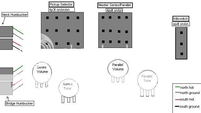 This is how knob setup on face of guitar will look.. 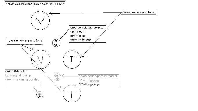 Now I just have to try to convert your language "sketch" into my language "connecting dots", heh. |
|
|
|
Post by ashcatlt on Jul 31, 2010 13:12:36 GMT -5
The pickup selector and S/P switch should have the same pinout (exactly like the pickup selector you've shown above). See here (second row, first column) for the specifics of how the On-On-On Pickup Selector will work. You're going to skip one of the poles, use two like poles and one of the others. As John drew it, ,the kill switch (SPDT) should have one more lug, but as I said an SPST (as you've drawn) will work fine. You're not using that extra lug anyway. If you go for momentary, make sure it's normally open. |
|
crumble
Rookie Solder Flinger
Posts: 11
Likes: 0
|
Post by crumble on Jul 31, 2010 13:24:52 GMT -5
Thanks for the catch, the image should be right now.
Ya, i'de perfer a double throw switch for the killswitch so i can set it to kill when i put guitar down so i dont have to mess with the volume knobs.
Having a hell of a time decyphering this sketch, i'm such a newbie..
|
|
|
|
Post by ashcatlt on Jul 31, 2010 13:29:22 GMT -5
You don't need double throw for that, you just need latching.
|
|
crumble
Rookie Solder Flinger
Posts: 11
Likes: 0
|
Post by crumble on Jul 31, 2010 15:24:52 GMT -5
After staring at that sketch for a few hours, I can see exactly how it would work, and it looks perfect. But I am having trouble translating it to a diagram for the actual wiring..
|
|
crumble
Rookie Solder Flinger
Posts: 11
Likes: 0
|
Post by crumble on Jul 31, 2010 16:04:01 GMT -5
Hmm, would this be correct for what i'm trying to do? except need to change the pickup select pot with 4p3t? "thanks to A440hz on talkbass for the diagram"  |
|
|
|
Post by JohnH on Jul 31, 2010 16:27:55 GMT -5
After staring at that sketch for a few hours, I can see exactly how it would work, and it looks perfect. But I am having trouble translating it to a diagram for the actual wiring.. Hi crumble! if you have taken the time to stare at my sketch and have followed how it works, then I am highly delighted and im very happy to help further. These 'schematic' diagrams, although they need a further mental leap to figure out exactly where the real wires go, are the best way to design a circuit. Once the flow paths are figured out, then it gets translated into a wiring diagram for construction. So onto your last diagram. Ill check it. Different style to your previous. Did you do it yourself, or was it from another source? It has only the two pole coil selector, which per my first post, can work with the omision of pole S1C, but you will see that both hot wires are alway connected. The disused one can pick up a very small amount of noise. This often does not matter too much. But in this case, your scheme has the potential to be exceptionally well controlled and quiet with regard to hum and noise, so its worth getting it just right. Ill be back when Ive studied the diagram some more. John |
|
crumble
Rookie Solder Flinger
Posts: 11
Likes: 0
|
Post by crumble on Jul 31, 2010 16:37:48 GMT -5
I was asking about this scheme on another forum and some awesome fellow "A440hz" drew that up.
The diagram looks right except i'm gonna trust you on the 4p3t instead of dp3t for the pickup selector.
Anxious to hear if that diagram is right (other than the dp3t instead of 4p3t).
|
|
|
|
Post by JohnH on Jul 31, 2010 16:52:53 GMT -5
OK, thats fine! I saw your thread on ProjectGuitar, but they didnt seem to have got there yet. So which forum was it?
The design is essentially the same as I was sketching and will work fine. If you do the enhancemnt with the four pole on/on/on, it will appear on the diagram as two similar poles next to the current two, which in the middle position connect one up, one down. To match the diagram, the third pole that you need to use will be the one that connects down in the middle position.
On a general note, theres no problem posting questions in several forums but when you are asking for help that requires significant work, it would be better to declare where these threads are, to avoid doubling up effort. My sketch was quick to do, but that nice wiring diagram would have taken quite some time and it wouldnt be fair to ask someone else to repeat it elsewhere.
cheers
John
|
|
crumble
Rookie Solder Flinger
Posts: 11
Likes: 0
|
Post by crumble on Jul 31, 2010 18:09:50 GMT -5
Ya, I tried to post the diagram as soon as I saw it so no doubles were made. Diagram is from talkbass forums, on pickups and electronics subforum.
I appreciate all the help from you and everyone else here. Even though these schematics were way over my head yesterday, i'm starting to understand how it all works after just studying your words/sketches.
Last thing that is confusing me about the 4p3t switch is, you said I need the extra pole that connects down in middle position.. you said the inactive pickup will be grounded with this extra pole, but, where am I taking the wire from to ground it with that pole? Is it just to ground the outer coils when i'm in middle position using the inner coils? Or will it ground the inactive pickup in every setting?
|
|
|
|
Post by JohnH on Jul 31, 2010 18:53:44 GMT -5
What i mean is, to add the extra pole S1C like this. It doesnt ground anything, it just selects the hot from bridge or neck coils.  Ive drawn the extra poles up the top for clarity , but obviously they are really part of the same switch, as indicated by the arrow |
|
crumble
Rookie Solder Flinger
Posts: 11
Likes: 0
|
Post by crumble on Jul 31, 2010 19:17:15 GMT -5
Ohh i see, i'm gonna add that in for sure. Man, this is gonna be a lot of wires inside the control cavity.. but totally worth it.
Thanks again for all your help, I can even post up sound samples when I complete the guitar if you curious to how it'll sound.
|
|
|
|
Post by JohnH on Aug 1, 2010 2:02:23 GMT -5
Yes well good luck
And I saw what A440hz posted. He seems like a pleasant and very knowledgable fellow
He should be here!
On your kill switch, what will you use it for? Is it to quiet the guitar between sets, or is to make stacatto effects? Given both ideas, you can get a single pole on-off-momentary toggle, with three lugs. In the centre (off), nothing is connected, and the guitar is on. Flick it one way and it could short out the guiar but return to centre for those effects. Flicjk th eother and it stays flicked, to shunt the guitar off while you take a break.
When you get to do your wiring, it wont be too hard now that its drawn out. Its often a good idea to mount the parts on a cardboard template out of the guitar, and make as much of the harness as possible first, then put it in the eguitar and just connect the pickups and output, plus bridge ground wire.
John
|
|
crumble
Rookie Solder Flinger
Posts: 11
Likes: 0
|
Post by crumble on Aug 1, 2010 10:24:52 GMT -5
Ya, I was just looking for the killswitch to kill the signal in the middle of songs when the other guitar and I jump back and forth between solos and stuff. And so I can kill the guitar when I go to set it down between sets, etc.
The momentary switch, i've never messed with one, how exactly do those work differently?
I'm just worried about popping sounds with the killswitch. If I am driving my signal through a amp that is driven hard and turned up pretty loud, will i get loud pops when i hit the killswitch or when I jump back to the signal?
Also, know of a good place to buy 4p3t switches? I found an explosion proof 4p3t switch for $250...
|
|
crumble
Rookie Solder Flinger
Posts: 11
Likes: 0
|
Post by crumble on Aug 1, 2010 10:53:32 GMT -5
|
|
|
|
Post by JohnH on Aug 1, 2010 19:16:10 GMT -5
nice try, but a combo of on/on/on and on/off/on sounds mysterious and not quite right. Im not familar with the very best places to buy switches, unless you are down-under, but here is a range of products that look suitable, from mouser. all by the same C+K manufacturerer. Id like to ask others (sumgai, newey?) to have a look at these and the prices, and advise whether there is a better product or better price. 4pdt on/on/on for switch S1 au.mouser.com/ProductDetail/CK-Components/7411P3YZQE/?qs=sGAEpiMZZMvudeGI7i40XIOzddihj%2fvziHd7HzbdbKs%3d4pdt on/on (noted here as on/none/on ie a 2 position switch, for switch S2 au.mouser.com/ProductDetail/CK-Components/7401SPHCQE/?qs=sGAEpiMZZMvudeGI7i40XDrGNm15cOKCQ3rC3uUCnxg%3dSimple two position single pole switch, for kill switch spdt on/on au.mouser.com/ProductDetail/CK-Components/7101SYZQE/?qs=sGAEpiMZZMvudeGI7i40XAeeinsqjztB93Horawxbf4%3dor, Three position switch, for kill switch on/off/momentary au.mouser.com/ProductDetail/CK-Components/7108SCWZQE/?qs=sGAEpiMZZMvudeGI7i40XN8uIGLn3j7n%252b%2fNpNA3%252b4H8%3dOn your question of popping noise, id make one more change to your diagram, to match my sketch: let the output go straight to the jack, and have the kill switch just short it to ground. That way, the output is never disconnected during switching and pops are unlikely to occur. John |
|
|
|
Post by newey on Aug 1, 2010 19:48:06 GMT -5
I'll have to take a look, I've never used a 4P switch in anything, so never had a reason to look for one. However, when some of these relative rarities are found, we should be posting them in the Reference section, Specific OEM Parts Links. Hopefully, we'll get a good list of these hard-to-find ones posted, and so not have to re-search all the time. |
|
|
|
Post by JohnH on Aug 1, 2010 19:59:15 GMT -5
thanks newey
Further on the thought of having a ‘momentary’ switch for a kill switch:
Sometimes, when I’m doing a heavy rhythm on an LP, I use the bridge pickup and turn the neck to zero volume. Then while the last chord fades away, I can use the toggle selector as a kill switch to make a pulsing effect. But to do this, it would be easier and more expressive if the switch returned to the centre, so I only had to push it one way and have it spring back, instead of push it, then pull it. Of course, a standard toggle does not do that. So, if I was building in a purpose-designed kill switch, it would be a ‘momentary- off-on’ toggle. Pushing it down, it cuts the signal but springs back to the centre, pulling it up, it stays up, for longer breaks. Three lugs, the centre lug goes to hot, the outer lugs both go to ground.
John
|
|


