|
|
Post by JohnH on Oct 22, 2016 14:41:45 GMT -5
thanks reTrEaD for your inputs above, all fine.
|
|
leon1
Rookie Solder Flinger

Posts: 22 
Likes: 0
|
Post by leon1 on Oct 27, 2016 14:24:39 GMT -5
Hey Guys,
I finished the soldering. Sounds are coming out of the guitar, but I have got a serious grouding issue(very hard brum). It seems extra strange because I have Lace Sensor pickups.
Tomorrow I will continu trouble shouting (I also shielded the guitar this time).
Léon
|
|
|
|
Post by JohnH on Oct 27, 2016 15:39:11 GMT -5
Hey Guys, I finished the soldering. Sounds are coming out of the guitar, but I have got a serious grouding issue(very hard brum). It seems extra strange because I have Lace Sensor pickups. Tomorrow I will continu trouble shouting (I also shielded the guitar this time). Léon Sorry to hear that, but we will figure it out. Do you have a multimeter? A resistance reading across the guitar cord may reveal some info, if you don't figure it out just by looking. At full volume, the resistance should match (or be v slightly less) than the pickups based on whatever setting you have (eg, if your pickups ae 6k, you get 1/2x6k for two I parallel, 2x 6k for two on series, or 6k for a single), . Turning down, the resistance should rise to about 1/4 of the volume pot value (about 130k for a 500k pot), at about 6 or 7 on the knob (log pot), then fall to zero at zero volume. If at full volume you read about 500k, then the volume pot has a ground but the pickups may be missing it. If you are above 500k, then there is no ground connection. If you read zero or very low readings, then there is a short circuit to ground (but these are normally very quiet, no hum) |
|
leon1
Rookie Solder Flinger
Posts: 22
Likes: 0
|
Post by leon1 on Oct 27, 2016 16:17:24 GMT -5
Hi Mark, Yes, I do have a multimeter. Where must I connect the + and - of the multimeter regarding reading the resistance of the volume potentiometer? This message is with one eye closed  . I'm gonna catch some sleep. |
|
|
|
Post by JohnH on Oct 27, 2016 16:20:17 GMT -5
btw, I'm John
just plug a guitar cord into the guitar and read between the barrel and the tip of the plug at the other end of the cord.
|
|
leon1
Rookie Solder Flinger
Posts: 22
Likes: 0
|
Post by leon1 on Oct 27, 2016 16:23:10 GMT -5
OK, I will. Sorry for mistaken your name. I really have to get some sleep  |
|
leon1
Rookie Solder Flinger
Posts: 22
Likes: 0
|
Post by leon1 on Oct 28, 2016 6:54:12 GMT -5
John, I did the readings. A lot of values keep jumping up and down, (example: 11,05 / 11,07 / 11,08 /11,11). If have done multimeter measuring in the past, but this kind of jumping I have never seen before. I used this diagram:  a) Turning down the volume to zero I measure zero resistance. b) Turning volume max open: 5,6 K b) Turning volume to 20% open: 30 K c) Turning volume to 65% open: 70 K e) Turning volume to 90% open: 16 K f) Turning volume to 97 open: 6,1 K ======================================= Position 5 (Humbucker): SW 2: up: 5,9 K SW 3: up: 5,90 K to 5,91 K (jumping up and down, like clock work) SW 3: down: 11,46 K to 11,52 K (jumping up and down) ========== Position 4 SW 1: up SW 2: up 11,15 K to 11,21 K (jumping up and down) SW 3: down SW 1: down SW 2: up 2,84 K (steady) SW 3: down SW 1: down SW 2: up 2,88 K (steady) SW 3: up SW 1: up SW 2: up 11,32 K to 11,37 (jumping up and down) SW 3: up ============== Position 3: SW 1: up SW 2: up 5,60 K to 5,61 K (jumping up and down) SW 3: up SW 1: down SW 2: up 0 k SW 3: up SW 1: up SW 2: down 11,31 K to 11,37 K (jumping up and down) SW 3: up SW 1: up SW 2: down 16,68 K to 11,81 K (jumping up and down) SW 3: down ============ Position 2: SW 1: up SW 2: up 5,60 K to 5,61 K (jumping up and down) SW 3: up SW 1: down SW 2: up 0 K SW 3: up SW 1: up SW 2: down 11,05 K to 11,11 K (jumping up and down) SW 3: up SW 1: up SW 2: down 11,03 K to 11,09 K (jumping up and down) SW 3: down ============== Position 1: SW 1: up SW 2: up 0 K SW 3: up SW 1: down SW 2: up 0 K SW 3: up SW 1: up SW 2: down 5,59 K to 5,60 K (jumping up and down) SW 3: up SW 1: up SW 2: down 5,59 K to 5,60 K (jumping up and down) SW 3:down |
|
|
|
Post by JohnH on Oct 29, 2016 1:52:25 GMT -5
Its a bit hard to tell from the list
The volume pot seems ok, and 70k is the right maximum when the treble bleed resistor 150k is there.
Position 1 and 5 seem like they may be OK, do they work?
The other readings are mostly good, but there should not be the zero readings.
Operating the phase switch SW2 should not make any difference
the jumping can be just the meter tip moving during the test, or it may mean a connection is intermittent.
|
|
leon1
Rookie Solder Flinger
Posts: 22
Likes: 0
|
Post by leon1 on Oct 29, 2016 2:38:02 GMT -5
John, I did post the wrong schematic in the last post. I build it corresponding this schematic:  It's definitely not the meter tip moving. Could it be that i fried one or more capacitors? Because the current (aka ohm's ) goes up and down? I will do another visual inspection. After that I want to desolder the capacitors, to see if it makes a difference. |
|
grooveiron
Rookie Solder Flinger
Posts: 7
Likes: 0
|
Post by grooveiron on Feb 5, 2017 17:01:43 GMT -5
I finally got around to installing this terrific wiring in my PRS SE EG. Everything works as expected, and I love the sounds, but the series fade does nothing except act as another potentiometer for the 47 capacitor in series mode. Looking at the diagram, it seems that this is what it would do, so I am confused about how the series fader is actually supposed to work. If you can enlighten me, I would be so grateful, as I miss my middle pick up on its own!
|
|
|
|
Post by JohnH on Feb 5, 2017 19:24:32 GMT -5
I finally got around to installing this terrific wiring in my PRS SE EG. Everything works as expected, and I love the sounds, but the series fade does nothing except act as another potentiometer for the 47 capacitor in series mode. Looking at the diagram, it seems that this is what it would do, so I am confused about how the series fader is actually supposed to work. If you can enlighten me, I would be so grateful, as I miss my middle pick up on its own! Thanks for uour interest. If you select N and M in position 2, then reduce the fade control, it should move to M only. No cap is involved in that case so you end up with pure M |
|
grooveiron
Rookie Solder Flinger
Posts: 7
Likes: 0
|
Post by grooveiron on Feb 5, 2017 20:34:07 GMT -5
Hello John, thanks for you reply. I know from your descriptions what should happen, but in my build, turning down the series fader pot simply acts like turning up the top end of the tone pot. Looking at the wiring diagram leaves me wondering how the volume control part of the series fader would work - nothing is shunted to ground in the way that the series fader is connected. Do I have the wrong wiring diagram? all the best to you, John Attachments:
|
|
grooveiron
Rookie Solder Flinger
Posts: 7
Likes: 0
|
Post by grooveiron on Feb 5, 2017 20:59:47 GMT -5
I've just noticed something else odd - when in positions 1 or 5, irrespective of S or P mode, the top end of the tone control (and the series fader) fatten up the sound of N or B. It's not an unpleasant effect, but I'd rather have the designed functionality.
Hmmm, I will recheck all connections in the morning…
|
|
|
|
Post by JohnH on Feb 5, 2017 21:09:23 GMT -5
You have a later anmended version. Id suggest to move the blue wire on the fader to the other end of the 47nF cap. Also try after that, disconnecting one end of the 47nF. Or see page 1.
|
|
grooveiron
Rookie Solder Flinger
Posts: 7
Likes: 0
|
Post by grooveiron on Feb 6, 2017 8:29:45 GMT -5
Id suggest to move the blue wire on the fader to the other end of the 47nF cap. Eureka! That fixed it, thanks so much! The "fattening" effect I described is still there, which is nice, but it's only really noticeable when vol < max. I love how this works! Fantastic design, John! |
|
crillev1
Apprentice Shielder

Posts: 34
Likes: 3
|
Post by crillev1 on Jul 12, 2017 1:59:21 GMT -5
Hi John,
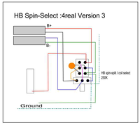
Would it be possible to exchange the fader control and the bridge coil cut switch with the "HB Spin-select: 4Real version 3",
found in the "HSS, with variable coil cut and bridge-on" thread?
|
|
|
|
Post by JohnH on Jul 12, 2017 3:37:34 GMT -5
Hi John, Would it be possible to exchange the fader control and the bridge coil cut switch with the "HB Spin-select: 4Real version 3", found in the " HSS, with variable coil cut and bridge-on" thread? Sure. I suggest basing it on the Revision B diagram on page 5. Just delete the two wires that are shown going to the fader pot and move the two wires that are shown on the coil-cut switch to those same two pot lugs. Welcome to GN2 |
|
crillev1
Apprentice Shielder
Posts: 34
Likes: 3
|
Post by crillev1 on Jul 12, 2017 8:31:55 GMT -5
Hi again John, Thanks for the fast reply. There are two Rev B. drawings on page 5. I'd liked to work with the Autosplit version if possible. Actually I see three wires on the bridge coil cut switch. One purple, one green and one red. Which two wires do you mean? If I make this mod, will I still retain all the other possibilities (except series Fader)? While I'm at it, could the "Half out of Phase" circuit by 4Real be implemented somehow as an addition. it's at guitarnuts2.proboards.com/thread/5176/half-out-phaseI realize that it needs an extra pot.  |
|
crillev1
Apprentice Shielder
Posts: 34
Likes: 3
|
Post by crillev1 on Jul 12, 2017 10:50:40 GMT -5
Does your suggestion mean that you omit the HB Spin-select switch and just use the 250K pot?
Sorry, for the Half-out-of-Phase circuit I meant of course an extra switch, not an extra pot.
BTW, I do have an Fender S1 switch lying around if that makes things simpler.
|
|
crillev1
Apprentice Shielder
Posts: 34
Likes: 3
|
Post by crillev1 on Jul 12, 2017 12:33:41 GMT -5
JohnH, as a sideshow to the SP HSS diagram, I made some changes to your Strat SP SSS diagram for my SSS Strat. I liked the idea of a middle PU blend pot that is a part of the Dial-a-Duck diagram, since I really want have a lot of quack in pos. 2 and 4. guitarnuts2.proboards.com/thread/3825/dial-duckVince from the UK mentioned in the Dial-a-Duck thread that putting a 0.1uF cap on the middle PU in series with the signal, when the PU is out of phase is supposed to maximize the "Quack". If you agree that this is a good way to get lots of quack, I suppose I could solder a 0.1uF cap to the signal jumper (black) on the OoP switch that sits on the Tone pot. BTW, the Super-switch numbering on my diagram is opposite to your numbering.  |
|
|
|
Post by JohnH on Jul 12, 2017 15:24:50 GMT -5
In my last post, I meant the first drawing Rev B on page 5, not the auto split one. So there's just the two wires to pot and to switch shown. I think the autoplit version is probably not suitable for the split a split idea. But as suggested, it should work with all other functions intact.
Adding more stuff to this design is a bad idea IMO, it already has 85 basic sounds and a number of variations. I don't think there is any clear definition of 'quack' or how to maximise it, but I believe that whatever it is, there will be heaps of it in this design.
If you really need to add more, it looks to me that the half out of phase and related versions imply putting a cap in-line with one pickup. So you could take one of the N or M pickups and wire it in series with a cap before it connects to anything else. Then short that cap out with an extra switch to negate it.
|
|
crillev1
Apprentice Shielder
Posts: 34
Likes: 3
|
Post by crillev1 on Jul 13, 2017 0:03:20 GMT -5
OK, I see what you mean now. Here's my interpretation of your suggestion.  But....., isn't this more like a Blender? if I look at the HB Spin-Select diagram, I can choose which coil I want to use (inner or outer). It seems that this functionality is missing here, or ....? Quote: "In the normal position the guitar is pretty much as it was before, you have the split to the sweeter inner coil on zero, turn towards ten to get a full HB which comes in around 8 or 9 on the dial with the 250K pot.
In the pulled up position, you get the split to the brighter outer bridge most coil, as you turn towards ten you get an interesting 'swell' in tone and at the far end you get a different HB sound, something more akin to a P-90 in a way.
"
 |
|
|
|
Post by JohnH on Jul 13, 2017 2:51:10 GMT -5
What i suggested was just a simple variable split from humbucker to one coil. I think you drew it right. It preserves humcancelling where possible.
You could do 4reals one instead, and get more variations of similar tones with half of them being non-humcancelling when there are others that could be. Serious risk of option fatigue!
|
|
bajaking
Apprentice Shielder
Posts: 29
Likes: 0
|
Post by bajaking on May 17, 2018 15:23:43 GMT -5
Hi John, Hello to everybody else, Newby here :-) I would like to implement this great scheme on my new custom HSS Strat build. I would prefer that when all the push/pulls are in the down position that the guitar was: Sw1: In Series Sw2: In Phase Sw3: No coil tap Which version of the diagram should I use please? I will be using a Schaller Megaswitch M  schaller.info/en/megaswitches-preamp-pickups/420/megaswitches?number=15310006&c=19 schaller.info/en/megaswitches-preamp-pickups/420/megaswitches?number=15310006&c=19Thanks in advance Steve |
|
|
|
Post by JohnH on May 17, 2018 22:23:49 GMT -5
Hi bajaking, thanks for your interest in this scheme and welcome to GN2. I think the best basic version is Rev B from August 23 2015. But if you want the pushed-in mode to be all series combos of pickups, reverse the wires on SW1. ie, keep the middle connections as is, but swap top to bottom the other wires to this switch as shown on diagram. Also, for pushed in = no coil cut, move the SW3 top left wire to bottom left. Wire colours shown are based on Seymour Duncan. The other thing to check is phase and magnet polarity on your pickups. Coils of opposite magnetism are coloured differently on the diagram (doesn't actually matter which is north or south, its the relativity that is key) Good luck and let us know how you get on. Here is that diagram:  |
|
bajaking
Apprentice Shielder
Posts: 29
Likes: 0
|
Post by bajaking on May 18, 2018 4:10:09 GMT -5
Thanks John for your swift reponse. I'm using Iron Gear pickups: Neck (Pig Iron Overwound) is Black-ground/white + Middle (Texas Loco RW-RP) is Black-ground/yellow + Bridge (Rolling Mills Overwound) see diagram  I can translate the wiring to match the diagram but I have found the following: The neck pickup is attracted to the middle pickup The neck pickup is attracted to slug side of the humbucker The middle pickup is attracted to the screw side of the humbucker (nearest the bridge) If I understand correctly this is different to your diagram. If want to keep the pickups in their relative positions, how would I proceed to correct this? Thanks in advance |
|
|
|
Post by JohnH on May 18, 2018 7:48:46 GMT -5
ok no prob, but let me look at it in the morning after a coffee!
|
|
bajaking
Apprentice Shielder
Posts: 29
Likes: 0
|
Post by bajaking on May 18, 2018 7:50:55 GMT -5
Great, Thanks  |
|
bajaking
Apprentice Shielder
Posts: 29
Likes: 0
|
Post by bajaking on May 18, 2018 11:10:20 GMT -5
Also John so that I can match up the mega switch M, does the super switch in this diagram match your one... Thanks  |
|
|
|
Post by JohnH on May 18, 2018 16:37:03 GMT -5
OK so for your pickups, and relating them to the diagram:
For physical positioning, I believe Neck and Screw coil are in blue positions, Middle and Slug are in pink positions.
The idea is that all in-phase combos where you split the bridge, will involve a pink and a blue coil and therefore be hum-cancelling. If you also pull the phase switch, you get two of the same colour, out of phase, which is also hum-cancelling. Neat eh? (I was pleased with that!)
This will mean that the BN and BM combos will also be 'inner' and 'outer' coils, for in-phase settings - this makes them sound nicely different.
Now to wire colours:
I think it will be this:
Diagram - Irongear Hb
red/white - red/black
green - green
black - white
This assumes the singles have black where the diagram has black.
Im posting this, but I want to check it again later!
The switch is doing my head in, it seems to have 12345 positions flipped and inverted on each side. Can anyone advise on that?
|
|


 . I'm gonna catch some sleep.


