mortis1369
Rookie Solder Flinger

Posts: 22
Likes: 0
|
Post by mortis1369 on Jun 20, 2011 16:21:04 GMT -5
no no no no no... I have the new switch, and the old one. The new one, when hooked up produced no sound whatsoever. So I went back to the old switch which is a US style 5-way regular switch. When I hooked this one up, I got sound, but the hum came back. I know it shouldn't be happening, as they are called humbucker's for a reason, and that is why I am a little upset. But I do not see many options as to what I can do about it. I can try to buy a new switch, a genuine fender switch (prolly US style switch), or I can bypass altogether and have no switch (I dont want this), Or, I can change to a basic 3 way (leaning toward this option). I think this is about it for my options. But either way, I will still need to buy another DMM.
|
|
|
|
Post by sbgodofmetal on Jun 21, 2011 20:27:23 GMT -5
Honestly get the 3way there'd be no redundant or repetative selections and you'll keep a stock appearance. Theres problems with what your wanting it to do. 1st off no matter how many lugs your standard 5way has your going to have at least 2 positions 'EXACTLY' the same, your better off using a tele 3way or just fork out the extra for a mega or superswitch, but with only 3 conductor humbuckers your still going to exhibit the same problems your only logical option is to buy the 3way switch. JMHO.
HTH
SBG.
|
|
|
|
Post by sbgodofmetal on Jun 21, 2011 20:47:28 GMT -5
Or you could use the 5way as a varitone switch convert the middle pot to a dual concentric and slap your flavor of rotary switch in the tone 2 position on the pickguard. My personal recomendations are on the switch, left bridge pos, .001uf, middle pos, .022uf, neck pos, .039uf. on its right, bridge pos, .047uf, middle pos, .050uf, neck pos, .061uf(wire a .039uf and a .022uf to the same lug for this one) then run the left common to the top half of the dc pot and the right to its bottom half.
|
|
|
|
Post by sbgodofmetal on Jun 21, 2011 20:56:01 GMT -5
As for the rotary i'd recommend using an SP3T 3way rotary and setup like a tele,
pos1, bridge.
pos2, neck and bridge,
pos3, neck.
but thats what i'd do. Now if you had 4conductor hbs you could incorperate coil splitting and/or tapping.
lts simplistic, discrete, and effective plus the added tones will add some interesting sounds, its a win-win for most.
hth
sbg.
|
|
|
|
Post by sbgodofmetal on Jun 21, 2011 21:21:35 GMT -5
This is all i've got diagram wise, for the bass tones just add the caps to the 3 empty lugs. 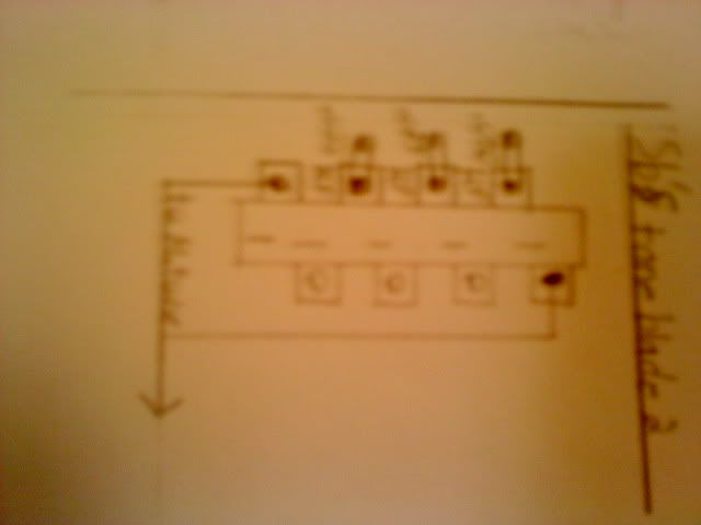 but for using that 7lugger you'll omit the right side altogether and then switch to, bridge pos, .001uf, middle pos, .039uf, neck pos, .050uf, and just use a regular tone pot. |
|
|
|
Post by ashcatlt on Jun 21, 2011 21:47:00 GMT -5
To "set it up like a tele" requires two poles on a true three position switch.
|
|
mortis1369
Rookie Solder Flinger
Posts: 22
Likes: 0
|
Post by mortis1369 on Jun 22, 2011 18:10:49 GMT -5
To "set it up like a tele" requires two poles on a true three position switch. What do you mean by this? I am still a little ignorant on these matters, but what I was suggesting was that I buy a 3 way switch and just use that. Cant be too difficult to wire up right? |
|
|
|
Post by ashcatlt on Jun 22, 2011 18:43:18 GMT -5
A "true" three position switch has a separate lug for each position and then a common. So each pole of the switch has 4 lugs. Exactly one of the "throw" lugs are connected to the common at any one time.
This is the way sbgom's suggested SP3T rotary would work. You can't wire this to do the standard two-pickup parallel wiring (N, N+B, B) because you would have to physically wire both pickups to the center lug in order for them to both come through. Now the pickups are permanently connected to each other no matter what else you do on the switch, you can't get just one pickup alone.
If the pickups were in series that would be a different matter...
The Gibson-style toggle OTOH is not what I'm calling a true three-way. Sure, it's got three positions, but it's only got two "throw" lugs and a single common. Switch toward N or B and only the one lug connects to the common. Put it in the middle and both lugs connect to common. It's an SPDT on-on-on switch, which is why that works.
The Tele blade switch is a "true" three position switch, but it's like two of the SP3T rotaries which both flip at the same time. Each half (or pole) has 3 x "throw" lugs and one common for a total of 4 per pole and 8 altogether.
Does that sound familiar? Yeah, that's cause it's exactly the same as the Strat switch except that the 5-way has little notches to make it stop "between" positions where it shorts the two adjacent lugs together and the connects both to the common.
So the actual wiring for the blade switch will be the same whether you use the 5-way you've got or go out and get the Tele version.
I'm not convinced that you've actually wired the 5-way correctly yet, and I just foresee more frustration when you buy yet another part and it doesn't work.
Is there any chance of a photograph of what you've got in there?
|
|
mortis1369
Rookie Solder Flinger
Posts: 22
Likes: 0
|
Post by mortis1369 on Jun 22, 2011 20:57:49 GMT -5
Yes, I could take a picture, But it will look like butt. And, I wired it exactly as newey suggested to my new switch, and got no sound whatsoever. Then, I went back to the old switch, and got 2 positions to work, and it still hums like hella static. I am going to take it apart when I get the copper tape for shielding the interior (I discovered the parent site to this one), and I am intending to buy a new 3 way switch at the same time (they are pretty cheap, so it not that big of a loss if it doesnt work, plus I do work on cars, and I thought of a use for these switched in cars. lol) At any rate, I still want to be able to play, so until then I have restrung it, as having 2 positions is still better than not being able to play a guitar at all. And I am getting a "true" 3 way as well, just thought I would throw that out there. Also, on a random note, I used to live in duluth. I worked right off of Superior Street on W. 1st. random, I know. But that is how I am lol
|
|
|
|
Post by newey on Jun 22, 2011 21:58:41 GMT -5
mortis- If you wired it according to my diagram (which should be OK, I just looked at it again), and it doesn't work, then we have 3 possibilities for why it doesn't work as intended. One, bad connection Two, bad switch Three, switch is OK but switch's internal logic is not what we think it is. You say that positions 4 and 5 (I think I have these as 1 and 2 on my diagram, but we're talking "bridge alone" at the one end) are working, although too noisy. This means that, at what you call "4", you are getting both neck and bridge, but you're not getting the neck pickup in the other positions. That makes no sense at all. The neck pickup is wired to the middle lug; position "4" gives you the last lug (bridge alone) and the middle lug togehter. So, If you get the middle pup active at "4", you should get it at "3" as well, since it's the same connection. There is no wiring error that can give you the neck at position 4 but not at 3. That leaves one of the other possibilities- a bad switch or a switch with some funky logic we don't know about. A multimeter would tell the tale. A bad switch might also explain excess noise. In any event, you're getting a new 3-way switch so that ought to be alright. But I would still urge you to get a meter, or borrow one. Test your shiny new 3-way as soon as you get it, that way you can send it back if it's bad- they won't take it back with globs of solder on it! You will run across bad components more often than you would think. And a multimeter is useful for most wiring projects anyway, if you're going to be rewiring you'll need one. You should pop for it sooner rather than later.  |
|
mortis1369
Rookie Solder Flinger
Posts: 22
Likes: 0
|
Post by mortis1369 on Jun 22, 2011 23:27:06 GMT -5
oh yes, I am still intending to get a multimeter. As soon as I pay for the switch, I am checking it. I am hoping guitar center will have one for just as cheap as I can buy online (I mean to call them first day off I get), if so, I will be able to check it immediately and wont have to pay any shipping costs. As for the bad switch theory, I would say that holds merit as there is rust on the connections for the positions on both sides of the switch. I know that what I described doesn't make any sense, and that was why I stated it. lol. It will be about 2 weeks before I can afford anything though (let's just say, I get to pay for a restraining order)
|
|
mortis1369
Rookie Solder Flinger
Posts: 22
Likes: 0
|
Post by mortis1369 on Jun 22, 2011 23:30:50 GMT -5
Oh, also the bad connection theory doesn't work either, as I have gone over the solder a few different times to rule it out. Just thought I would throw that out there. lol
|
|


