|
|
Post by sumgai on Oct 15, 2011 4:24:05 GMT -5
^^^^^ Have to admit, I've never seen that one before. Looks like nothing else so much as a "cut trace" version of the normal way they come from the factory. But then again, the original slider portion wouldn't be long enough for this.....
Should make for some pretty hairy wiring lash-ups, no? ;D
|
|
|
|
Post by thelastguitarist on Oct 22, 2011 14:39:24 GMT -5
Hi all, sorry been in busy-busy land all week including dealing with a mass flea infestation courtesy of my two cats, bless their little cotton socks. Hopefully all done now.
Reading through the previous posts with a heathens knowledge, does that ascertain if the switch is On/on/on and if so what's the next steps toward wiring up everything? is there any diagrams that fit the bill that anyone has to hand?
|
|
|
|
Post by asmith on Oct 22, 2011 15:28:05 GMT -5
Unfortunately the only way we'll know what your particular switch is is if you test the positions with a multimeter and tell us. Otherwise we're just a bunch of dudes back-and-forthing bollocks on a messageboard.
|
|
|
|
Post by newey on Oct 22, 2011 17:00:20 GMT -5
I'm willing to accept that it's On-On-On, although wired to be Off in the center position. Those websites I saw that speak of it being On-Off-On were, I think, mistakenly referencing its usual use, and not its internal configuration.
But there's enough confusion running around here that a quick check is appropriate.
|
|
|
|
Post by thelastguitarist on Oct 22, 2011 17:59:41 GMT -5
Indeed - but lets look at this another way. Given the suggestion upthread it sounds like ONONON would be much more fun and to be fair it would be cheaper to buy a couple of definitley ONONON switches from WD than a multimetre (especially if I find the stock switches AINT ONONON and then have to buy them anyway on top of a multimere - I'm currently riding a fine financial line so shortest route from here to there makes sense to me!).
So with that in mind I'd be into scoping out the wiring for ONONON and simply buy new switches to fit that schematic (if that makes sense!).
I'd rather make my parts fit a schematic than make the schematic fit my parts as it were!
Thanks for all contributions thus far chaps.
|
|
|
|
Post by newey on Oct 22, 2011 20:05:26 GMT -5
Well, then buying new switches that you probably don't need seems to be a bad bottom-line decision. We've fairly well established that the ones you have must be On-On-On, so why buy a second set?
Now a multimeter is a very useful tool to have for guitar wiring and not terribly expensive, but I understand a tight budget. It may well be that, if you wire everything up and it doesn't work, you may end up buying a meter down the road to do any serious troubleshooting.
But here's a couple of suggestions to check the switches on a tight budget:
1) Find a friend who has a meter and borrow it for 5 minutes. The friend doesn't even have to let it out of his/her sight.
2) Take one of the switches into a local electrical repair shop, if you go in on a quiet afternoon mid-week and ask nicely the tech will probably check it without charging you.
3) You don't really need a multimeter to check the switch, all you're checking is for continuity. You can make a simple continuity tester out of a couple of pieces of wire, a small battery like a AA size, and a penlight bulb. I'll bet you have these items laying around your place or can scrounge them.
You would solder wires to the top and bottom terminals of the battery (tin the wires first and don't heat the battery too long!). The battery tip wire then gets soldered to the positive contact of the bulb. Solder a third wire from the bulb's negative contact and leave it hang.
When you touch the wire from the bulb negative to the wire from the battery negative, you complete the circuit and the bulb should light. You can now check the switch- touch the two wires, one to each contact you want to test- if the bulb lights, they're connected, if not, they're not. Check all lugs in all switch positions to be sure, but the odds are it'll look just like asmith's diagram above.
By checking the switch you'll save having to buy new ones and assure that the ones you have now are functional, and functional as we are assuming they are.
Seems to me we have some slide switch diagrams around here, I'll see what we have for those switches.
|
|
|
|
Post by newey on Oct 22, 2011 20:33:37 GMT -5
Here's a module for your HB, to give you both coils in parallel, both in series, and the north coil alone. If your SC is a South coil, this would be the way to do it for humcancelling; if it's a North, this disgram can be modified so as to give the south coil instead. You may need to check the pups to see. The diagram uses SD colors which are the same as GFS. 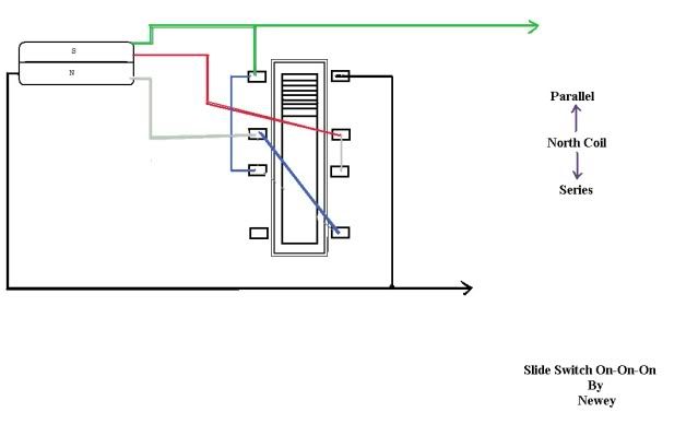 |
|
|
|
Post by thelastguitarist on Dec 20, 2011 8:23:25 GMT -5
Newey thank you for the diagram - sorry i've not been back in a while but unemployment sudddenly got in the way of wiring guitars  GFS annoyingly do not include specs saying whther the pup is North or south coil. It's the 8k Bridge I'm using in the neck position - I'll email them and ask if there's not a simple test that can ascertain the polarity? I've got all the parts mounted on the guard now so ready to get to work on this. One thing - using Neweys options for the HB and in tandem with the single, AND with the remaining options on the other mustang switch, can I have one setting that bypasses the tone and voilume and sends all pup signals straight to jack? and can I still include the phase options? |
|
|
|
Post by thelastguitarist on Dec 20, 2011 9:03:16 GMT -5
EDIT: The single lippy has red and white wire. if that helps
|
|
|
|
Post by newey on Dec 20, 2011 18:46:27 GMT -5
Nope, it doesn't. I'll have to go back and look at that, work is calling me tonight so it may be a bit . . . There is, and no need to email GFS. Simply de-mount (I know, I know, you just mounted them . . .  ) the SC pickup and hold it up against each coil of the HB, holding the string side of the SC to string side of the HB. With only 3 coils, we don't need to know absolute polarity, just need to know which one of the 3 coils is the "odd man out". Your SC will attract one HB coil and repel the other. For hum-cancelling, we want the N coil to be opposite the HB coil being split- so just remember that "opposites attract". |
|
|
|
Post by thelastguitarist on Dec 21, 2011 9:08:16 GMT -5
Perfect tip - duly tested. I've ascertained which coil attracts and which repels now. How should I orient the HB - opposite attracting coil nearest bridge or furthest? I'm presuming here that the split active coil is worth sticking nearest bridge for a more lead/treble tone. I'm also assuming that if orienting it further from the bridge sounds better then the single coil pup will need to be turned upside down too? Just thinking out loud: feel free to state what the 'actual' case is!
|
|
|
|
Post by newey on Dec 21, 2011 21:42:58 GMT -5
For reference, the leads on a HB pickup generally go out towards the cavity, the leads point "downwards" in playing position. If the leads come out pointing towards your armpit while playing, it's generally "flipped".
Which one of the bridge coils is of opposite polarity to the neck coil, with both in their "normal" orientation? Then you can decide whether to flip it or not.
There's no right or wrong way. Although the majority of S-H guitars will use the two coils closest together, some folks want the closest to the bridge, for as much brightness and treble as possible.
|
|
|
|
Post by newey on Dec 21, 2011 22:29:46 GMT -5
Looking back through this thread, I don't know that we definitely heard exactly what other options there should be. Phase was mentioned, as was HOOP. Have you decided what you want to do with the second slide switch?
|
|
|
|
Post by reTrEaD on Dec 21, 2011 22:40:47 GMT -5
Phase was mentioned, as was HOOP. Are you talking about sHooP or pHooP? |
|
|
|
Post by newey on Dec 21, 2011 23:46:57 GMT -5
Well, since intra-pup series wasn't really mentioned, I was thinking pHooP. More specifically, I was thinking of something along these lines, but this is more a basis for discussion than an actual program until we hear more from TLG. 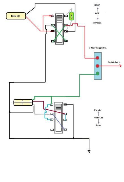 And TLG, I don't see how we can do phase and a bypass of the pots on one switch, I find myself needing another pole. Anyway, that's one idea for you. |
|
|
|
Post by thelastguitarist on Dec 22, 2011 7:20:18 GMT -5
Just checked my understanding of HOOP and sounds cool. The overall end results should be a series of options that all give decent usable tones so in my mind I would prioritise the top few most useful options within the limited number switch options i.e: If OOP has more limited use than direct-to-jack I'd opt for DTJ. I'm happy to go with recommendations on what actually constitutes most useful as I'm unable to try these first hand at this time to find out for myself. If once it's all wired and playable and I find a particular option that I don't get much use from I can certainly look to swap it out for an alternative in the future!
|
|
|
|
Post by thelastguitarist on Feb 14, 2012 6:43:32 GMT -5
ALMOST DONE!! Using Neweys schematic fom the other page. Took a shot at it and was amazed that i managed to make a working guitar! There still remains some questions about the shielding and grounding however (I'll come to that). but first here is many deatiled pics - i'd be grateful if you could give them the once over and check I've not made any schoolboy errors! Wiring 90% done! Still got to get some clarification form the good folks at Guitarnutz forum on grounding and shielding but IT WORKS. I'm posting loads of pics in case anyone can spot any issues. The whole thang: 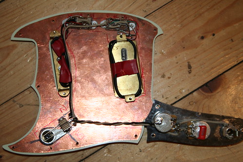 IMG_0126 IMG_0126 by Davemeister23, on Flickr 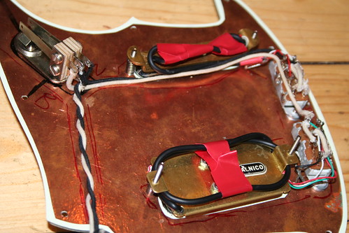 IMG_0117 IMG_0117 by Davemeister23, on Flickr The control Plate 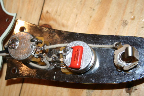 IMG_0116 IMG_0116 by Davemeister23, on Flickr The toggle 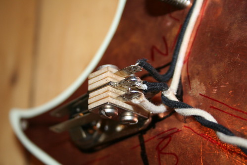 IMG_0118 IMG_0118 by Davemeister23, on Flickr Both switches, one side 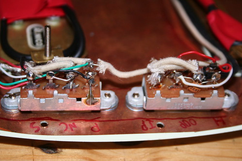 IMG_0121 IMG_0121 by Davemeister23, on Flickr Both switches other side 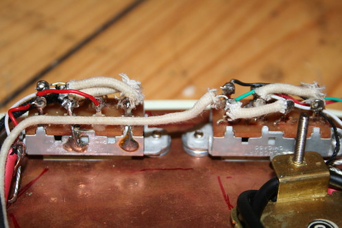 IMG_0122 IMG_0122 by Davemeister23, on Flickr Both switches above 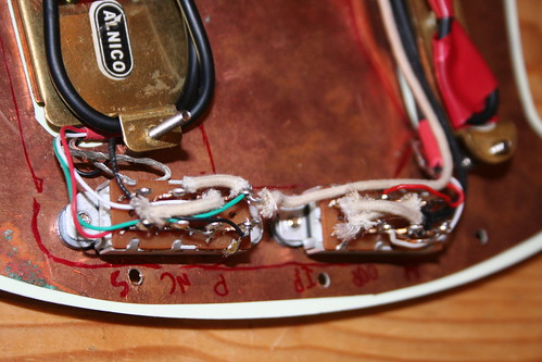 IMG_0119 IMG_0119 by Davemeister23, on Flickr SINGLE COIL Neck: IN PHASE, OUT OF PHASE, HALF OUT OF PHASE 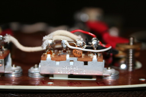 IMG_0131 IMG_0131 by Davemeister23, on Flickr Single coil: other side  IMG_0123 IMG_0123 by Davemeister23, on Flickr Single coil above 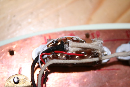 IMG_0124 IMG_0124 by Davemeister23, on Flickr HUMBUCKER: SERIES, SPLIT (NORTH COIL), PARALLEL: Above 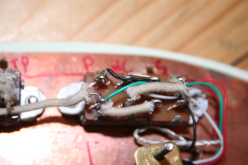 IMG_0125 IMG_0125 by Davemeister23, on Flickr Humbucker: another angle 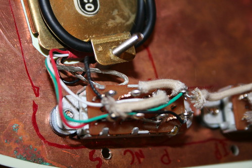 IMG_0120 IMG_0120 by Davemeister23, on Flickr The hand routed not yet fully shielded cavity. All fits fine. 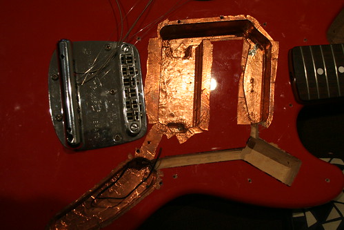 IMG_0128 IMG_0128 by Davemeister23, on Flickr Okay questions: 1) the pups have bare metal wires also. I've no idea what should be done with them - cut them off? Ground them? WHAT ARE THEY!!? 2) I want this to be grounded properly and have a fully shielded cavity. At the moment grounding occur on the switches....Do I need to change any of this to make the shielding a proper cage thingy? 3) There is a grounding wire from the bridge that pops out in the control cavity - where do I solder that in context of question 2? 4) I'm still unsure about the white and red wires on the single coid. GFS instructions are really odd. It sounds full and fine though so think I got it right. I'll dig up what they say and post later. 5) the cap on the single coil: i just took neweys schematic into our local maplins and pointed at the cap. you can see what they gave me in the photos - is that okay? |
|
|
|
Post by newey on Feb 14, 2012 7:07:06 GMT -5
Those are the shield wires. They are used to ground the frame of the pickups, and perhaps the covers if the pups are covered. They should be grounded to whatever point you are using for your ground point- looks like you're using the back of the V pot from the pickups.
I don't know what you mean by "grounding occur on the switches". The shielding has to be grounded, and ultimately all grounds need to be attached to the output jack negative lug.
It goes to the grounding point- see #1 above.
If it sounds full, you got it right. The odds were 50-50.
|
|
|
|
Post by thelastguitarist on Feb 14, 2012 11:21:47 GMT -5
Cool, well so far there are three places where grounding occurs. One is from the centre ground of the toggle and attached to the volume pot. Two others are lugs on the switches which have small wires from lug to the switch body. These are in the positions of the grounds shown on your schematic.
So if I understand correctly all grounds need to go to the jack ground. Now do I need to unsolder those grounds and run wires from them to the jack? Or, given that the switches and pots are all in metal contact with the copper shielding and control plate will soldering a wire from the shielding to the jack achieve the same thing?
I'm a little hazy about where I've soldered to the volume too - should I remove this and solder to jack instead or can I just add a second wire from pot to jack?
I suppose another way to ask this is what is the best, simplest way to finish off the grounding given where I'm at at this point?
|
|
|
|
Post by reTrEaD on Feb 14, 2012 12:43:27 GMT -5
"Ground" has two functions.
1 - a common path for signals.
2 - a path for current induced on electromagnetic shielding to flow to earth.
Wherever practical, it's best to keep these two functions separate until the lowest resistance path to earth. It's not practical to run a separate wire for the shields back to the amplifier. In some cases, it's even difficult to run a separate wire to join the two systems (signal common and shielding) at the output jack.
Keep the signal commons separate from the shielding points as much as possible. This is easier if you have 4 wire + ground wiring on your pickups. Avoid connecting the signal ground to the back of the pots, if possible. But if necessary, I think a single point (such as the back of the volume pot, is much better than multiple points.
|
|
|
|
Post by thelastguitarist on Feb 14, 2012 13:57:24 GMT -5
Thanks ReTread, I think I'm getting what you are saying. Caveat: I am a total layman here - its easiest for me to understand in idiot terms and in the practical context of this project. I.e: "Take all those switch and and pot grounds, desolder them and run wires to the jack. Then run the bridge ground and the shielding ground to the jack also" <---- that's just an example, not saying that's what your saying or event he right thing to do  |
|
|
|
Post by newey on Feb 14, 2012 20:29:49 GMT -5
I'll try to simplify what I, and reTrEaD are saying.
1) don't rely on the shielding to carry a signal ground, if the only grounds on the switches are carried through the shielding, then you should run those to a grounding point.
2) a grounding point can be to the back of a pot, like most manufacturers do it. But it can be difficult to get solder to adhere to the back of a pot, and too much heat, for too long, can destroy the pot. It's best to use a screw or nail into the sideof the cavity, through the shielding. This is then connected to the output jack negative, and all the grounds are connected there. This accomplishes what reTrEaD suggests, having only a very short run of wire where both the shield ground and signal ground connect together.
You can use a spade lug or a ring lug to solder the wires to, then the screw holds the lug to the shielding. That's how I usually do it.
If you are going to use the back of a pot for the grounding point, use a bit of sandpaper to roughen the surface, that will help solder adhesion.
Running many wires to the output jack is usually not practical, particularly in a Strat. Collecting all at a single grounding point, and then a short wire run to the jack negative terminal is the next best thing.
|
|
|
|
Post by reTrEaD on Feb 15, 2012 0:30:22 GMT -5
Thanks ReTread, I think I'm getting what you are saying. Caveat: I am a total layman here - its easiest for me to understand in idiot terms and in the practical context of this project. Sorry, I don't water fine points down. Read Newey's post. None of this will keep your guitar from working. You might get a bit more hum and noise, but it might not even be noticeable. It's a judgment call whether the best possible wiring practices are worth the effort, it they result in unmanageable clutter. 2) a grounding point can be to the back of a pot, like most manufacturers do it. But it can be difficult to get solder to adhere to the back of a pot, and too much heat, for too long, can destroy the pot. Good point. I suggest using a high wattage iron if using a puddle on the back of a pot. If it takes more than two or three seconds to melt the solder puddle, stop. Your iron is not hot enough. If it takes too long to get the solder to melt, you'll heat the innards of the pot and destroy it before you can make the connection. Some think that low-wattage irons prevent damage. But in this case, they will cause it. |
|
|
|
Post by thelastguitarist on Feb 15, 2012 6:30:59 GMT -5
Seriously guys, thank you so much for your patience and taking the time to clarify things. Okay I've read everything you say ans I'll now list, step by step, what I think I need to do to achieve what you guys have said is the ideal situation, starting from the ONONON switches. Hopefully I can be clear enough that if I'm wrong you guys can let me know. Refer to the photos and neweys schematic upthread if any doubt of the current situation:
1) ONONON switches
- Currently in contact with the shielding
- Currently these have lugs that take the grounds from the pups.
- The same lug currently has a wire connected to the switch body.
- The switch body is in metal contact with the copper shielding on the pickguard so this is the inefficient 'relying on the shielding to carry a signal ground' mentioned by Newey.
THEREFORE
- The best option is to remove the ground wire between the lug and the switch body and instead attach two lengths of wire to each switch ground lug. These will then be run down to the Toggle switch ground lug.
Questions:
- Does it therefore matter that the switch has metal contact with the shielding or is there a reason to remove shielding where the switch screws contact it? I assume not if I make the changes detailed above.
- Can I solder the bare metal wires from the pups to the same ground lug to ground the metal covers?
- should I remove copper shielding from around the Pickup screws as this creates contact between the metal covers and backs of the pups and the shielding thus 'relying on shielding to ground' as Newey pointed out.
2) TOGGLE SWITCH
- Currently this switch is in contact with the shielding which means the grounding lug is in metal contact with the shielding also - I deduce this again causes "relying on the shielding to carry a signal ground" mentioned by Newey.
THEREFORE:
- remove the shielding around the toggle so the toggle has no contact with it, which means the grounding for all switches runns only via grounding wires and does not connect with the shielding at this point.
- Attach the two ground wires from the ONONON switches to the centre ground lug on the Toggle. There is already the ground wire from that lug that goes to the Control Plate.
3) CONTROL CAVITY
- Currently The ground from the Toggle is soldered to the volume pot
- Currently the Volume Pot has one lug folded back and soldered to the pot, which I presume is a ground.
- Currently there is a ground wire that come from the bridge into the control cavity
THEREFORE:
- Desolder the Ground wire and the ground lug from the body of the pot.
- Take the Toggle ground wire, Bridge ground wire, and a ground wire from the lug and attach them all the a metal ring.
-Nail or screw that ring into the body inside the cavity.
- run another wire from that ring to the ground lug on the output Jack
QUESTIONS:
- Should the Ring have no contact at all with the copper shielding or is is sufficient that the screw enters the wood even though there is metal contact with the shielding?
-IF i do need to remove contact with shielding and the ring then presumable I need to solder a wire from the shielding to the ring?
- The shielding is in direct contact with the metal control plate on which the pots and Jack are mounted. Does this cause "relying on the shielding to carry a signal ground" from those pots and jack as mentioned by Newey. If so should I remove some shielding around the top of the cavity so that shielding does not touch the Plate OR maybe put plastic washers between pots/jack and the control plate but keep the connectivity of Plate and shielding?
THE RESULT, AS I UNDERSTAND THIS:
The shielding is effectively isolated and grounded separate from the switches all up to the Ring. These are then taken to the Jack ground.
PHEW. Sorry that's so long and detailed but for me to parse all this I need to think this through logically step by step until i 'get' the principals involved. Getting there slowly but surely. Thank you guys, I'm stoked with the the help and kindness you've shown on this forum.
|
|
|
|
Post by reTrEaD on Feb 15, 2012 7:34:03 GMT -5
Seriously guys, thank you so much for your patience and taking the time to clarify things. Okay I've read everything you say ans I'll now list, step by step, what I think I need to do to achieve what you guys have said is the ideal situation, starting from the ONONON switches. Hopefully I can be clear enough that if I'm wrong you guys can let me know. Refer to the photos and neweys schematic upthread if any doubt of the current situation: 1) ONONON switches- Currently in contact with the shielding - Currently these have lugs that take the grounds from the pups. - The same lug currently has a wire connected to the switch body. - The switch body is in metal contact with the copper shielding on the pickguard so this is the inefficient 'relying on the shielding to carry a signal ground' mentioned by Newey. THEREFORE- The best option is to remove the ground wire between the lug and the switch body and instead attach two lengths of wire to each switch ground lug. These will then be run down to the Toggle switch ground lug. Avoid using the toggle switch frame for signal ground, if possible. Questions:- Does it therefore matter that the switch has metal contact with the shielding or is there a reason to remove shielding where the switch screws contact it? I assume not if I make the changes detailed above. Correct. The metal frame of the switch becomes part of the shielding. - Can I solder the bare metal wires from the pups to the same ground lug to ground the metal covers? You should connect that to the shielding, rather than the signal ground. The frame of the switch would be an easy place to accomplish that. - should I remove copper shielding from around the Pickup screws as this creates contact between the metal covers and backs of the pups and the shielding thus 'relying on shielding to ground' as Newey pointed out. If none of the coil wires of the pickups are connected internally to the frame of the pickup, treat the frame of the pickup like part of the shielding. No need to remove the copper shield to prevent contact. 2) TOGGLE SWITCH- Currently this switch is in contact with the shielding which means the grounding lug is in metal contact with the shielding also - I deduce this again causes "relying on the shielding to carry a signal ground" mentioned by Newey. THEREFORE:- remove the shielding around the toggle so the toggle has no contact with it, which means the grounding for all switches runns only via grounding wires and does not connect with the shielding at this point. - Attach the two ground wires from the ONONON switches to the centre ground lug on the Toggle. There is already the ground wire from that lug that goes to the Control Plate. The switch part of the toggle doesn't use a connection to ground. The frame can be considered part of the shielding. If there is a need to connect any wires to signal ground, do this elsewhere if possible. Like the back of the volume pot or the output jack. This is where you need to use your own judgment. IF there are (-) wires of the pickup coils that need to be connected to signal ground, you might have to use the ground lug of the toggle as part of the signal ground if the wires are too short to go elsewhere. In that case, either treat the frame of the toggle as signal ground only and break the connection to the foil, then run a wire to where the signal and shield systems are tied together. OR make this a point where the systems are tied together and leave the foil in contact with the toggle frame. |
|


 ) the SC pickup and hold it up against each coil of the HB, holding the string side of the SC to string side of the HB.
