|
|
Post by newey on Dec 2, 2011 6:52:06 GMT -5
Dannyhill and I have taken his wiring problems to PMs so as not to clutter schematics further. The problem appears to be, in part, due to his having a bridge pickup which is potted and has the baseplate connected to ground internally, so that a separate frame ground can't be run. So I redrew this so as to have the bridge ground be at the base of the series chain. He had previously moved the phase switch to the neck pup, so now essentially all the switching is off of the neck and only the neck ground (for which he can run a separate frame ground) is lifted. I had also previously replaced the V and T controls for regular master V and T, so ignore Pete's original V and T arrangement. The pots are omitted from mine for clarity, it's just a simple master V and T before the output. But before he moves on to wiring it, will someone please check that I've correctly implemented the original schematic for this from pete 1234's original? THE ORIGINAL: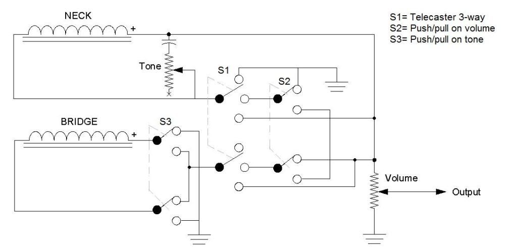 MY REVISED DIAGRAM: MY REVISED DIAGRAM: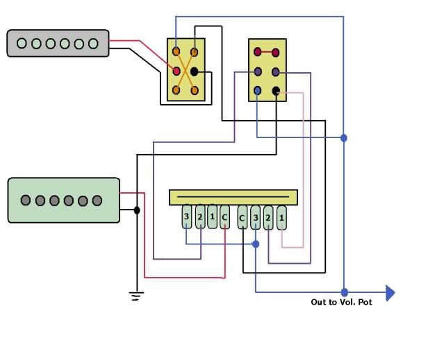 |
|
|
|
Post by asmith on Dec 2, 2011 7:07:13 GMT -5
I believe that that's correct.
Something I think should be mentioned though. Let's assume on the Neck pickup that red is hot and black is ground, as it is on the Bridge pickup. Also assuming that the Push/Pull pots are wired as if they are both correctly orientated and both "pushed/in" for standard mode, then Neck and Bridge are Out of Phase as standard.
That's a lot of assuming, but I wouldn't want it left unsaid.
|
|
|
|
Post by reTrEaD on Dec 2, 2011 9:49:25 GMT -5
That's a lot of assuming, but I wouldn't want it left unsaid. Worth saying fer shur. There's nuthin worse than doing the actual wiring and finding out all the wiring is functional, but your switches work in the opposite direction than you expected. I don't think "correctly oriented" is a good enough description. Some people orient their wiring diagrams as if the shafts of the pots are pointed to the top of the drawing. Others orient them as though then are pointed at the bottom (as if you are looking at the pickguard upside down on your workbench, ready to wire it). Your description of how the push pulls operate, tells me you orient your drawings like the first group of people. to newey: I find working with schematics to be much easier. A revised schematic would have been good intermediate step. But including the original still helped a lot, when trying to visualize the circuit. |
|
|
|
Post by asmith on Dec 2, 2011 11:10:26 GMT -5
I don't think "correctly oriented" is a good enough description. Some people orient their wiring diagrams as if the shafts of the pots are pointed to the top of the drawing. Others orient them as though then are pointed at the bottom (as if you are looking at the pickguard upside down on your workbench, ready to wire it). Salient point. It could be that they're drawn "shaft-down," and Danny wants Series mode as standard. The more I think about it, the more it seems like this will have already been thought of by Newey and he's way ahead of me.  |
|
|
|
Post by reTrEaD on Dec 2, 2011 13:29:06 GMT -5
Maybe Newey already thought about this. But are he and Danny both thinking the same way? When you have one person working out the details on the drawings and another person doing the actual wiring, clarifying "which way is up?" can save a lot of problems from arising. You may have saved Danny a ton of headaches by raising this question.  |
|
|
|
Post by newey on Dec 2, 2011 13:30:56 GMT -5
You're giving me too much credit, I hadn't thought of it and the wires should be flopped so that the in phase is with the P/P down.
It's always easy to hit a pulled-out P/P while strumming so its best for the least-used setting to be the "up" position, which of course here is the OOP position.
|
|
|
|
Post by reTrEaD on Dec 2, 2011 14:00:01 GMT -5
You're giving me too much credit, I hadn't thought of it and the wires should be flopped so that the in phase is with the P/P down. Hey, lookie thar! A little discussion and an overlooked detail was ironed out in the drawing stage. +1 to asmith! |
|


