|
|
Post by yakkmeister on Mar 5, 2012 8:37:26 GMT -5
I have been working on my Danelectro U2-56 re-issue (circa '98) and I have come across a little something I didn't quite expect... When testing the parts I noticed that the switch in the dano was an on/off/on type SPST. This threw me and I decided I had to be wrong so I checked a few times. I did a bunch of research and I discovered that the switch was, indeed, supposed to be on/off/on. So I wanted to make sure the wiring I did was up to scratch ... search after search later I found a few snippets here and there. What I compiled out of the various sources is the layout you (hopefully) see down below ...  My questions are... Will it work? Will the spst select Bridge in the 'up' position (respective to the diagram)? If I swap the 'hot' and 'ground' (not shield) leads on one of the pickup (inverting the polarity) will this make it sound 'thinner' or 'fatter'? (I suspect fatter, though I am unsure if these pickups are already inverted in respect to each other) Thanks, Yakkmeister. |
|
|
|
Post by reTrEaD on Mar 5, 2012 9:10:28 GMT -5
Hi yakkmeister, welcome to Guitarnutz2!
Dano used an on-off-on switch because they wired the pickups IN SERIES with each other. Most other companies wired their circuits to put the pickups in parallel with each other.
Your circuit has serious problems. You're trying to arrange your controls in the same way one would with a parallel arrangement and your pickups and switching like a series arrangement. This isn't gonna work well at all.
Having separate volume and tone controls for each pickup will be possible. But you'll need to do things differently than if the pickups were in parallel. To begin with, you'll want the switching after the pots. Also, you'll want the pickups connected to the outside lugs of the pots and the output will be taken from the CCW lug and the wiper. For at least 2 of the pots (serving the pickup on the top of the series chain) you won't be able to use the pot case as a common connection point.
Just like in the original Dano wiring, the switch will shunt half of the circuit to ground or hot for the single pickups, and allow the full series chain for the both pickup selection.
Also, in your drawing, the hot and ground lugs are backward from normal. Since you are looking at the rear of the pot, the clockwise end (if viewed from the front) would be on the left side.
Does this help, or are you feeling a bit lost at this point?
|
|
|
|
Post by yakkmeister on Mar 5, 2012 9:38:08 GMT -5
[EDIT!] Forgot to say thanks! (sorry!) I was with you right up until you said "Hi" ... JK! I did discover the series thing - that took a long time to make sense to me, but I got there. You're trying to arrange your controls in the same way one would with a parallel arrangement and your pickups and switching like a series arrangement. Yes - the concept of "what the things all do" was easy enough for me to grasp using this tone control (I believe it works by shunting signal to ground via a high-cut filter... sorta) and I could get a sense of "signal comes in here, does a thing then goes out ... there!" So that's the rationale as to why I used this arrangement - the the same as I used in my Canora 335 rip-off (humbuckers) and my Yamaha 112 Pac (Humbuckers, x3). I don't really understand the ins-and-outs, however. I suspect that removing the connection between the neck and bridge tone pots could help? Come to think of it ... the whole pot/switch assembly sits in a metal bracket, so it's all connected together... To begin with, you'll want the switching after the pots. Oh? I thought it was ... I read it like this ... Pickup --> Volume Pot [Shunt Some via Tone Pot] --> Switch I guess the idea was that the 'in' on the Vol pot was the 'hot' from P/Up ... Does that make sense? Also, in your drawing, the hot and ground lugs are backward from normal. I don't quite understand. I will colour-code my picture (cos, you know, that was totally not a good idea before? lol!) and see if it makes more sense? [EDIT 2]: Added Colour-Coded pic  |
|
|
|
Post by yakkmeister on Mar 5, 2012 11:45:42 GMT -5
I have been looking at this www.seymourduncan.com/pdfs/support/schematics/duo.pdfsome more (it formed the basis of my idea here) to see if I could figure anything else out ... I noticed I had some stuff backwards. Below is the updated diagram with a little 'pin-out' key to make pointing out my stuff-ups all the more simple ^_^  |
|
|
|
Post by reTrEaD on Mar 5, 2012 11:48:57 GMT -5
Oh? I thought it was ... I read it like this ... Pickup --> Volume Pot [Shunt Some via Tone Pot] --> Switch That's close. What you want is pickup -> tone -> volume -> switch -> jack You have the series link tied between the two pickups. That has to occur after the volume controls. And you have the series link as black to black on the pickup wires. Even if you only had one volume and tone and did the switching at the pickups, the series link should be black to red. Think of this the same way you connect two batteries in series in a flashlight. The cells are stacked with the positive of the bottom battery touching the negative of the top battery. This will work:  The pots and switch are shown as viewed from the rear. The same way you would view them inside the control cavity. |
|
|
|
Post by sumgai on Mar 5, 2012 16:15:40 GMT -5
I'm gonna ask ya if ya want a lifeline on that answer, or if yer gonna stick with it..... (Hint: think 'hanging hot'  ) Seriously, I know where you intended to go with this, but I think the wire colors got the best of you. 
And lest anyone thinks I'm getting forgetful in my old age..... yakkmeister, welcome to The NutzHouse! ;D sumgai |
|
|
|
Post by reTrEaD on Mar 5, 2012 16:39:02 GMT -5
I'm gonna ask ya if ya want a lifeline on that answer, or if yer gonna stick with it..... (Hint: think 'hanging hot' ) I'll stick with it, Regis. But if you have a better idea I'm all ears, as Ross Perot would say. |
|
|
|
Post by yakkmeister on Mar 5, 2012 21:16:42 GMT -5
I'm gonna ask ya if ya want a lifeline on that answer, or if yer gonna stick with it..... (Hint: think 'hanging hot' ) Seriously, I know where you intended to go with this, but I think the wire colors got the best of you.
And lest anyone thinks I'm getting forgetful in my old age..... yakkmeister, welcome to The NutzHouse! ;D sumgai Hanging hot? Is this because the bridge tone and volume pots have no path-to-earth thus, when the bridge p/up is 'earthed out' the 'hot' side is not tied down to anything? Thanks for the Welcome, much obliged.
So, reTrEaD; Thanks for the answer! I think I am getting a little better picture of how this all works... About the wire-colour thing ... Wouldn't it make no difference in terms of series/parallel if the coils were tied red/red, red/black or black/black? I understand it would function thusly when selecting middle: red/red [other parts and out] -> Black Wire -> Neck North -> Neck South -> Red Wire -> [Joined at sw] -> Red Wire -> Bridge South -> Bridge North -> Black wire -> [other parts & out] Black/Black [other parts and out] -> Red Wire -> Neck South -> Neck North -> Black Wire -> [Joined at sw] -> Black Wire -> Bridge North -> Bridge South -> Red wire -> [other parts & out] Black/Red [other parts and out] -> Red Wire -> Neck South -> Neck North -> Black Wire -> [Joined at sw] -> Red Wire -> Bridge South -> Bridge North -> Black wire -> [other parts & out] Since the middle position is 'off' this would mean that there is no other connection being made, tying one pole of the neck pickup to one pole of the bridge pickup. In my limited understanding, this would effect phase only. How far off the mark am I? Also ... I need to buy more parts! lol! |
|
|
|
Post by ashcatlt on Mar 5, 2012 21:51:27 GMT -5
There's no hanging hot with the bridge volume at one extreme or the other. In fact, the coil itself isn't directly connected to the hot output at all. At the middle of the resistance (not necessarily the middle of rotation) there's half a pot's with of resistance in either direction between the hot output and the coil. You've got a (relatively short) wire hanging from hot. Also, I don't see any way around it.
Yeah, the only difference between red>black and black>black or red>red is phase. Shrug. Do you want to get any low frequencies out of the middle position, or would you prefer to have mostly upper-mids?
I think retread assumed you your pickups were the same absolute string sensing polarity when wired the same way and that you were like most folks and would prefer the wide-spaced HB sound. SoOP is a pretty cool sound, but kind of special-effecty, and is quite definitely not the way it came from the factory.
|
|
|
|
Post by yakkmeister on Mar 5, 2012 22:09:56 GMT -5
There's no hanging hot with the bridge volume at one extreme or the other. In fact, the coil itself isn't directly connected to the hot output at all. At the middle of the resistance (not necessarily the middle of rotation) there's half a pot's with of resistance in either direction between the hot output and the coil. You've got a (relatively short) wire hanging from hot. Also, I don't see any way around it. Yeah, the only difference between red>black and black>black or red>red is phase. Shrug. Do you want to get any low frequencies out of the middle position, or would you prefer to have mostly upper-mids? I think retread assumed you your pickups were the same absolute string sensing polarity when wired the same way and that you were like most folks and would prefer the wide-spaced HB sound. SoOP is a pretty cool sound, but kind of special-effecty, and is quite definitely not the way it came from the factory. Makes sense. I was under the impression that retread was suggesting that the black/black was making it parallel as opposed to series, hence the confusion. I am after an in-phase, spaced coil configuration. Meaning that I definitely want to use retread's idea there! |
|
|
|
Post by reTrEaD on Mar 5, 2012 23:52:59 GMT -5
Makes sense. I was under the impression that retread was suggesting that the black/black was making it parallel as opposed to series, hence the confusion. I am after an in-phase, spaced coil configuration. Meaning that I definitely want to use retread's idea there! Okay, so it seems like Ash's explanation cleared up all or most of your misunderstandings? If anything is still unclear, feel free to say. Also, I don't see any way around it. Nor do I. Not with that switch, anyway. It could be done a bit cleaner with a 4PDT on-on-on switch but that's not what he has. The original Dano wiring had the two pickups in series and shunted neck, none, or bridge, depending on the position of the switch. This does the same but after the pots. SoOP is a pretty cool sound, but kind of special-effecty, and is quite definitely not the way it came from the factory. I think the Dano pickups are RWRP in a weird sort of way. From what I've heard, the guts are identical, but are flipped internally. Not just the magnet, but the whole coil wrapped around magnet assembly. With that in mind, in-phase would be a better choice in term of hum-canceling for this guitar. Like-polarity pickups hum-cancel when wired out of phase, so with a different pair of pickups that might be more desirable. I think that's why Brian May doesn't use a RWRP pickup on his Red Special. Since out of phase is inherently weaker, hum-canceling is even more important in the out of phase setting. |
|
|
|
Post by yakkmeister on Mar 6, 2012 4:23:14 GMT -5
Okay, so it seems like Ash's explanation cleared up all or most of your misunderstandings? If anything is still unclear, feel free to say. Not entirely. I understood his post, but not all of yours. Basically, I am not sure how the earthing works. I look at the schematic here and I can't figure out the signal path nor can I figure out exactly why the components are wired the way they are. I do understand the concept of series and parallel and how the Dano wiring is series and how the guitars I am used to are parallel. I understand how and why the p/ups in this diagram are wired in series (that is, the connection on the middle pin of the switch). Am I making sense? Nor do I. Not with that switch, anyway. It could be done a bit cleaner with a 4PDT on-on-on switch but that's not what he has. I have no problem ditching this switch for another if it means a better sound and/or simpler design. I would prefer to just use what I have, though, all things being equal. The original Dano wiring had the two pickups in series and shunted neck, none, or bridge, depending on the position of the switch. This does the same but after the pots. I think the Dano pickups are RWRP in a weird sort of way. From what I've heard, the guts are identical, but are flipped internally. Not just the magnet, but the whole coil wrapped around magnet assembly. Sounds about right ... en.wikipedia.org/wiki/Lipstick_pickupWith that in mind, in-phase would be a better choice in term of hum-canceling for this guitar. Like-polarity pickups hum-cancel when wired out of phase, so with a different pair of pickups that might be more desirable. I think that's why Brian May doesn't use a RWRP pickup on his Red Special. Since out of phase is inherently weaker, hum-canceling is even more important in the out of phase setting. I'm not interested in getting the OoP sound so I am happy to make a clean version of the original wiring, ie: series. |
|
|
|
Post by sumgai on Mar 6, 2012 14:22:35 GMT -5
yakkmeister, Don't let anyone scare you - you are on the right track, and you correctly understand more than you might think you do. But the diagrams posted so far all have one element missing, the fact that in series we must shunt individual pickups with their associated controls. That's not been done, so far. I humbly suggest that you consult some of the postings on this board by member wolf, who is into series wiring in a big way He also has his own website, www.1728.com, and there's quite a bit of guitar-related info therein. HTH
reTread, In the immortal words of D2o - "Don't make me come down there!" ;D sumgai |
|
|
|
Post by reTrEaD on Mar 6, 2012 14:42:59 GMT -5
I'm not interested in getting the OoP sound so I am happy to make a clean version of the original wiring, ie: series. Yeah, I figured you had your plan already solidified. I was just throwing that out there in a more general sense for anyone else who might be reading. I have no problem ditching this switch for another if it means a better sound and/or simpler design. I would prefer to just use what I have, though, all things being equal. I'd wire it with the SPDT on-off-on switch you have now. The 4PDT on-on-on is more expensive and add a little complexity. At worst, you might have a little more hum and noise when in the Neck only position. At best, the difference won't be noticeable at all. Not entirely. I understood his post, but not all of yours. That doesn't surprise me. Ash speaks more clearly than I do. Basically, I am not sure how the earthing works. Earthing serves two functions. A common connection and reference point, and a place to connect shielding where electromagnetic hum and noise can be diverted to earth rather than the signal carrying wires. In the case of your wiring, you'll have two common connection points, one for each pickup and controls. But only ONE of them is connected directly to earth. The other (bridge) common is a sort of "intermediate" common. In the Bridge only selection, it is connected to ground via the switch. In the Neck only selection, it's connected to hot via the switch. In the Both selection, it's half way between hot and ground. The drawing below will likely make this clearer than what I've just said. I look at the schematic here and I can't figure out the signal path nor can I figure out exactly why the components are wired the way they are. What we've been dealing with are wiring diagrams, not schematics. They look like physical representation of the parts. Good for doing wiring. Not as good for understanding the interconnections. Below is a group of schematics for different series and parallel arrangements, as well as a single pickup and controls "module". I think the schematics will make it easier to understand how things fit together. Two important notes:The selector switch is different in the series and parallel diagrams.The switch used in the series circuit has an OFF position in the middle. The switch used in the parallel circuit connects BOTH outer lugs when in the middle position. The switching strategies are different in the series and parallel diagrams.The series strategy has the pickups (or systems) pre-wired in series and uses the switch to short out whatever part isn't needed. The parallel strategy has the pickups (or systems) disconnected and the switch connects whatever part(s) that is(are) needed. 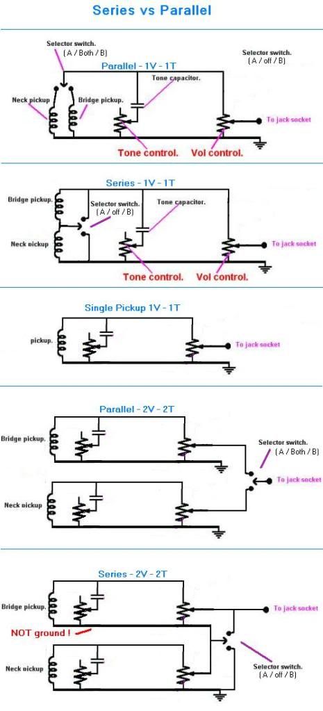 Are things clearer now? |
|
|
|
Post by ashcatlt on Mar 6, 2012 15:49:23 GMT -5
But the diagrams posted so far all have one element missing, the fact that in series we must shunt individual pickups with their associated controls. That's not been done, so far. is that your final answer there sg? retread's diagram in reply #4 exactly matches the last schematic in reply #13, and they both do exactly what you seem to be suggesting. And wolf's a great guy, and an asset to our community and the Internet at large. I have to humbly submit, though, that I've got 6 guitars with series options. In fact all of my finished guitars include series wiring, some in multiple different iterations. |
|
|
|
Post by yakkmeister on Mar 6, 2012 16:31:07 GMT -5
Holy carp! That's perfect! Thanks  As for that Wolf guy, I have used his website to wire up several guitars already - I went there first for this. See, I figured I could just follow a diagram I dig up someplace (like I did for this the first time I did it (and I did it wrong ...)) and just get the guitar working *OR* I could try and nut it out for myself. You guys have all been great help and I feel I am much closer to the solution ... I've uni and some work stuff to get onto today so I will post another modified wiring diagram when I can! |
|
|
|
Post by reTrEaD on Mar 6, 2012 17:14:49 GMT -5
Holy carp! That's perfect! Thanks  I've uni and some work stuff to get onto today so I will post another modified wiring diagram when I can! k, koo see ya soon. I have to humbly submit, though, that I've got 6 guitars with series options. In fact all of my finished guitars include series wiring, some in multiple different iterations. 6? That's nutz! Of all the possibilities in common wiring designs, pickups in series seems the most overlooked. With lipsticks or other pickups that are sort of thin on their own, it adds a lot of beef. Also, I like the way multiple controls don't interact when in series the way they do in parallel. Volume controls don't fight each other when rolled down to zero. And the tone controls only affect the pickup they are assigned to. |
|
|
|
Post by ashcatlt on Mar 6, 2012 17:41:30 GMT -5
the tone controls only affect the pickup they are assigned to. That part isn't quite true. Turning down the tone on one allows the treble from the other to bypass the inductance of the first. One pickup gets darker while the other gets brighter and the whole character of the sound changes. We call it broadbucker, half-series, or half-parallel. I have two guitars that do this. And yes, 6, with two more just waiting for me to order some switches. |
|
|
|
Post by reTrEaD on Mar 6, 2012 18:22:54 GMT -5
the tone controls only affect the pickup they are assigned to. That part isn't quite true. Turning down the tone on one allows the treble from the other to bypass the inductance of the first. One pickup gets darker while the other gets brighter and the whole character of the sound changes. Good point. I guess it's all in how you look at it. Locally, turning the tone down on one pickup doesn't change what's happening at the other pickup. But from a system view, it allows the other pickup to contribute its treble as if the first pickup was never in the picture at all. One thing's for sure. 2 tone controls in a series configuration are a ton more useful than 2 tone controls in a parallel configuration. |
|
|
|
Post by yakkmeister on Mar 6, 2012 20:14:20 GMT -5
I was thinking about posting a holy carp pic myself ... but I like the one you chose!  |
|
|
|
Post by sumgai on Mar 6, 2012 23:08:22 GMT -5
reT, Had to +1 you for that explanation in P. 13, complete with visuals - good job. I'm sure we'll all get over the hurdle I'm "carping" about, that last diagram in your posting - it'll just take a bit more time, tha's all. sumgai |
|
|
|
Post by sumgai on Mar 6, 2012 23:17:48 GMT -5
ash, Yes, the diagrams in Posts 4 and 13 are the same - both not quite up-to-snuff. In fact, you yourself noted such: There's no hanging hot with the bridge volume at one extreme or the other. In fact, the coil itself isn't directly connected to the hot output at all. At the middle of the resistance (not necessarily the middle of rotation) there's half a pot's with of resistance in either direction between the hot output and the coil. You've got a (relatively short) wire hanging from hot. Also, I don't see any way around it. You just pointed out some serious loading issues, which is what I've been alluding to. OK, one last attempt - just as with switches, in series wiring you shunt each pickup individually with the controls. That Bridge Volume's middle terminal going to the output.... doesn't that raise any red flags for anyone else here?  I mean, the Bridge Vol control acts more like a mixer at this point, which I don't think was the original intent of a separate Volume control.... Alright, here's another clue - to shunt a two-pole device, one needs only a.... 'nother two-pole device! As in, not a three-pole device. Gawd I hope I don't have to go on a spelunking expedition, rooting around in the cellar to see if I can dig up an Unklmickey post from 2006 or 7 or sumpin'..... my search-fu is getting weak, sorry to say.  And for the record, wolf has changed/re-written quite a bit on his site's guitar pages. I'm fairly certain that he's still a Series Wiring advocate par extraordinaire, but several of his older diagrams are now MIA, else I'd link to the one I recall he used to have, explaining what I'm talking about.  HTH sumgai |
|
|
|
Post by ashcatlt on Mar 7, 2012 1:51:10 GMT -5
I haven't read those old threads in a while, and I'd love to reminisce for a while.
I've been staring at the thing, though and can't find a more satisfying solution. You seem to be nodding toward that Bridge Volume pot. I can see two ways to re-wire it.
1) Swap the left-hand lug with the wiper. Then we're shunting the coil to itself. In series mode, that also puts the full resistance of the pot in series with the neck alone when it's turned down all the way. In bridge only mode it essentially leaves the jack open and buzzing. I don't like any of that.
2) Move both of those wires to the wiper and make it a variable resistance. I've read a number of times how this works better in series siruations. Not going to do what we want in bridge only mode, though.
Neither of these options sounded any better than the other until I found the hanging hot.
BTW I found the hanging hot. Sorry about that.
So, we need another pole or two on the switch to swap from pot to variable resistor, or something. Apparently I forgot to eat today...
Will have to think about this later.
|
|
|
|
Post by yakkmeister on Mar 7, 2012 2:21:20 GMT -5
Mmm ... this is getting very interesting indeed!
I am very interested in what all this adds up to ...
|
|
|
|
Post by reTrEaD on Mar 7, 2012 9:21:55 GMT -5
Mmm ... this is getting very interesting indeed! I am very interested in what all this adds up to ... I'm thinking the old military term "clusterf**k" might apply here. lol |
|
|
|
Post by ashcatlt on Mar 7, 2012 11:03:43 GMT -5
Well, since I'm the one who said there isn't a hanging hot, and since hinting around about it won't get us any closer to a solution, I'll go ahead and point it out.
I was actually pretty close in the same post where I said it wasn't there. When the bridge volume is all the way down the jack tip is connected directly to the "series connection" wire, which is connected to the black wire from the bridge pickup. The other end of the bridge coil is connected to the other end of the pot, which is enough resistance to basically consider it as hanging unterminated. The bridge pickup is kind of hanging "upside down" from the hot output. It'll make just as much noise hanging by its toes as by its fingers.
I still don't see a satisfactory solution with the existing switch. A 4PDT on-on-on will probably get us there.
|
|
|
|
Post by reTrEaD on Mar 7, 2012 12:43:07 GMT -5
The bridge pickup is kind of hanging "upside down" from the hot output. It'll make just as much noise hanging by its toes as by its fingers. Agreed. But will it contribute significantly less noise if it is folded in half, hanging by it's fingers and toes? I'm not convinced. There's a mechanism here that no one has offered a decent explanation based on science. How does the signal induced on the "hanging" pickup get to the output? Only ONE end of it is connected (to hot). The other is just connect to ... nothing. If we apply conventional circuit analysis, that signal is meaningless. Yet we know there is some effect caused by having extraneous junk hanging from a signal carrying wire. I am FAR from convinced that shunting a pickup will make more than a slight amount of difference, if any at all. If someone wants to post soundclips or measurement data, I'm all ears. But the explanations I've read in the past, don't convince me at all. I still don't see a satisfactory solution with the existing switch. A 4PDT on-on-on will probably get us there. But at what cost? And I'm NOT talking about the price of the switch? In the Neck only position, it's simple and direct to disconnect the Bridge pickup system entirely. Whether or not there would have been a problem, it's now out of the loop. We weren't using the Bridge pickup, so removing it costs us nothing (other than a more expensive switch and a bit more effort in wiring). But in the Series position, we need to look at what we're accomplishing and what that the cost is. Even if you subscribe to the speculation that shunting the bridge pickup solves the problem (I don't), look at what we have to do to get there. If we connect the wiper to the CW lug (only in series mode), the Bridge volume control doesn't act like a proper volume control. The shunting severely affects the tone of the bridge pickup, long before there is a significant reduction of the volume. The loading of the volume pot rheostat kills the highs from the bridge pickup, but has very little effect on the lows from the bridge pickup until the rheostat has less resistance than the internal resistance of the pickup. So in addition to the severe tonal devastation of the bridge pickup's contribution, the overall volume contribution of the bridge pickup isn't reduced until the Bridge volume knob gets close to zero. Is this better? -- Disconnecting extraneous shiz that isn't needed, whenever possible/practical? YES! -- Shunting a coil to reduce noise from a hanging pickup? Serious doubts. -- Raping control functionality to accomplish an "improvement" that MIGHT be effective for a problem that might be relatively minor to start with? More than serious doubts about that one! If I were building this, I'd use a 4PDT switch to disconnect the Bridge pickup system when it wasn't involved. IF I happened to have one handy. Else I'd use the existing switch. But even with a switch upgrade, I wouldn't turn the Bridge volume pot into a rheostat in the series mode. As always, YMMV. |
|
|
|
Post by ashcatlt on Mar 7, 2012 14:13:16 GMT -5
The other end of the bridge pickup is capcitively coupled to every source of electromagnetic radiation in the universe. I pretty well convinced that it will be a noise source. Shunting the coil does help, and I've got several guitars which prove that. I was actually planning to record a bit of a test, but that's gonna be a few days out. I can say now though that my main gigging axe sits by default with all three pickups in series and two turned off (shunted) and I haven't noticed any side effects. Maybe my recording test will show me something I just haven't noticed before (never having actually bothered to A/B it), but i doubt it.
Smoke break's over. I'll be back.
|
|
|
|
Post by reTrEaD on Mar 8, 2012 0:16:58 GMT -5
The other end of the bridge pickup is capcitively coupled to every source of electromagnetic radiation in the universe. I pretty well convinced that it will be a noise source. Okay. But if that's true aren't both ends of the of the pickup capacitively coupled to that same source? Shunting the coil does help, and I've got several guitars which prove that. I was actually planning to record a bit of a test, but that's gonna be a few days out. Whenever you can get to it, I'll be glad to listen to it. You'll have one part of the test with the end hanging loose and the other with it shunted to hot, right? I can say now though that my main gigging axe sits by default with all three pickups in series and two turned off (shunted) and I haven't noticed any side effects. Okay, but I'll assume your guitar has the switching before a single volume control, right? Any side effects there would be minor compared to having a shunt style volume control. I decided to try my hand at 5spice. I have two circuits modeled. One has a pickup (source, resistance, inductance, and capacitance), normal volume control, and simulated cable and load. The second has the volume control configured as a shunt. With each I ran two sweeps. One with the volume from 100% to 10% resistance, the other from 10% to 1% resistance. Since the sweeps can't have anything other than equal steps, you can't simulate a log pot. But even as they are, these graphs give me grave concerns about shunted pots. 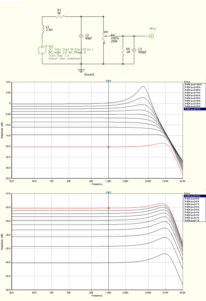  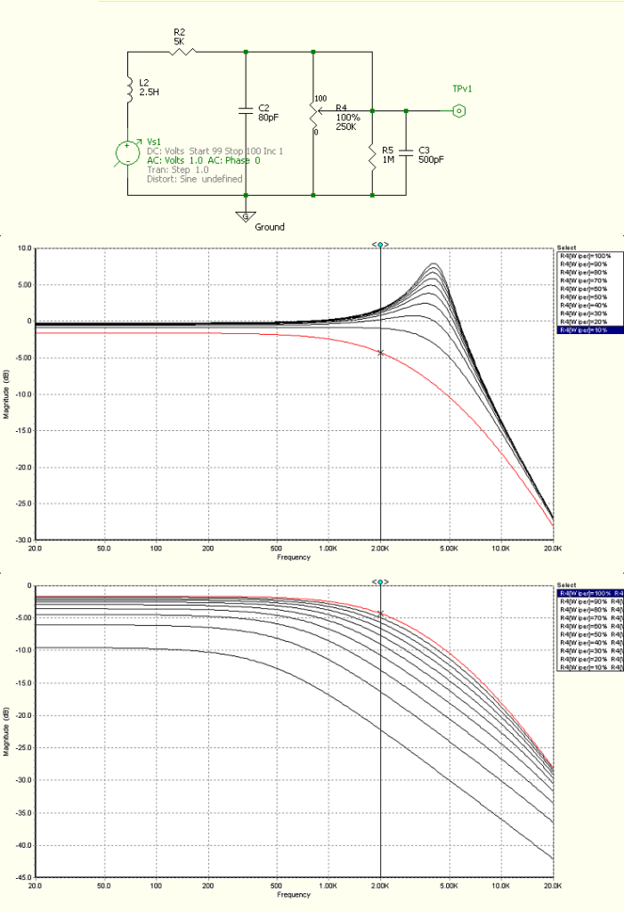  How bad would any hum/noise have to be, before you would be willing to make the bridge volume act like the bottom instead of the top? |
|
|
|
Post by sumgai on Mar 8, 2012 4:46:20 GMT -5
ash and 'TrEaD, You've both finally hit it - we want a variable resistor (a simple two pole device) across the pickup. As the SPICE chart indicated, this shouldn't create any spikes in the tonal spectrum, but that's before we include a standard tone circuit (treble cut) - that'll cause a bit of tone modification, but not objectionably so. When this is done, we also - automgtically! - eliminate the hanging hot issue. Nifty, no?
'TrEaD, The coil acts as an electromagnetic antenna, just like any other coil in existance. The noise contributed to our signal is pretty negligible for most players/guitars/venues, but there are some folks who, for whatever reason, do find it loud enough to be a problem. Thankfully, when a coil is shorted (in this case by the Vol pot turned all the way down), it effectively can't receive, and pass on, electromagnetic interference (QRM, in HAM-speak).  The Dreaded Tone-Suck issue is best left for discussion with JohnH. ;D
One other thought, especially for you, yakky.... Because you now have your pickups arranged in series, the combined inductance will likely cut down on some of your treble frequencies, just like what happens in a standard humbucker. The normal "cure" for that is to use a higher-value pot, or in your case, a pair of them. Ask someone to SPICE up a pair of 500KΩ units in your circuit, and see what the response curve looks like.... (Note: don't install treble-bleed circuits on either pot, the results have been reported to be undesirable by nearly every guitarist who's tried this.) HTH! sumgai |
|


 )
)


