|
|
Post by JohnH on Mar 8, 2012 5:40:38 GMT -5
Time to step in briefly ('cos I dont entirely agree):
Hanging from hot
....causes noise, but its not a show stopper. To understand the issues, try this test, with a guitar cable, an alligator clip wire, and an amplifier.
Turn up the amp, with nothing plugged in – it should still be fairly quite.
Plug in the cable, and if it is a good one, there will be a small amount of buzz but not too much. In this state, we have a long ‘hanging from hot’ cable, which is the inner core. But it is inside the outer grounded screen acting as a shield. Conclusion: Shielding is good
Connect alligator clip wire to the grounded outer part of the jack plug at the free of the cable. No difference, anything grounded makes no noise in this case.
Now move the alligator clip wire to the jack tip. It is now hanging from hot and adds a loud buzz because it is not shielded.
Now test the idea that shunting both ends of a hanging from hot item makes a difference. With one end connected to the tip, compare the buzz either with the other end also connected to the tip, or just clipped to the outer insulation nearby. Ie, physically, it is in the shape of a loop connected to the hot, but you try it both electrically connected as a loop, or not . The result is that they are the same, there is no difference in buzz whether or not the wire has both ends to hot or just one end. The hypothesis derived from this is that for a pickup, if you have a hanging coil whether or not you shunt it will not affect the buzz created, but short wires and shielding will help.
The way I see this, the hanging from hot item is like one plate of a capacitor, the other being the rest of the planet. Whether this element forms a loop in its local self is not relevant to the charges that are induced in it by outside emfs. rather, what is important is its overall phyiscal dimensions, and any protection it gets from shielding
My LP has a series option, and if the neck pickup is turned down when in series mode, so just the bridge is sounding, then it s ‘hanging from hot’ and there is a very slight additional buzz as compared to a standard bridge only setting. Its OK though, but worth avoiding when possible.
Series wiring with two volume controls
...works fine, with switching after the individual controls, as in the last diagram of post 13. All my series-wired LP designs work like this, but you must have treble bleed circuits on each pot. Then you can mix smoothly eg with one pickup on full and the other anywhere from zero to max, and there is no dull spot at any mid-range pot settings.
Cheers
John
BTW, I decline to comment on tone suck - it not being an issue at all IMO
|
|
|
|
Post by sumgai on Mar 8, 2012 15:30:51 GMT -5
John, Thanks for the above report, although I think it's overly simplified, but at this point, I'd be picking very small nits indeed. As we all agree, the additional noise is usually very small. However, I note that you say treble-bleed circuits are good, in this scenario. Since I never used series combinations of pickups in my rig, let alone multiple pots, I don't have any personal experience here. But I seem to recall that others have reported "sudden" shifts of tone, as they crank the Vol pot down (or up), and that we've discerned that this is due to multiple loading paths, and when the associated capacitor actually comes into play. Or have I mis-remembered all of that discussion?  (Wouldn't be the first time.  ) sumgai |
|
|
|
Post by reTrEaD on Mar 8, 2012 16:48:53 GMT -5
Or have I mis-remembered all of that discussion? (Wouldn't be the first time. ) Can't say what's happening in your noggin', but perhaps you may be remembering something you read about bad things that can happen when treble bleed networks are use with multiple volume pots in parallel[/]. |
|
|
|
Post by sumgai on Mar 8, 2012 21:28:22 GMT -5
reT,
Could be, could be..... Not that I need to know more, but let's not leave yakkmeister hangin' out onna limb here. Instead of just saying "they're good to go", I think our new guy deserves a bit more data on the subject - anyone want to lay it out for him?
Thanks!
sumgai
|
|
|
|
Post by yakkmeister on Mar 11, 2012 0:49:24 GMT -5
Quite a lot of action on this topic! I haven't had another look at this yet (in terms of re-drawing my wiring diagram) - still snowed under with uni and work... reT, Could be, could be..... Not that I need to know more, but let's not leave yakkmeister hangin' out onna limb here. Instead of just saying "they're good to go", I think our new guy deserves a bit more data on the subject - anyone want to lay it out for him? Thanks! sumgai That would be lovely ... Does it matter about the switching's position in the circuit? I imagine that the controls would want to be earthed out along with the p/up and, I guess, there is a potential for this to be better if the switching (shunt to earth) is done after the controls? I may or may not be completely lost ... lol! I'll be reviewing everything again later to get this into my head. Thanks all! |
|
|
|
Post by reTrEaD on Mar 11, 2012 1:46:29 GMT -5
Does it matter about the switching's position in the circuit? Yes. I imagine that the controls would want to be earthed out along with the p/up and, I guess, there is a potential for this to be better if the switching (shunt to earth) is done after the controls? - The metal case of all pot cans be earthed. - The CCW lug of the Neck pots can be earthed. - The shield wires of both pickups can be earthed. - The Black wire of the Neck pickup can be earthed. - The String ground can be earthed. - The CCW of the Bridge pots can NOT be earthed. - The Black wire of the Bridge pickup can NOT be earthed. - The wiper of the Neck volume control gets shunted to earth when the selector is in the Bridge position. - The common connection of the Bridge system gets shunted to hot when the selector is in the Neck position. - Nothing gets shunted when the selector is in the Both pickups position. Series wiring with two volume controls
...works fine, with switching after the individual controls, as in the last diagram of post 13. All my series-wired LP designs work like this, but you must have treble bleed circuits on each pot. Then you can mix smoothly eg with one pickup on full and the other anywhere from zero to max, and there is no dull spot at any mid-range pot settings. Treble bleed networks seem like they would help a lot when one of the volume pots is in the middle of its range. Not only for tone, but also to slightly reduce the output impedance. Maybe a 1nF or 0.86nF cap in parallel with a 150k resistor. yakkmeister, do you know what a treble bleed network is and where it is connected? |
|
|
|
Post by JohnH on Mar 11, 2012 2:03:39 GMT -5
Series wiring with two volume controls
...works fine, with switching after the individual controls, as in the last diagram of post 13. All my series-wired LP designs work like this, but you must have treble bleed circuits on each pot. Then you can mix smoothly eg with one pickup on full and the other anywhere from zero to max, and there is no dull spot at any mid-range pot settings. Treble bleed networks seem like they would help a lot when one of the volume pots is in the middle of its range. Not only for tone, but also to slightly reduce the output impedance. Maybe a 1nF or 0.86nF cap in parallel with a 150k resistor. Exactamundo! - 1nF and 150k |
|
|
|
Post by yakkmeister on Mar 13, 2012 21:43:10 GMT -5
|
|
|
|
Post by newey on Mar 13, 2012 21:56:20 GMT -5
yakky-
The SD diagram does not have the two pickups wired in series, but in parallel, and it uses a Gibson-style 3-way toggle rather than an on-off-on. The diagram's fine if you want parallel wiring, but I thought you were after the series Dano wiring.
I think the diagram by RT back a page here (post #4) is basically what you want, perhaps not optimal, but I don't know that the "hanging from hot" issue is a deal-breaker.
|
|
|
|
Post by reTrEaD on Mar 13, 2012 23:45:47 GMT -5
yakky- The SD diagram does not have the two pickups wired in series, but in parallel, and it uses a Gibson-style 3-way toggle rather than an on-off-on. Absolutely correct! I don't know who checks these drawings over at Seymour Duncan, but they have their head so far up their a$$ they could check their own tonsils. From the drawing:Really Seymour? Really? To the best of my knowledge, Danelectro NEVER wired lipsticks in parallel. Google image search led me to these:  Wrong Silvertone model number and the pots are mislabeled, but the wiring is correct. 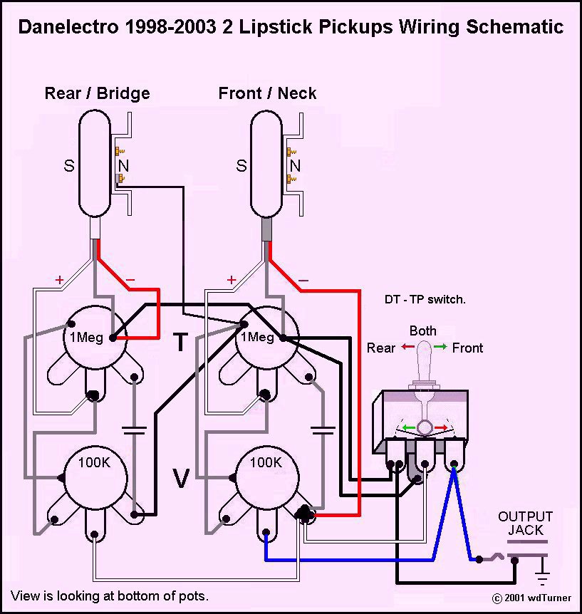 A little harder to follow, but I think the wiring is correct here, too. and this: image.aimoo.com/080122_120102_88484522.JPGto large to hotlink, and it's very hard to follow. |
|
|
|
Post by yakkmeister on Mar 14, 2012 9:31:42 GMT -5
Wow, I totally herped a derp on that one ...
Yes, I am going for the series wiring! Thanks!
reTrEaD - That first wiring diagram you posted looks very easy to follow!
Ok, so that solves the issue of how I am going to wire up this little dano ... in the next couple of days I am planning to re-read all the stuff you guys have so generously written for me and see if I can make sense of how it all fits. Once I have something of an idea, I'll post back here with how I think it works and also see if i can figure where a treble-bleed circuit fits into it ...
You guys ... just ... wow! So much knowledge! (and super-helpful too!)
|
|
|
|
Post by reTrEaD on Mar 14, 2012 15:08:34 GMT -5
Once I have something of an idea, I'll post back here with how I think it works and also see if i can figure where a treble-bleed circuit fits into it ... Look at the treble bleed thread by JohnH, stuck at the top of this forum. That will help. |
|
|
|
Post by yakkmeister on Mar 14, 2012 23:13:03 GMT -5
Once I have something of an idea, I'll post back here with how I think it works and also see if i can figure where a treble-bleed circuit fits into it ... Look at the treble bleed thread by JohnH, stuck at the top of this forum. That will help. Will do, thanks! ^_^ |
|
|
|
Post by yakkmeister on Mar 15, 2012 6:06:17 GMT -5
Ok, I think I have an idea of how this is supposed to work ... There are 2 main sections, each containing a pickup, a cap and 2 pots in parallel. Those sections are wired in series to each-other. When the switch is in one position, it connects the un-desired section, pickup and all, to earth on both ends, causing the signal to drop. I presume that the treble-bleed circuit will go across the middle and signal-out lugs (ie. not the ones that goes to ground) on both volume pots and in parallel in respect to itself?  So the left of the switch is one circuit 'section' and the right is the other ... The pot bodies would need to be connected up for good earthing and the ring on the jack would probably be best served by being wired up to those pot bodies, right? Also - inset is where I suspect the treble-bleed would go - I have omitted the purple/slate coloured wire (purple for the left, slate for the right) for neatness ... note that it's across the middle lug and the lug that connects to the cap. How'm I doing so far? |
|
|
|
Post by reTrEaD on Mar 15, 2012 11:10:50 GMT -5
Mostly good. The drawing is a little shaky looking, but it's almost correct. Move the wires that come from the right side of each pickup to the far right lug of the volume controls. The pot bodies would need to be connected up for good earthing and the ring on the jack would probably be best served by being wired up to those pot bodies, right? Yes. The volume pot on the left would be the most logical place to join all grounds together. Also - inset is where I suspect the treble-bleed would go - I have omitted the purple/slate coloured wire (purple for the left, slate for the right) for neatness ... note that it's across the middle lug and the lug that connects to the cap. This is correct. |
|
|
|
Post by yakkmeister on Mar 15, 2012 23:12:36 GMT -5
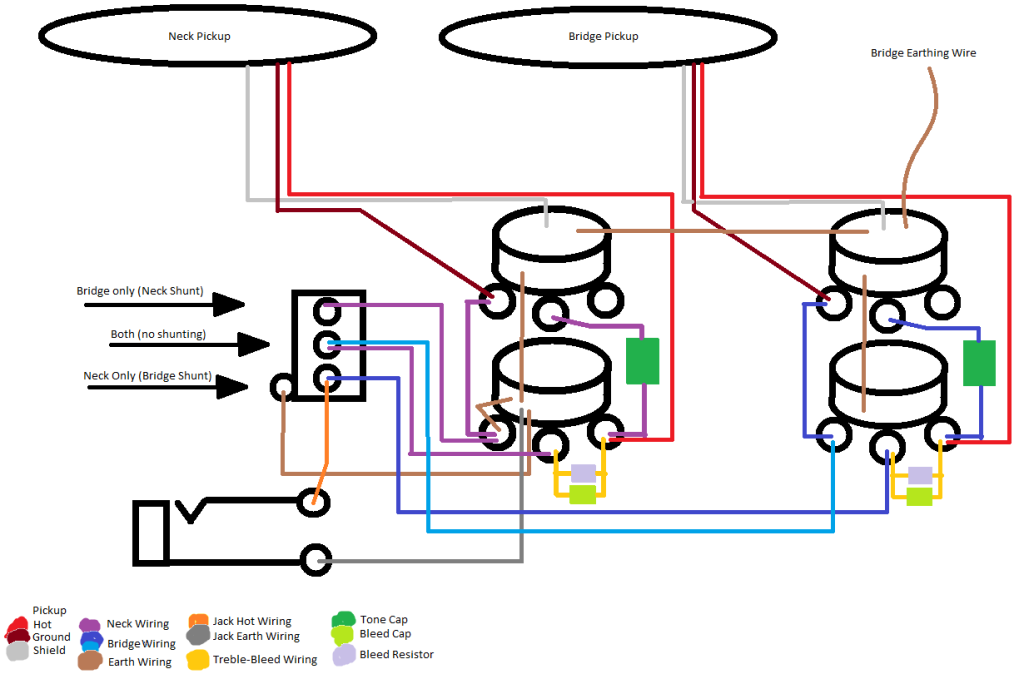 So this one has all the earth and shield wires represented along with the treble-bleed circuit in place. The switch has it's positions marked. In the 'bridge' setting, I expect to see continuity between the top pin and the middle pin ... right? Also, I expect the 'ground' and 'hot' wired from the pickup are fine as long as they are the same way around - if I were to reverse the ground and hot from one but not the other then it would be out of phase but if I reversed ground and hot from both pickups it would be be in phase and work as expected ... |
|
|
|
Post by reTrEaD on Mar 16, 2012 7:54:12 GMT -5
So this one has all the earth and shield wires represented along with the treble-bleed circuit in place. Good. I should point out that the way you have the pots drawn, the shafts would be coming out of the top. Obviously you wouldn't solder the earth wires to that face, but since the other face is obscured in the drawing, it's perfectly okay to draw them there, so you know they are connected to the case of the pot. The switch has it's positions marked. In the 'bridge' setting, I expect to see continuity between the top pin and the middle pin ... right? Yes. And the way a DPDT on-off-on toggle switch works, when the toggle is down, the continuity is between the middle and top as you have described. Also, I expect the 'ground' and 'hot' wired from the pickup are fine as long as they are the same way around - if I were to reverse the ground and hot from one but not the other then it would be out of phase but if I reversed ground and hot from both pickups it would be be in phase and work as expected ... A qualified yes to that. You have "hot', 'ground', and 'shield', for the pickup in the labeling at the bottom of your drawing. In this context, you are absolutely correct about the phase relationships you just described. You seem to be progressing well in your understanding of how this all fits together. I try to avoid the term 'ground' except to use it as a synonym for 'earth'. Else it can lead to confusion. But since your drawing is very specific about 'ground' meaning a particular coil wire from each pickup, there is no confusion. |
|
|
|
Post by yakkmeister on Mar 16, 2012 8:54:24 GMT -5
There are 3 parts to the hookup wires on my pickups.
there is a red 'hot' and a black 'ground' plus a woven, bare 'shield.'
What is the difference between 'earth' and 'ground' ?
I have always used them interchangeably ... shield, on the other hand, I get that it's not the same thing, though it's connected to ground (or earth?). I suspect it has something to do with forming a Faraday cage-like enclosure or something that conducts unwanted electromagnetic interference to ground instead of to the output.
The pots I have drawn have the shaft emerging from the bottom ... they're a weird stacked unit that I have only ever seen in this guitar.
|
|
|
|
Post by reTrEaD on Mar 16, 2012 9:41:02 GMT -5
There are 3 parts to the hookup wires on my pickups. there is a red 'hot' and a black 'ground' plus a woven, bare 'shield.' Yes ... sort of. More on this later. What is the difference between 'earth' and 'ground' ? I have always used them interchangeably ... Yes. shield, on the other hand, I get that it's not the same thing, though it's connected to ground (or earth?). I suspect it has something to do with forming a Faraday cage-like enclosure or something that conducts unwanted electromagnetic interference to ground instead of to the output. "Shield" refers to one specific function of the earth (or ground) system. Just as you have described. The other function is a "common" connection for the signal "return" path. In a circuit that pickups only connected in parallel, "common", "shield", "earth", and "ground" all connect to the same place. But your circuit has pickups in series. So things aren't quite the same. Labeling one of your coil wires as "ground" is slightly misleading. The "ground" wire of your neck coil is definitely connected to ground, always. But the "ground" wire of your bridge coil is only connected to ground when the selector switch is in the "bridge only" position. When the selector is in the "both" position, the "ground" wire from the bridge pickup is connected to a local "common" for the bridge pickup part of the circuit. That is not the same as ground for the whole system. The pots I have drawn have the shaft emerging from the bottom ... they're a weird stacked unit that I have only ever seen in this guitar. If that's the case, your pots will operate in reverse. When you turn them clockwise, the volume (or tone) will be reduced. If you have stacked pots, why not just use the Silvertone drawing in my earlier post and edit it slightly. 1 - Relabel the volume and tone pots, correctly. 2 - Move the right hand lead of each tone cap to the proper lug on volume pot instead of the selector switch. Electrically the same connection, but physically closer. 3 - Add the treble bypass components. |
|
|
|
Post by newey on Mar 16, 2012 9:53:22 GMT -5
As RT said, they are synonymous. What he was meaning about the use of the term "ground" (or "earth", for that matter), in the context of labeling wires in your guitar, is that it's confusing, and technically improper. "Signal return" is a better term.
We all call wires "hot" or "ground", "+" and "-"; these are convenient shorthands so long as we all recognize that they're not really "hot" or "ground" in any absolute sense.
But their use can cause confusion to those who don't know that we're using a shorthand, imprecise terminology.
|
|
|
|
Post by yakkmeister on Mar 16, 2012 10:55:09 GMT -5
why not use the other drawing? It's confusing. I could wire up the guitar just like that ... but if anything went awry, I would have no way to know how to fix it. Also, there has been a lot of effort to help me broaden my understanding of guitar wiring as a whole, I didn't want to waste that so I opted to draw my own. As for the shorthand of ground/earth, if I understand correctly, there is no real 'earth' in an A/C circuit, not in the same way as it's understood in a D/C circuit - half the time the electrons are flowing + to -, the other half they're going back - to +. In this case, I guess it's more correct to label them + and - to describe an A/C voltage relationship rather than a signal to earth relationship? So, I figure that by swapping the connection from one side of the pot to the other will correct the problem of rotation? I'll do another diagram up after I have finished saving the Galaxy...  |
|
|
|
Post by reTrEaD on Mar 16, 2012 12:41:16 GMT -5
I think the Silvertone drawing is less confusing, but whatever works for you is best. Making your own drawings does help require you to fully understand the circuit, so that part is always a benefit.
Swapping the wires on both ends of all pots will correct the rotational issue.
There definitely is a real 'earth' in AC circuits. But a problem occurs if you assume that an individual component can have one of its leads designated as 'earth' or 'ground'. Sometimes it can, sometimes (as in the case of your bridge pickup lead) it can't.
Labeling + and - works well. It indicates the phase, relative to each other.
|
|
|
|
Post by ashcatlt on Mar 16, 2012 12:59:42 GMT -5
I usually just say "top" and "bottom" when talking about signal carrying pickup wires.
Earth is the weird Limey way of saying Ground, so I guess they're interchangeable, though in my mind the term Earth at least seems to imply "Real Earth Ground". Like, the copper rod pounded into the actual ground outside your house. In AC mains wiring that is where ground is, and with voltages/currents in that range we definitely don't want to be using anything else as a reference point!
In DC wiring, circuit ground is usually connected to the most negative point - the minus side of the battery (or whatever power supply), but it doesn't really have to be. There is a class of guitar pedals (mostly fuzzes, I think) which are "positive ground" in that they use the + side of the battery as a reference point - even connecting the chassis shield to it - and all the action happens in the "negative" range.
There can actually be several grounds in a circuit. Back to pedals for a moment. There is usually a main circuit ground referenced to the bottom of the battery. You'll have the chassis and jack sleeves and stuff connected there. But then, at least for sections of the circuit, the audio signal needs to be referenced to a voltage somewhere in the middle of the power supply. So we have to provide a 4.5V point which is often called "VRef" (reference voltage) but is also sometimes (rightly) called "audio ground".
I'm hoping that hasn't now confused you worse, now that you seemed to be getting it.
The point is that all voltage is relative. It's very much like the distance between two points. If you want to know how long it will take to get from Duluth to New Orleans, it doesn't really matter how far each is from the Noth Pole. Sometimes, though, you might want to stop and rest halfway through, so you'd rent a hotel somewhere near St Louis.
Ummm... In general ground is a reference point to which all other voltages in the circuit are relative.
|
|
|
|
Post by reTrEaD on Mar 16, 2012 17:21:23 GMT -5
There can actually be several grounds in a circuit. Not sure what that means. In general ground is a reference point to which all other voltages in the circuit are relative. This is an important thought. |
|
|
|
Post by sumgai on Mar 16, 2012 20:22:35 GMT -5
There can actually be several grounds in a circuit.
Not sure what that means.It means that within a single given circuit, there can be several reference points for different purposes. Have you never encountered a diagram with markings for test points? Some of which are labeled "negative lead of meter here", or some such? And yet that point is not what we'd call ground (chassis or otherwise). Even in guitar amp-dom, we see troubleshooting charts (on schematics) that call out different "negative lead" points depending on whether your reading a DC or an AC voltage. How about solid-state power amps, particularly early ones. In the final output stage, you might see a honking-huge capacitor (or sometimes an inductor!) between the "common" legs of the push-pull stages and the speaker's nominal negative terminal - you certainly didn't connect that point to the chassis, not unless you liked spending moolah on replacing output transistors every time you flicked the power switch.  And yet this was called "common", which as we've all experienced, is often synonymous with the term "ground". An apt example of ash's point about "audio ground", though not the only one by any means. Hell's Bells, even John Atchley gets into the act - how else do you define the so-called "safety capacitor" lash-up? It's a separate ground for all the metal parts that the user might touch, and that ring washer is legitimately called a ground point, meaning that it's really a reference point for the shielding circuit. Generically, we've floundered off of The One True Path as delineated by ChrisK. Thereupon, Chris implored us to use the term "signal return" when we're referring to a pickup's signal that is connected to circuit points that we often label as "ground". Even I've dropped away from that terminology, sorry to say.  But that's because I don't want to confuse newcomers and/or electronics rookies with non-layman's terms. </confession> HTH sumgai |
|
|
|
Post by yakkmeister on Mar 17, 2012 2:29:04 GMT -5
So...
I have wired it all up with the pot connections corrected for rotation and the switching works great, the tone works well also ...
But I have no volume control!
The heck?
Edit: Ok, no tone either ... grr
Edit 2: There seems to be an open circuit over the bridge tone pot. that would explain why that side doesn't work ... and also cause me a lot of trouble as I am going to have to try and find stacked pots that will fit this ... being in Australia, that could be a problem...
|
|
|
|
Post by newey on Mar 17, 2012 6:02:44 GMT -5
Don't get frustrated, most rewiring needs a bit of troubleshooting.
Several of our members here are Oz- based , they'll have the skinny on concentric pots if needed. But what makes you think the pot is the culprit?
Most importantly, do you have a multimeter?
If both the V & T aren't working (I assume you mean you have no output when you're switched to the bridge pup), first thing to check are the signal return connections to the backs of those pots- since the two are tied together, a fault there could nix that whole side.
Also, a "quick fix" that often works is to just hit each of your connections on that side of the circuit briefly with your iron, enough to remelt the solder. Often, this will fix a "cold solder joint" or disclose a weak connection.
If you have a multimeter, more detailed troubleshooting can be done, and you can also check the pots to see whether they need replacing before spending your money. One or more bad connections are the more likely scenario, however.
|
|
|
|
Post by yakkmeister on Mar 17, 2012 6:41:12 GMT -5
-Yeah, I know - frustration doesn't really help. This guitar has been a very long time in the making - the bridge itself took the better part of 9 years to source (mostly because of limited resources but it was out of production for about 2 years, at least). So the prospect of more waiting is getting a little old I'll be taking a little break form this to get back into a useful state of mind - plenty of mates with guitars that need fixing Turns out the pots can be had through Allparts. There's a group in NZ that I get heaps gear through and they sell Allparts stuff. I also noticed they sell the dano toggle as well! Mine's been weird recently, very hard to move the bat ... though when changed, it does what it is supposed to. Yeah, I have a DMM. I was testing for continuity around the circuits, checking the joints and so on ... I tested the tone pot (1Meg Ohm) for resistance... all other pots read their appropriate values but this one read open. I could not find a short anywhere, though I suspect that is what must be happening ...? I actually get signal - it's all-on all-the-time. It's like the pots have been totally bypassed. I will do the re-heating the joints thing tomorrow - I am technically at a very large party right now ... priorities, right |
|
|
|
Post by reTrEaD on Mar 17, 2012 19:11:36 GMT -5
I'd suggest troubleshooting with an ohmmeter. You won't even need to take the guitar apart. Connect the leads of the ohmmeter to the loose end of a guitar cable, plugged into the guitar.
Tone controls shouldn't affect the reading. You might see a change while they are being rotated, but the reading will settle back to the original level wherever the control is stopped.
Put the selector switch in the "both" position, with both volume controls at max. You should read approximately twice the internal resistance of one pickup. Expect 10,000ish ohms.
Slowly rotate one volume control counter-clockwise. The reading should increase substantially. Eventually reaching about 1/2 1/4 the rated resistance of the volume pot. Continuing further counter-clockwise to minimum, the reading should be approximately 1/2 of the original reading.
With the first volume control now at minimum, start rotating the second volume control counter-clockwise. The reading should increase as before to about 1/2 1/4 of the rated value of the pot. Continuing counter-clockwise to minimum, the reading should drop to near zero.
If your readings don't follow this pattern, post your results. We might be able to determine where the problem is.
Edit: corrections made in red. (Thanks, John)
|
|
|
|
Post by JohnH on Mar 17, 2012 19:33:57 GMT -5
Slowly rotate one volume control counter-clockwise. The reading should increase substantially. Eventually reaching about 1/2 the rated resistance of the volume pot. Careful there! Usually the measured resistance of a guitar with pot at 50% setting is around 1/4 pot resistance plus a bit. This happens at 6-7 on a log pot. If there are treble bleed resistors involved however, the max is less again. John |
|


 (Wouldn't be the first time.
  )
)


 And yet this was called "common", which as we've all experienced, is often synonymous with the term "ground". An apt example of ash's point about "audio ground", though not the only one by any means.
 But that's because I don't want to confuse newcomers and/or electronics rookies with non-layman's terms.