|
|
Post by yakkmeister on Mar 21, 2012 22:58:13 GMT -5
Dear Legends,
Looking to build a Tele with the S1 ...
I have been unable to find suppliers for the switches themselves, I assume I can get those from fender ... but any tips on an alternative source would be appreciated...
What I would really like to know, however, is if the fender switching arrangement is optimum for a tele... I expect that I would only really need to add a treble-bleed circuit to it (that and some comprehensive shielding) and that would pretty much fix up any real issues with electronics... yes?
Cheers peoples!
|
|
|
|
Post by reTrEaD on Mar 22, 2012 1:06:25 GMT -5
pander much? lol Never bought an S1, but google led me to this. www.allparts.com/Fender-S-1-Switch-Parts-s/454.htmWhat kind of pickups on that tele? Just two single coils? I suppose you could go the S1 path, but I'd be more inclined to do a 5way superswitch. |
|
|
|
Post by yakkmeister on Mar 22, 2012 1:50:49 GMT -5
Me pander? Nah...
Gah! I fail at searching today ... I even looked on AllParts ...
I'm looking at the tonerider hot classic set (It's an option on the kit I am getting) so we're looking at 2x single coils.
What is the advantage of the superswitch over the s1 in a tele? I have a friend who has an American Standard Tele that was modified with the S1 arrangement and it sounds really nice, hence the idea to go with it. I suspect that the 5-way SS option is going to have the same options as the S1 but make them available on the one switch instead of splitting those options between 2? That would be rather useful from a usability standpoint ...
[Edit]
Perhaps this could be used to do switch phases and/or parallel/series? Could be super-messy though ...
mmm ...
|
|
|
|
Post by newey on Mar 22, 2012 5:40:57 GMT -5
The "S1 switching arrangement" to which you refer is unclear. Fender, as far as I am aware, uses the S1 on AmDlx Strats only, where it does several things in a three pickup guitar. It gives some series combos, it gives other combos with a "special cap", and also gives you the bridge pup (with the cap) without a volume control at position 3 of the 5-way.
None of that would be directly applicable to a Tele. SO, if your buddy has modified his Tele with an S1 switch, what does his do and does he have a wiring diagram you can use?
I suspect that, if the S1 were used with a regular Tele 3-way switch, you would be able to get both pickups in series at position 2, with positions 1 and 3 giving the pups individually through the "special cap".
Not sure if other options would be possible or not. We do have the pinout diagram for the S1 posted here, so other schemes using it can be figured out. But your buddy may have already invented the wheel. why reinvent it?
|
|
|
|
Post by newey on Mar 22, 2012 5:54:17 GMT -5
Learn something new every day- apparently Fender does use the S1 switch in a Tele, the "La Cabronita". This gives various selections of caps when the S1 switch is engaged. The S1 apparently functions as a Volume pot, there is no tone pot and the tone selections are fixed via the S1 switch. It also uses a Gibson-style 3-way toggle instead of the standard Tele switch.  I had never seen this model before, apparently it's something John Mayer plays and seems to be all the rage over in the Fender Lounge forums. |
|
|
|
Post by gumbo on Mar 22, 2012 6:22:46 GMT -5
..although I never chose to take my interest any further from a Tele standpoint (mine being a 72 Custom, anyway)... I think I remember S-1 switch Tele-style control knobs being available for quite a long time....  ...so I just assumed someone had figured out a way to make use of the circuitry..... I do seem to (also) remember a lot of comments in times past about the fragile nature of the S-1 switch itself....  |
|
|
|
Post by reTrEaD on Mar 22, 2012 10:34:52 GMT -5
What is the advantage of the superswitch over the s1 in a tele? Cost, availability, simplicity. "S1" by itself doesn't mean anything specific other than a 4PDT push-push switch on a potentiometer. There are different ways to use that. In the Classic Player Baja Tele support.fender.com/service_diagrams/telecaster/014-1502A_SISD.pdfFender is using the switch as a phase switch as well as employing a cap in one of the pickup selections. They use a 4way rather than a 3way pickup selector, so pickups in series is made possible by means of the pickup selector. In other guitars, they use the S1 switch to enable pickups in series. I wasn't aware of the circuit Newey posted, but there's another example how an S1 switch might be employed. Not sure what your ultimate goal is, but a superswitch can do some very good things with two pickups. It's possible to include pickups in series, parallel, and out of phase. We have 6 possibilities: Neck Bridge Neck and bridge (parallel) Neck and bridge (series) Neck and bridge (parallel) out of phase Neck and bridge (series) out of phase But since there are only 5 positions on the superswitch, it's only possible to wire for 5 of those. You'd need to eliminate one of the possible choices. It's completely up to you, but many would say parallel out of phase is the least important. Each of the five that you choose to keep can be assigned to whatever position you desire, when designing the wiring. Since we're dealing with a Tele, there are some limitations because of the size of the control cavity. To use a superswitch here, you'd need to enlarge the cavity or use a narrow version of the superswitch guitarnuts2.proboards.com/index.cgi?board=coffee&action=display&thread=6067&page=1 or use a Megaswitch-M. Not sure exactly what you had in mind, originally. Maybe using an S1 would fit better to your plans, maybe not. |
|
|
|
Post by yakkmeister on Mar 22, 2012 10:54:38 GMT -5
Hey guys, So that makes sense as to why searching S1 gives me no useful answers. My buddy doesn't concern himself with how things work ... he has no idea what makes it do what it does and I can't get at it to find out. Well, no matter ... From the different guitars that I have owned and what-not, I think that I would like to have a tele that does the following combos ... Neck Neck and bridge (parallel) Neck and bridge (series) Bridge I don't think I care to work out-of-phase so much ... However, let's say I applied a 4-way switch with the switching in the same order as the above list then added an S1 to invert the phase of the bridge pickup ... I could easily get the 4 more 'useful' tones and keep the out-of-phase gear off the main switch to make it easier? [edit] I'm an idiot. That's what you posted, reTrEaD. Ignore that bit ... [/edit] Now ... I say easier ... would that actually be a reasonable scheme? Would it be possible, and even useful, to have the S1 act as a kind of 'solo' switch - bypass everything and put both pickups on, no load, in phase and in series? That sounds like a fun button ...  Sorry I am so vague on this guys, I don't really have a clear-cut sound for this guitar in my head - I kind of want it to be a good, all-round rock/blues axe (I don't like country and I don't do shredding) that can still sound pretty when cleaned up. And I want to do this without humbuckers... |
|
|
|
Post by reTrEaD on Mar 22, 2012 14:02:30 GMT -5
From the different guitars that I have owned and what-not, I think that I would like to have a tele that does the following combos ... Neck Neck and bridge (parallel) Neck and bridge (series) Bridge That's easily covered by using a Tele 4way. You could use a 3way for the standard Bridge/Both parallel/Neck and S1 to accomplish the "both series", but the S1 is more expensive. Or you could use a 3way and a DPDT push-pull to get the "both series". I don't think I care to work out-of-phase so much ... However, let's say I applied a 4-way switch with the switching in the same order as the above list then added an S1 to invert the phase of the bridge pickup ... I could easily get the 4 more 'useful' tones and keep the out-of-phase gear off the main switch to make it easier? [edit] I'm an idiot. That's what you posted, reTrEaD. Ignore that bit ... [/edit] Now ... I say easier ... would that actually be a reasonable scheme? Yeah you could. But you could also use a cheaper DPDT push-pull to invert the phase of the bridge pickup instead of using an S1. So yeah, there are different ways of getting to the same combinations. Whatever suits your fancy. |
|
|
|
Post by reTrEaD on Mar 22, 2012 14:06:23 GMT -5
Would it be possible, and even useful, to have the S1 act as a kind of 'solo' switch - bypass everything and put both pickups on, no load, in phase and in series? That sounds like a fun button ... Probably. I haven't looked closely at that, but you have 4 poles on the S1. It seems pretty likely you have plenty of switch to accomplish all the tasks necessary for that. |
|
|
|
Post by newey on Mar 22, 2012 15:46:51 GMT -5
As gumbo mentioned, the rap on the S1 has been its fragility, as well as cost. So, if the scheme is doable with a regular DPDT push/pull, that would be the way to go.
Now, your idea for a "solo switch" probably would require more poles.
As RT mentions, a Superswitch™ in a Tele cavity will require you to hog out some wood from the side of the cavity to get it to fit. The Schaller Megaswitch or the narrow Superswitch are indeed alternatives; another option is the "Half Superswitch", which is exactly that, one-half of a Superswitch (i.e., 2P5T). That one does limit your wiring options a bit more than the others, but series/parallel options are possible with that- however, OOP would have to go elsewhere.
|
|
|
|
Post by yakkmeister on Mar 22, 2012 23:29:41 GMT -5
Oh, Neway, I forgot to thank you for that La Cabronita diagram - that looks kinda interesting ... It's got me thinking about this guitar's twin (to be built later ...) So I think the S1 is totally not worth the cost. I have a thing about over-complicating things (you may have noticed ... ) and I would really like to not over-complicate this build ... In that vein, what do you guys think about the following: Neck only Bridge + Neck - series (in phase?) Bridge only Bridge + Neck - series, bypass controls The idea would be that the guitar would be familiar in control scheme (like my dano) except that I can flick the switch back to open the output... Thoughts? Suggestions? |
|
|
|
Post by reTrEaD on Mar 23, 2012 1:31:49 GMT -5
Neck only Bridge + Neck - series (in phase?) Bridge only Bridge + Neck - series, bypass controls The idea would be that the guitar would be familiar in control scheme (like my dano) except that I can flick the switch back to open the output... Thoughts? Suggestions? I see what you're going for here and your reasoning. Nothing wrong with the idea, but I don't know if there is a switch that can do that. You need a bare minimum of one pole to do the pickup selection and two more to bypass the controls. That's three. A superswitch has 4 poles (one more than you need, but no problem) and 5 positions. I don't think there is a 4way version of that. A 4way Tele switch only has 2 poles. Not enough to accomplish what you want. |
|
|
|
Post by yakkmeister on Mar 23, 2012 2:09:41 GMT -5
Neck only Bridge + Neck - series (in phase?) Bridge only Bridge + Neck - series, bypass controls The idea would be that the guitar would be familiar in control scheme (like my dano) except that I can flick the switch back to open the output... Thoughts? Suggestions? I see what you're going for here and your reasoning. Nothing wrong with the idea, but I don't know if there is a switch that can do that. You need a bare minimum of one pole to do the pickup selection and two more to bypass the controls. That's three. A superswitch has 4 poles (one more than you need, but no problem) and 5 positions. I don't think there is a 4way version of that. A 4way Tele switch only has 2 poles. Not enough to accomplish what you want. Ok, let's assume I am somewhat crazy ... I took 2x 4-position switches and took them apart to make them into 1 switch ... could that accomplish the desired effect? What I expect would need to happen is that the wafer would be ganged on opposite sides of the lever with the shaft running through both. The second wafer would need the inner connections trimmed off or they'd contact the inner side of the first wafer... leaving 3 poles... I dunno ... I may have to get a couple and experiment ... I guess the other option would be a push-pull on the tone ... I've never been a fan of those - I find they are too easy to bump ... Mmm ... I can certainly live without the solo bypass thing, so a 3 way and the middle in series (like the dano) would be sufficient, I suspect (and hey, it's not gay if it's a 3-way! ). |
|
|
|
Post by reTrEaD on Mar 23, 2012 5:11:54 GMT -5
Ok, let's assume I am somewhat crazy ... I took 2x 4-position switches and took them apart to make them into 1 switch ... could that accomplish the desired effect? What I expect would need to happen is that the wafer would be ganged on opposite sides of the lever with the shaft running through both. The second wafer would need the inner connections trimmed off or they'd contact the inner side of the first wafer... leaving 3 poles... I dunno ... I may have to get a couple and experiment ... I don't think you will be able to fit the second wafer on the other side of the lever. That's where the detent mechanism is. Not the greatest pic, but I think you'll see what I mean:  I guess the other option would be a push-pull on the tone ... I've never been a fan of those - I find they are too easy to bump ... That or you could use a superswitch and have 5 choices. Maybe put the both in parallel selection at the opposite end from your both in series with bypass? |
|
|
|
Post by yakkmeister on Mar 23, 2012 6:02:39 GMT -5
Ok, let's assume I am somewhat crazy ... I took 2x 4-position switches and took them apart to make them into 1 switch ... could that accomplish the desired effect? What I expect would need to happen is that the wafer would be ganged on opposite sides of the lever with the shaft running through both. The second wafer would need the inner connections trimmed off or they'd contact the inner side of the first wafer... leaving 3 poles... I dunno ... I may have to get a couple and experiment ... I don't think you will be able to fit the second wafer on the other side of the lever. That's where the detent mechanism is. Not the greatest pic, but I think you'll see what I mean: [image removed] I guess the other option would be a push-pull on the tone ... I've never been a fan of those - I find they are too easy to bump ... That or you could use a superswitch and have 5 choices. Maybe put the both in parallel selection at the opposite end from your both in series with bypass? I do see what you mean ... Much less space than I anticipated. I think it's going to have to be the super-switch option then ... I will get one added to my parts order then ... ^_^ [edit] Looks like I won't be able to get the narrow kind without paying a metric butt-load of shipping costs. I'll live without bypass if the one lead I have on a potential switch doesn't pan out ... |
|
|
|
Post by yakkmeister on Mar 23, 2012 22:06:26 GMT -5
I woke up this morning with a crazy idea ... Pretty sure there's got to be some problem with it ... but here goes anyways. What if I used the common lug on the 4-way as the input-side? Then the selected lug would go to whatever circuit it needed to go to. 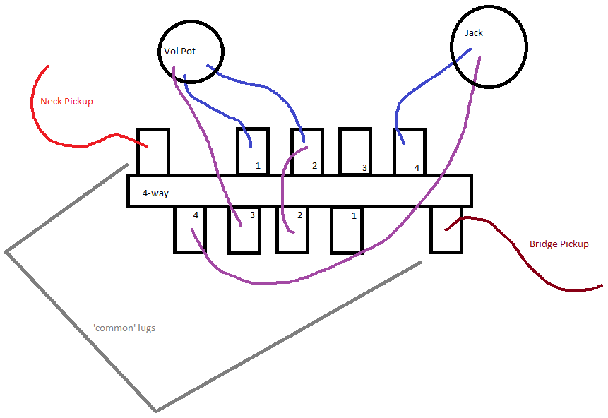 I don't think that diagram makes a proper series connection, heck, it's barely a diagram ... but I hope it makes the idea clear. Could that work to get the 4 options I mentioned before? I understand this is going to put a lot of stuff to wire in on that volume pot lug ... |
|
|
|
Post by newey on Mar 23, 2012 22:30:44 GMT -5
You're thinking along a productive path, many wiring schemes do that.
But your implementation, as per the diagram, has me scratching my head a bit. Your diagram may be too oversimplified. Should I assume, for example, that there is a connection from the volume pot to the jack + as well, not shown on the diagram? And, are the wires going to the circle labeled "jack" going to the tip connection? And the Vol pot wires are all connected to the CW lug of the volume pot, not to the back of the pot?
Even assuming those things, there's no series connection . . .
|
|
|
|
Post by yakkmeister on Mar 24, 2012 4:07:16 GMT -5
The diagram is super-exra-mega oversimplified.
There is no complete wiring diagram here at all - just the concept of the switch itself. I haven't considered how this will translate into the various options yet.
|
|
|
|
Post by reTrEaD on Mar 24, 2012 7:38:19 GMT -5
The diagram is super-exra-mega oversimplified. There is no complete wiring diagram here at all - just the concept of the switch itself. I haven't considered how this will translate into the various options yet. Exploring concepts is a good thing. It helps you understand what can and can't be done. And why. You might not be able to achieve the task at hand, but the knowledge you gain could help you in another application. You're thinking along a productive path, many wiring schemes do that. But your implementation, as per the diagram, has me scratching my head a bit. Your diagram may be too oversimplified. Should I assume, for example, that there is a connection from the volume pot to the jack + as well, not shown on the diagram? And, are the wires going to the circle labeled "jack" going to the tip connection? And the Vol pot wires are all connected to the CW lug of the volume pot, not to the back of the pot? Even assuming those things, there's no series connection . . . This points to some important elements in working out a concept. You need to consider what connections need to be made and broken and which connections that can be made at all times. Strat switches are harder to understand. In positions 2 and 4, the poles are connected to 2 throws. In the other positions, they're only connected to 1 throw at a time. One really needs to pay attention to understand how that can be used as an advantage and when it will get in the way. But the tele switch is much simpler. The pole connects to one throw and only one throw at a time. This is a great switch to start learning with. You could even draw the circuit as boxes representing key elements rather than all the components and all the wires connecting them. This can be less distracting. Then draw the poles of the switch as arrows indicating they can reach anywhere in the circuit. The throws will be little circles, to indicate that pole will make a connection here in a particular position of the lever. Be sure to note which pole that throw is associated with. In this case, the boxes would be [pickup system] [volume and tone controls] [output jack]. The first and last will have only one wire (don't need to draw the ground) but the box representing the volume and tone will have two wires. One for the input and one for the output. This will help identify where the pole(s) can (or must) be to accomplish the bypass task. Once we determine that part, we can move on to whether any of this switching can also help us with the pickup selection. Does this make sense, or should I draw you a picture? |
|
|
|
Post by yakkmeister on Mar 24, 2012 11:14:39 GMT -5
Pretty sure I get what you're saying ... But pictures always help  I have been jiggering away at about 16-million-billion different ideas and I think I need a solid "baseline" wiring scheme that will be awesome enough without the bypass 'solo' thing. Below is such an idea ... It's a 3-position switching arrangement and it's got the pickups in series with some old-fangled "50's" wiring arrangement with the volume/tone connection. 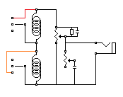 Viable? [edit] A version with a 'solo' switch ... 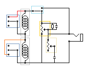 |
|
|
|
Post by reTrEaD on Mar 24, 2012 16:00:49 GMT -5
Pretty sure I get what you're saying ... But pictures always help I have been jiggering away at about 16-million-billion different ideas and I think I need a solid "baseline" wiring scheme that will be awesome enough without the bypass 'solo' thing. Below is such an idea ... It's a 3-position switching arrangement and it's got the pickups in series with some old-fangled "50's" wiring arrangement with the volume/tone connection.   Viable? The switching works, but it's wasteful. Two poles to do the same job that could be done with one. If you were using two poles for the purpose of disconnecting pickups when they weren't needed, I could see the point. But here, you're still just shunting pickups when they aren't in use. This could be accomplished with just the one pole that is already at the "series link" between the two pickups. I don't know how well that tone control will work when placed after the volume pot. The treble bleed network is made to reduce treble loss. Not sure if it will lead to some odd characteristics when the tone is rolled down. A version with a 'solo' switch ...   The solo switch does less than it needs to, imho. Since the wiper remains connected to the output jack, this will place a load on the pickup(s) if the volume was rolled down. And the tone control is still completely in place. This is how a bypass can be made to work where the position of the controls is completely irrelevant. 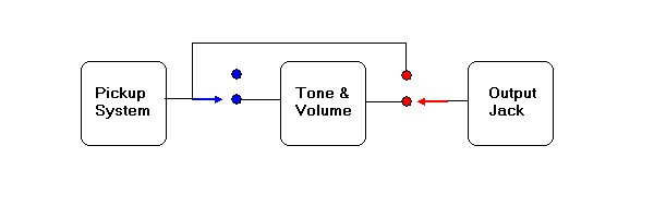  The controls are entirely disconnected from the circuit. However it does require two poles. |
|
|
|
Post by yakkmeister on Mar 24, 2012 20:01:45 GMT -5
Damn ... I spent ages trying to jigger it to work with just one and never came up with something that seemed to be right ... lol Back to the drawing board [EDIT] Just remembered the neat diagrams you posted about the Dano - found the answer! Ok - so it should come first then ...  This is essentially what I am trying to duplicate (the bottom one) in terms of relationship between volume and tone pots. |
|
|
|
Post by reTrEaD on Mar 24, 2012 20:48:15 GMT -5
Ok - so it should come first then ... This is essentially what I am trying to duplicate (the bottom one) in terms of relationship between volume and tone pots. Yes. The top part of that drawing show the tone control where it's normally located. When John tweaked the values for the treble bleed network, this is where the tone control was. The lower part of that drawing shows the tone control after the volume control. I have no idea how good or bad the interaction between tone control and treble bleed will be in that configuration. I took your earlier drawing and made a few changes to it. The upper left is the original The upper right uses just one pole The lower left uses two poles and disconnects the upper pickup when it isn't needed. 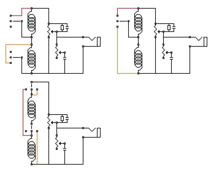  |
|
|
|
Post by yakkmeister on Mar 24, 2012 21:37:13 GMT -5
I am hoping this is closer to the correct way of doing it: 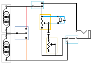 |
|
|
|
Post by reTrEaD on Mar 24, 2012 22:48:28 GMT -5
Two out of three switch sections are okay. The one in the bottom right is not so good. It isn't doing anything useful. In the bypass mode the pickups will be connected but they won't be connected in the normal mode. It would be best to replace that section with a junction of the three wires.
Use that switch section to connect the TIP of the output jack to the volume control wiper, in the normal mode only.
|
|
|
|
Post by yakkmeister on Mar 25, 2012 0:07:59 GMT -5
So I really should be disconnecting the un-wanted pickup then, not just shunting it?
I will have a go at positioning that bypass switch on the diagram you provided and see if I can get it right ...
Also - other than S1 or push-pull pots, what other viable option is there for the bypass switch? I hate push-pull pots, personally, and the S1 is stupid expensive. How would a no-load volume pot go as an alternative?
If push comes to pull (lol) I will opt for the S1 as it's not as obnoxious as a push-pull.
|
|
|
|
Post by sumgai on Mar 25, 2012 2:28:49 GMT -5
yakky, Let's revisit one of 'TrEaD's diagrams, you must've missed it along the way:  See those blue dots on the left? They don't make sense at first, do they? I'll explain as we go along. The first thing we're doing here is ignoring ground. You may correctly, and safely, assume that all three "modules" are grounded. Next, the output of the pickups is being switched by the blue portion of the switch between input of the controls module and nothing. One or the other, that's it. But note also that the pickup output is permanently tied to a wire that runs over to the red switch portion. Moving over to the red side, we see that the common red terminal goes to the 'hot' side of the output jack. That means that we can elect to send out either of two signals - whatever comes out of the controls, or the raw pickups themselves. But wait, you say, you could do this with just one switch pole, no? Yes, you could, but consider - the reason to bypass the controls in the first place is to have full output power from the pups, right? Then the question becomes, why continue to load those pups with the control section? By switching the both the input and the output controls module, we can eliminate it entirely from the signal path, thus giving us a 'true bypass'. Which of course means a signal with just about no load at all. Which is what we wanted all along.  BTW, that blue side of the switch? It's wired in this fashion in order to reduce the points of possible failure. The signal follows along one less junction point inside the switch. In general, that's considered a good thing, but it's not mandatory by any means. Now, go back (to your drawing) and insert the DPDT switch shown in 'TrEaD's diagram into your diagram (and removing that other one as noted by 'TrEaD above), and you should be good to go. ;D HTH sumgai |
|
|
|
Post by reTrEaD on Mar 25, 2012 4:59:04 GMT -5
So I really should be disconnecting the un-wanted pickup then, not just shunting it? That's a judgment call, really. If you have enough poles, I would. If you needed the extra pole to do something else, I wouldn't worry about disconnecting rather than shunting. I will have a go at positioning that bypass switch on the diagram you provided and see if I can get it right ... You have it half right. What you have right now looks like this, except for the ground switching thing you did with the second section of the switch. 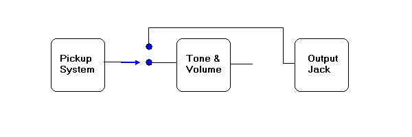  So put the ground system back to normal and use the second section of the switch to make the necessary connection when in the "normal" mode. The bypass part is already handled. Also - other than S1 or push-pull pots, what other viable option is there for the bypass switch? I hate push-pull pots, personally, and the S1 is stupid expensive. How would a no-load volume pot go as an alternative? You can't use a no-load pot for a volume control. If push comes to pull (lol) I will opt for the S1 as it's not as obnoxious as a push-pull. I can understand that. I'm not terribly fond of push-pulls myself. You can get push-push pots. The knob sits high, like a push-pull does when it's pulled. But you won't have the knob come off in your hand from pulling too hard, since you push down to engage and push again to disengage.~original |
|
|
|
Post by yakkmeister on Mar 25, 2012 5:46:33 GMT -5
Sometimes I wonder what's actually inside my head ...
lol!
Push-push looks like a good idea...
Yeah - I can't believe I didn't see that ... !!
I'll post again with a, hopefully, fixed diagram when I get home ...
Thanks!
|
|


