|
|
Post by ashcatlt on Apr 8, 2012 13:10:37 GMT -5
Now that's getting over my head a bit. Why is the inverting input drawing current through the bias resistors? Shouldn't that current be supplied by the opamp's output?
Honestly, my idea is pretty much stolen from the proco Rat circuit. It's got a 47 Ω in that spot and works just fine.
|
|
|
|
Post by reTrEaD on Apr 8, 2012 20:20:29 GMT -5
Now that's getting over my head a bit. Nah, I've read your posts. This isn't anything you can't master. It's just unfamiliar. Honestly, my idea is pretty much stolen from the proco Rat circuit. It's got a 47 Ω in that spot and works just fine. Apples and oranges, Ash. I'm not all that familiar with the Rat, but I'm sure it doesn't balance the supply the way this circuit does. Like most opamp circuits using a single supply, the negative terminal of the battery IS ground. Then they add caps all over the place to AC couple the signal. This circuit configuration is fairly uncommon. I've only seen it a few times. Imho, it's rather innovative, but there are details that require special attention. Why is the inverting input drawing current through the bias resistors? It isn't the input of the opamp that's drawing current. It's more a matter of current that must flow through Rin to achieve a voltage that's equal to the voltage at the non-inverting input. When those voltages are equal, the opamp is in balance. If the non-inverting input is more positive than the inverting input, the opamp output will try to reach the same voltage as the positive supply rail. If the non-inverting input is less positive than the inverting input, the output voltage will try to reach the same voltage as the negative supply rail. Shouldn't that current be supplied by the opamp's output? Yes, it absolutely IS supplied by the opamp's output. But that current needs a return path to the battery. If the opamp output is positive, the return path is through the lower "balancing" resistor. If the opamp output is negative, the return path is through the upper "balancing" resistor. I've indicated two of the currents involved, on the diagram below. The "idle" current through the balancing resistors (blue) and the current sourced by the opamp when the input signal is @ +100mV. I prefer to use conventional current in my analyses rather than electron flow, so note the direction of the arrows. 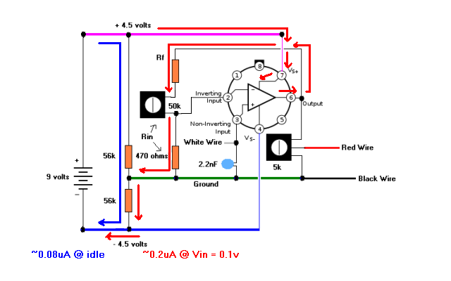  As you might guess, the relationship of the power supply rails is always changing with respect to ground, whenever a signal is applied. The total is always 9v, but the positive rail gets closer to ground and the negative farther from ground, when the output goes positive. (Vice versa when the output goes negative.) This is never an issue, until the voltage at one of the rails becomes less than the necessary output voltage. |
|
|
|
Post by ashcatlt on Apr 8, 2012 23:05:48 GMT -5
OK. I'm (kinda) following that. Still not sure I completely get it,or how it works in other instances, but we can work on that...
For now, the gain calculations are a function of the ratio of the resistors, and (if the real world doesn't get in the way) the actual values don't matter. So the resistor values I chose want to draw too much current. (Damnable real world!) So let's make them bigger. Will 4.7K resistors with a 500K pot work better? Seems to me like that would demand a tenth the current and cause a tenth the voltage swing. No?
|
|
|
|
Post by reTrEaD on Apr 9, 2012 0:36:56 GMT -5
Yes, scaling up the resistors will cure a lot of evils. The other way around would be to decrease the size of the balancing resistors. But that wastes current.
|
|
djeans
Apprentice Shielder

Posts: 46
Likes: 0
|
Post by djeans on Apr 10, 2012 21:46:37 GMT -5
Ok, I think I have everything I need and will start building the new one in the morning. There were several choices on the 50k pot, so I bought one of each. Any suggestion of which one i should go with?  |
|
|
|
Post by reTrEaD on Apr 11, 2012 5:47:55 GMT -5
Any suggestion of which one i should go with? If you're planning to mount everything on the switch, the trimpot is the logical choice. |
|
djeans
Apprentice Shielder
Posts: 46
Likes: 0
|
Post by djeans on Apr 11, 2012 18:32:25 GMT -5
I built it, with the new resistors and trim pot, and added the 5 k trim pot where i figured it would go.  But it doesn't quite sound right. The distortion kind of cuts out as the signal decays. Does that sound like you thought it would, or is something not right? djeans |
|
|
|
Post by reTrEaD on Apr 11, 2012 22:24:58 GMT -5
That does sound a bit off. Sort of "strangled" or smth. If you used this diagram as a basis, could you edit it to show the exact wiring? Erase as needed and add wires to show how things are connected at the switch. 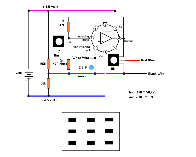  |
|
|
|
Post by sumgai on Apr 12, 2012 10:57:36 GMT -5
djeans, While yer at it, would ya mind doing us all a favor and reducing the size of your image, please? It's not the screen size that's an issue, it's how big the file is in terms of bits and bytes.... which in this case is over 3 Megabytes - Yikes!!  We do have some members who are still on dial-up, or almost as bad, need to log in from public places that limit bandwidth for whatever reason. This page is the slowest to load on our entire Forum, and I perceive that some viewers may not feel it's worth waiting for the Second Coming, if you get my drift. Who knows, that might be robbing you of valid participation by others viewers. Thanks! ;D sumgai |
|
djeans
Apprentice Shielder
Posts: 46
Likes: 0
|
Post by djeans on Apr 12, 2012 16:55:47 GMT -5
Will do. Didn't really think about that. Just posted them from my iPhone. I'll go through and reduce them all today when I get time
|
|
|
|
Post by sumgai on Apr 13, 2012 1:59:34 GMT -5
Thanks! ;D
|
|
djeans
Apprentice Shielder
Posts: 46
Likes: 0
|
Post by djeans on Apr 13, 2012 21:56:01 GMT -5
OK, Took me awhile, but I wanted to try to make it clean and accurate. I think (hope) I accomplished that. There was something labeled white wire that didn't match up with what I thought the original white wire connected to, I redrew it with how I have the wires connected. Hopefully this makes sense. D  |
|
|
|
Post by reTrEaD on Apr 14, 2012 0:51:14 GMT -5
Okay, so there are some problems. Hopefully there hasn't been any damage to the opamp. The connections to the switch cause the wiper of the volume pot to be connected to the input, loading the signal in bypass mode. That wouldn't damage anything, but it would make for a weak, dull signal in bypass mode. The connection of the opamp output to the switch caused a direct connection to the wiper when in boost mode. That means the only way to decrease the output is by shunting the signal to ground, instead of by voltage division. If the volume is set very low, this might cause permanent damage to the opamp. At the very least, it will sound pretty awful when shunted. Make the following change (lower half of the drawing). This should sound much better, if the opamp hasn't been damaged. 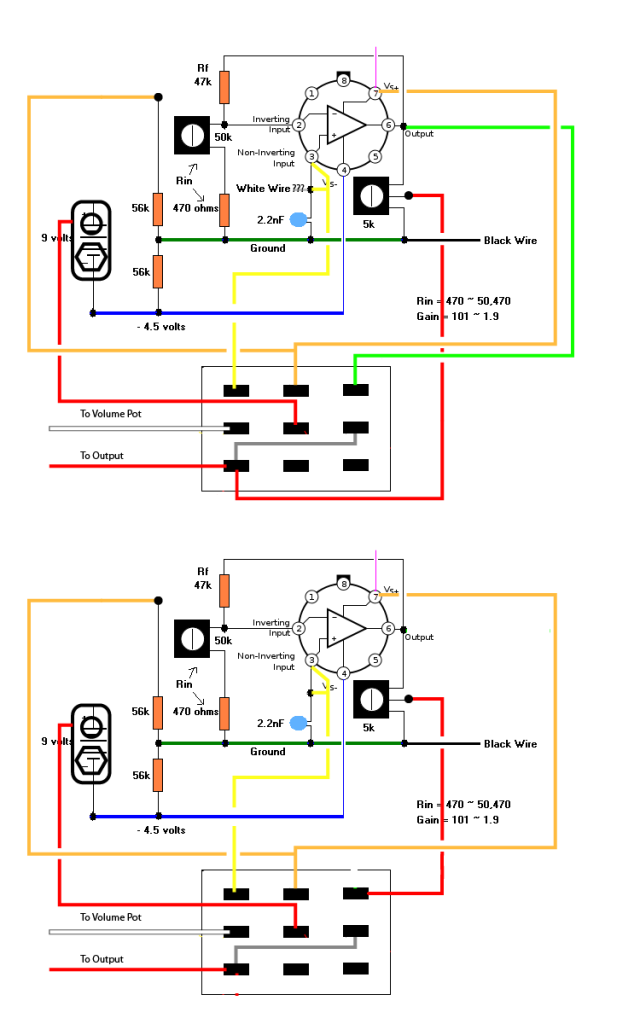 Use the gain control (50k pot) to get the desired amount of distortion (I think mild to moderate crunch might be better than heavy distortion) and adjust the volume control (5k pot) so the signal is noticeably, but not severely louder than the bypassed signal. |
|
djeans
Apprentice Shielder
Posts: 46
Likes: 0
|
Post by djeans on Apr 14, 2012 3:34:35 GMT -5
I may have fried the opamp, I made the changes, but it still sounds the same. It sounds distorted when on, but it's almost like there is a noise gate before the distortion. The sustain is noticeably lower than when in the bypass position. Notes die out very quickly, and when playing on the high E, unless I hit the string really hard, there's no sound at all when in the "on" position. Weird.
|
|
djeans
Apprentice Shielder
Posts: 46
Likes: 0
|
Post by djeans on Apr 14, 2012 21:55:02 GMT -5
I had a fresh opamp, so I tried pulling everything off the first one and switching it out for the new op amp. After putting it all back together, no signal in the on position. Weird. Everything looked connected right, but something must have been wrong.
|
|
|
|
Post by reTrEaD on Apr 15, 2012 21:22:13 GMT -5
It sounds distorted when on, but it's almost like there is a noise gate before the distortion. That seems like either a damaged opamp or perhaps too much gain along with an input offset issue. I would have suggested trying a lower gain setting, but you've already changed the opamp. |
|


