|
|
Post by JohnH on Jun 3, 2012 15:19:54 GMT -5
And you still can't have just one coil in system parallel mode. Not sure what you mean there - in normal parallel mode, you can select one pickup and one coil from that pickup? J |
|
|
|
Post by ashcatlt on Jun 3, 2012 15:28:31 GMT -5
And you still can't have just one coil in system parallel mode. Not sure what you mean there - in normal parallel mode, you can select one pickup and one coil from that pickup? J How? You switch one of the switches to an SC selection and then turn down the Volume on the other side and what happens? |
|
|
|
Post by JohnH on Jun 3, 2012 15:30:31 GMT -5
You could take this one step farther and incorporate some "automatic" hum-canceling. I'd use the right side of the top section for the bridge. Only on the HB local selector, you would direct the (-) of a single to system ground instead of to the 'D' buss. The (+) of the unused single is also directed to system ground while the (-) of the unused coil is directed to the 'D' buss. This swaps the two coils of the HB when the phase switch is flipped. You would still have all the same hum-canceling and non-hum-canceling pairs. But the hum-canceling pairs would always occur when the two local levers were synchronized. Probably clever - needs seeing on a diagram. The reason I put the bridge on the left, is that that becomes the hotter side of a series chain and if it is a covered pickup (which it might be but which the singles I assume wont be), then hanging issues are alleviated by the full shielding of the cover. John |
|
|
|
Post by JohnH on Jun 3, 2012 15:34:47 GMT -5
Not sure what you mean there - in normal parallel mode, you can select one pickup and one coil from that pickup? J How? You switch one of the switches to an SC selection and then turn down the Volume on the other side and what happens? Seems OK to me. The top part of the diagram has been built many times in other designs. |
|
|
|
Post by reTrEaD on Jun 3, 2012 16:20:48 GMT -5
How? You switch one of the switches to an SC selection and then turn down the Volume on the other side and what happens? I think you might be confused about the "series/parallel" switch (S2) and the pickup selector (S1). In the series mode, S2 overrides S1 to put the pickups in series no matter what position S1 is in. But in the parallel mode, the pickups aren't necessarily in parallel. S1 is a standard Gibson pickup switch. It doesn't look quite right on the schematic, but that's what it is. Drawing one properly is a royal pain, so you get used to seeing the kind of thing John is using to represent it. Middle position is pickups in parallel. But you can also select just the neck/middle "pickup". Or just the bridge HB. You wouldn't want to use a volume control to select the pickup. In parallel mode with both pickups selected, it has the classic Gibson wart. Either volume at zero kills all sound. In the series mode, the volume controls are more forgiving. One volume at zero will kill only the pickup that's assigned to that volume control. But you are correct about turning the left side volume control to zero. The right side pickup will work as normal but all the left side junk will hang from hot. Much better if you just switch to parallel mode and use the pickup selector to get the right side pickup. Probably clever - needs seeing on a diagram. The reason I put the bridge on the left, is that that becomes the hotter side of a series chain and if it is a covered pickup (which it might be but which the singles I assume wont be), then hanging issues are alleviated by the full shielding of the cover. John Yep, that makes perfect sense if you are using the option2 local switching. Not an issue with option1. The reason I would use the right side for the bridge is twofold. 1 - Swapping north for south within the bridge HB would be less confusing than swapping middle for neck. 2 - The unused coil will be shunted to ground on the right side. If we moved the phase switch to the left side, the unused coil would need to be shunted to the middle of the series link (in system parallel mode). I'll hack your drawing to show what I had in mind and post later. |
|
|
|
Post by ashcatlt on Jun 3, 2012 18:27:13 GMT -5
D'oh! I got tunnel vision a bit there and didn't even see sw1. Sorry bout that.
|
|
|
|
Post by reTrEaD on Jun 3, 2012 21:17:22 GMT -5
A Homer moment? Yeah I have those too. Here's a hack of John's schematic. 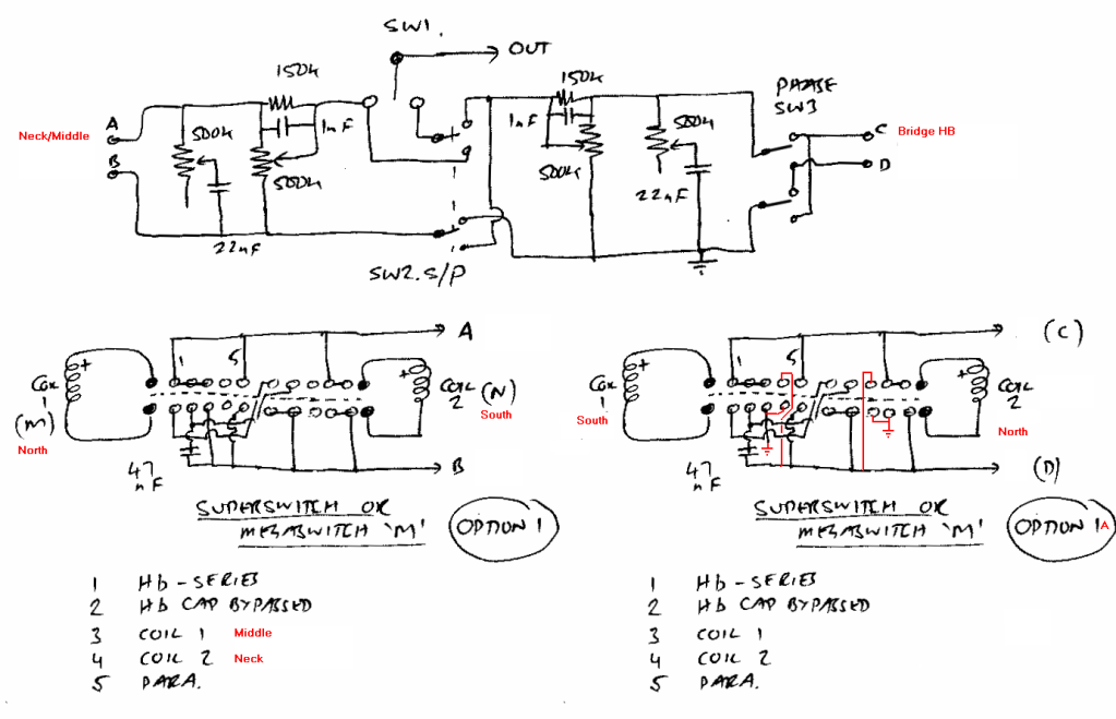  |
|
|
|
Post by JohnH on Jun 4, 2012 5:57:41 GMT -5
Here's a hack of John's schematic. Yes, a clever idea! I think, if there is a covered Hb, it is still worth placing it on the hotter side for series, even in the 5-way scheme. Although there are no unused hanging from hot coils in that case, it's still worth having the best shielding possible to active coils that are nearer to hot. And this phase/hum canceling idea I think will still work, putting bridge and phase switch on the left A-B side. Instead of the extra grounded connections to coils in your redraw, those connections will be to the colder side, point B. Now we are probably at a point where we need RW's considered views on switch type and pickup types, as well as order of the settings, then a wiring diagram to build from can be developed. cheers John |
|
|
|
Post by Runewalker on Jun 4, 2012 17:02:02 GMT -5
First, thank you gents for applying your considerable cortexes (cortexai?) to this notion of a design. I am always struck at what a true community this forum is. From pÉƎᴚ⊥Çá´š
How the heck is that pronounced? Pee-a-za Sasshikas? Wow. "…it would make sense if the singles were in the same position on both switches. If the north P-90 single was in the same switch position as the south single of the HB (and vice versa) the hum-canceling pairs would occur when the switches are both in the same position. At least for the in-phase pairs. …. But the hum-canceling pairs would always occur when the two local levers were synchronized….." I had not thought about that, but the array you describe would require less thinking while playing, and overwrought thinking is a condition with a poor prognosis of recovery. "...You could take this one step farther and incorporate some "automatic" hum-canceling. I'd use the right side of the top section for the bridge. Only on the HB local selector, you would direct the (-) of a single to system ground instead of to the 'D' buss. The (+) of the unused single is also directed to system ground while the (-) of the unused coil is directed to the 'D' buss. This swaps the two coils of the HB when the phase switch is flipped.
You would still have all the same hum-canceling and non-hum-canceling pairs. But the hum-canceling pairs would always occur when the two local levers were synchronized...."" Yes this goes in the direction I described earlier in making “automatic” preferred humcancelling selections. I am dense on understanding the “D buss” reference though. From John H:"...I think, if there is a covered Hb, it is still worth placing it on the hotter side for series, even in the 5-way scheme...." When the Midas was in the TM-II harness I covered the inside of the P-90 plastic cream covers with copper foil to obtain additional shielding. That harness though always had more hum than expected, and I never sat down and diagnosed the source. So while the Dimarzio P90 form-factor “Tone-Zone” is not a shield covered pup (has a plastic p-90 cover”) I could do that copper foil treatment. The rest of that exchange about the hotter and colder sides placements gets away from me. Now we are probably at a point where we need RW's considered views on switch type and pickup types, as well as order of the settings, then a wiring diagram to build from can be developed. Order of the SettingsI am still trying to understand the sound of the local Humbucker with cap bypass option. Is it a local series setting? Your description: " With the 5way, the Hb-cap bypassed, is a sound like a single coil, with added bass and a bit of a mid dip...." sounds like a local parallel sound with series Balzac... It sounds different to the ear than local parallel? Is it a "hear-able" difference to the local parallel? I ask because that affects the switching order of the 5 way. Pickup types:Bridge – Dimarzio Tone Zone P90™ , P210
www.dimarzio.com/pickups/soap-bar/tone-zone-p90
Specs
Wiring: 4 Conductor
Magnet: Ceramic
Output mV: 385
DC Resistance: 16.77 Kohm
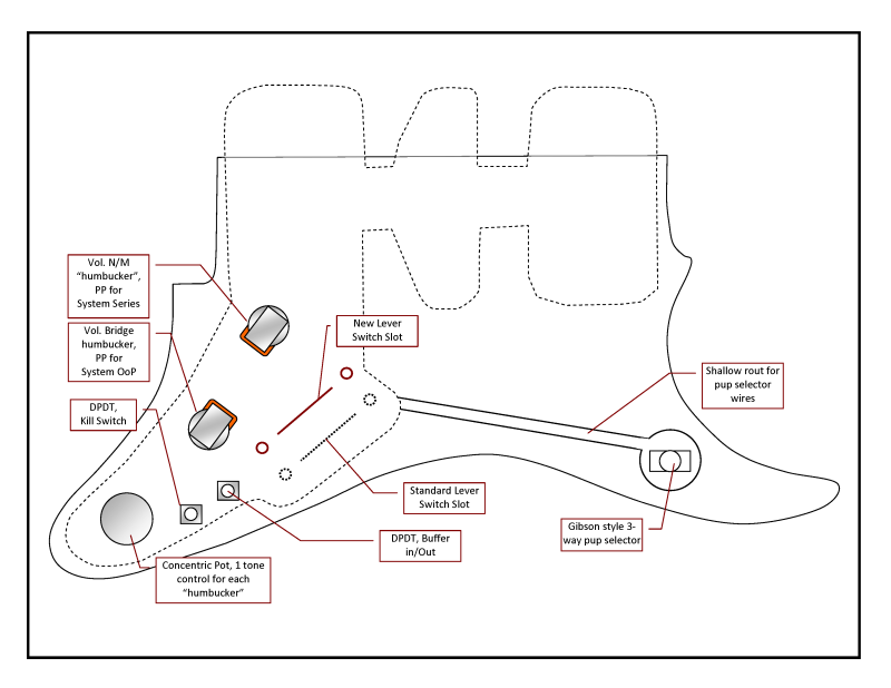
Year of Introduction: 2004 Mid and Neck (singles) "Humbucker" – “Real” Gibson P-90s. I will have to flip the magnet in the mid to get the RP part of RPRW. They are in the 7-8 Kohm range, I think www.gibson.com/en-us/Divisions/Gibson%20Gear/Pickups/P-90%20Single%20Coils/I bought these years ago from a guy who aspired to be a jazz guitarist but he never fully channeled his inner Joe Pass, so his new wife made him sell the …. Red Squire Affinity ... that he had a tech customize with two real gibby p90s. Those pups were the only reason I bought the thing. Paid like $80 then swapped the pickgaurd for a standard strat type with cheapo ceramics --- then sold that for a $100. Kept the Gibbies for this Midas project. switch type(s)By switch type do you mean the Mega Switch Ms or the thin body superswitches? Or other switches. If I can fit them I prefer the small bod supers --- if not, the thinner form factor Megas will have to do. I have sketched some placements but not actually to scale --- I am reasonably certain I will have to remove wood for the thin-body supers. However, I have wanted a lower horn located a Gibson style 3-way switch on a $trat for a while. Son-o had an odd semicircular lever switch in that positions on his venerable (and also odd) super-strat-derivative, mother-of-barstool Hofner from the 60s, and it was a blast. Still is. Really it was our first modding mule and we sort of tortured it back in the 80s.  All the nostalgia is to point out I will be hogging out some wood anyway for that switch location. I have some shorter switchcrafts, but the lower horn location does not have a lot of meat, so to save room I may have to go to one of the epoxy boxed type 3-ways. I always heard people dis those, but I never had probs with them …. However, I never play the same guitar twice. Once the woodworking tools are out, hogging out a little more for the lugged 5 ways would not be that big a deal. Other Switches- PP DPDT Volume for the N-M “humbucker” for System Series
- PP DPDT Volume for the Bridge “humbucker” for System OoP
- Short body Switchcraft or epoxy block 3-way Gibby style
Other Optional Switch(es)- Possible DPDT for an in-out of circuit buffer board
sort of scatological brain dump. RW |
|
|
|
Post by sumgai on Jun 4, 2012 18:53:56 GMT -5
From pÉƎᴚ⊥Çá´š
How the heck is that pronounced? Pee-a-za Sasshikas? Wow. It's pronounced "upside-down reTrEaD". View it with Text Encoding set to Unicode (UTF-8), it'll become obvious...  Still, I am starting to wonder.... Is 'TrEaD harboring secret Aussie fantasies?  HTH sumgai |
|
|
|
Post by reTrEaD on Jun 4, 2012 20:02:45 GMT -5
It's pronounced "upside-down reTrEaD". Or just say "Retread" while standing on your head.  Yes this goes in the direction I described earlier in making �automatic� preferred humcancelling selections. I am dense on understanding the �D buss� reference though. If you refer to John's original drawing there were 4 connections from the "local" sections to the "system" (top of the drawing) section. A, B, C, and D. The rest of that exchange about the hotter and colder sides placements gets away from me. We're just trying to reason out whether it will be less prone to hum if the HB is stacked on top of the P-90s or vice-versa, when in system series. Order of the Settings
I am still trying to understand the sound of the local Humbucker with cap bypass option. Is it a local series setting? Your description: "With the 5way, the Hb-cap bypassed, is a sound like a single coil, with added bass and a bit of a mid dip...." sounds like a local parallel sound with series Balzac...
It sounds different to the ear than local parallel? Is it a "hear-able" difference to the local parallel?
I ask because that affects the switching order of the 5 way. Yes, it is a local series connection of two coils with a cap across just one of them. I haven't done this myself. But I reckon it will sound very much like a single for high frequencies but with a thicker bottom end. No doubt John will be able to describe this better. Pickup types:
Bridge � Dimarzio Tone Zone P90� , P210
www.dimarzio.com/pickups/soap-bar/tone-zone-p90
Specs
Wiring: 4 Conductor
Magnet: Ceramic
Output mV: 385
DC Resistance: 16.77 Kohm
Year of Introduction: 2004
Mid and Neck (singles) "Humbucker" �
�Real� Gibson P-90s. I will have to flip the magnet in the mid to get the RP part of RPRW. They are in the 7-8 Kohm range, I think
www.gibson.com/en-us/Divisions/Gibson%20Gear/Pickups/P-90%20Single%20Coils/
I bought these years ago from a guy who aspired to be a jazz guitarist but he never fully channeled his inner Joe Pass, so his new wife made him sell the �. Red Squire Affinity ... that he had a tech customize with two real gibby p90s. Those pups were the only reason I bought the thing. Paid like $80 then swapped the pickgaurd for a standard strat type with cheapo ceramics --- then sold that for a $100. Kept the Gibbies for this Midas project. Okay, so the "HB" at the bridge is essentially uncovered. So IME, we'd be better off if the bridge pickup is at the bottom of the system series stack. switch type(s)
By switch type do you mean the Mega Switch Ms or the thin body superswitches? Or other switches.
If I can fit them I prefer the small bod supers --- if not, the thinner form factor Megas will have to do. You have 3 choices. The 2P4T tele four ways, the 4P5T Megaswitch M, or the 4P5T thin superswitches. The tele 4ways will require leaving coils "hanging from hot" but they can be made to work. The 4P5T switches are both a better choice, imho. If you prefer to work with lugs rather than pads, no problem. The wiring on either of the 4P5Ts is the same. So we'll figure on the thin superswitches for now. Other Switches
- PP DPDT Volume for the N-M �humbucker� for System Series
- PP DPDT Volume for the Bridge �humbucker� for System OoP
- Short body Switchcraft or epoxy block 3-way Gibby style
Other Optional Switch(es)
- Possible DPDT for an in-out of circuit buffer board
sort of scatological brain dump.
RW Most of that was already factored in, except the location of the DPDTs. If you do add a buffer, would the DPDT for that be a minitoggle, or a PP on one of the tone controls? |
|
|
|
Post by Runewalker on Jun 4, 2012 22:19:43 GMT -5
The wiring on either of the 4P5Ts is the same. So we'll figure on the thin superswitches for now. -RT definitely one of the 4P5Ts. I have to do some drafting on placement and fitment to decide on which type Mega M or SuperThin. If you do add a buffer, would the DPDT for that be a minitoggle, or a PP on one of the tone controls? -RT Rather than making two separate tone controls I will stay with the concentrics, then add a mini for the buffer. The buffer board would depend on my getting more aggressive with routing. |
|
|
|
Post by reTrEaD on Jun 5, 2012 6:04:37 GMT -5
Seems like everything is sorted, save for the order of settings.
Maybe John, Ash, and/or Newey can give you their opinion of the sound of series-with-one-coil-cap-bypassed, compared to single, series, and parallel?
|
|
|
|
Post by Runewalker on Jun 5, 2012 6:38:13 GMT -5
The design principle for the order of the Local "Humbucker" (quotation marks because of the split humbucker formed by the neck and mid singles) settings would generally go thickest to thinnest, top to bottom. Where this gets unclear (for me) is on the humbucker-with-cap-bypass and sort of arguable on the singles, depending on geographic orientation. I have never heard the humbucker-with-cap-bypass, but know the local-parallel sound very well. On my chassis with "hotter" (15-17 Kohms) humbuckers it turns a roaring over the top pup into a sweet PAF style puppy. If the local-series-humbucker-with-cap-bypass is "thinner" sounding, i.e., more "vintage-y", treble-y, and less powerful than the local-parallel then it would follow the local parallel. If it is thicker and more robust than local-parallel than it will precede it. Under the assumption that the local-series-humbucker-with-cap-bypass is more single coil-y than humbucker-y then the order would be: Lever Switch order - Neck/Mid "humbucker":1. (top lever Position) Local Series
2. Local Parallel
3. Local Series with-cap-bypass
4. "inner" single (Mid)
5. ("bottom" lever position) "outer" single (Neck) Lever Switch order - Bridge humbucker:1. (top lever Position) Local Series
2. Local Parallel
3. Local Series with-cap-bypass
4. "inner" single
5. ("bottom" lever position) "outer" single Inner pairs would be a RT suggests North and South polarities. Outer pairs would be a RT suggests North and South polarities. the other "auto" features RT described, which I vaguely understand, related to humbcancelling pairs when in OoP would also be built in. Thanks RW |
|
|
|
Post by JohnH on Jun 5, 2012 6:52:43 GMT -5
The cap-bypassed sound is made from a series-wired hb, with the cap across the neck-side coil. This allows the treble from the other coil to come through more clearly,as in a single coil, but with added bass from the bypassed coil. So I think of it as an alternative single coil sound, with more weight than a simple single. I think it has more edge than a parallel wiring. I prefer it to a bridge single cut from a bridge hb on my LP.
To go from bright to dark, I'd suggest single,single,hb-bypassed,parallel,hb
Cheers
John
|
|
|
|
Post by Runewalker on Jun 5, 2012 8:07:09 GMT -5
I think it has more edge than a parallel wiring. I prefer it to a bridge single cut from a bridge hb on my LP. ... I am all about "edge" To go from bright to dark, I'd suggest single,single,hb-bypassed,parallel,hb.
Then that supports the array I described above your last post. Thanks JH RW |
|
|
|
Post by ashcatlt on Jun 5, 2012 9:51:41 GMT -5
Theoretically and in practice I find the local parallel to be brighter than the SC settings.
The sound of the "broadbucker" kind of depends on the value of the cap it uses, but will definitely come between the SC and series sounds.
|
|
|
|
Post by reTrEaD on Jun 5, 2012 12:41:13 GMT -5
Comparing a single to two coils in parallel is highly subjective. Theoretically, since we have half the inductance, we would expect the tone to be "brighter". But in practice, other factors come into play. If the two coils aren't sensing the same location on the string, we have reinforcement and cancellation of various harmonics. Depending on which harmonics are missing and personal perception, the parallel pair might seem more bright to some and less bright to others.
I was somewhat surprised to see Runewalker put the "outer" singles at the bright end. In addition to the fact that the middle (an "inner") WILL sound more bright when used alone than the neck alone, I would expect the middle with the bridgemost single a little less close to the bridge would still sound brighter than the neck with the bridgemost single a little less close to the bridge. But again, I attribute that to personal perception.
Edit: I said part of that wrong. Corrections in red.
|
|
|
|
Post by Runewalker on Jun 5, 2012 13:43:13 GMT -5
Comparing a single to two coils in parallel is highly subjective. [/size][/quote] Agreed. I am very familiar with the local S/P jumbucker sounds and the brightness quality does shift depending on "hotness" and location. The broader sensing window to my ears often makes it a little warmer than the split coil, but as noted, there is subjectivity there. I was somewhat surprised to see Runewalker put the "outer" singles at the bright end. In addition to the fact that the middle (an "inner") WILL sound more bright when used alone than the neck alone, I would expect the middle with the bridgemost single would still sound brighter than the neck with the single a little less close to the bridge. But again, I attribute that to personal perception. [/size][/quote] Always a pleasure to offer "surprises." I should have noted the warm to bright design principle was not pure mandate. It should have been 1. warm to bright, top to bottom, except 2. positions 4 and 5, which would be inner then outer. # 2 is really a coin toss. Because of the HBD config I am just used to the inner/inner option being "default" and the Outer/Outer being sort of next in line. A player could get used to it either way. This reminds me of the weird Bill Lawrence designed Gibson L6-S rotary that more or less went from warm to bright, top arc to bottom arc. But it was not pure, as it mixed in some OoPs in the middle and end and that would make it in sequence not stay true to warm to bright. guitarnuts2.proboards.com/index.cgi?board=wiring&action=display&thread=5785Its array was: Gibson Super Humbuckering pups array in the L6-S
Six-Way Rotary Switch Selections
1. Both Pups System Series In-Phase
2. Neck Local Series
3. Both Pups System Parallel In-Phase
4. Both Pups System Parallel Out-of-Phase
5. Bridge Local Series
6. Both Pups System Series Out-of-Phase
for this double-barreled design, in positions 4 and 5, I was really thinking of the combos. In position 4 (next to bottom) the inner Humbucker split coil and Mid single would be brighter than the outer Humbucker split coil and Neck single, at least in Sys Parallel, and depending on the pups' individual volume mix. But you could argue it all kinds of ways. Yes on the humbucker splits, the mid inner would be brighter than the neck. However, I tend to use the Neck single more than the mid so a hard shove to 5th is less "fiddly" than finding the 4th position. On the Humbucker I tend not to use the split coil alone, and if I did I would prefer the inner position to roll off some of the ice pick. That decision of course conflicts with the "fiddly" precept. D@mn! nothings perfect. I also very much like the two forth positions in Series, gives the umph of a bridge humbucker with a smoothing of the intense brightness, and in parallel you can get some quack. can't talk smack if you ain't got quack .... Then finally the dual 5ths give a credible Tele sound and the mix can really shift the emphasis from jazzy with articulation, all the way to bitting with a growl (in Sys Series, vol up on the split and about mid point on the neck) So those notions were the other elements of my thinking, but I am not rigid on that. Thanks for helping me understand my own thinking. You don't always understand yourself until you have to explain it. RW |
|
|
|
Post by reTrEaD on Jun 5, 2012 15:25:29 GMT -5
Thanks for helping me understand my own thinking. You don't always understand yourself until you have to explain it. Amen. However, I tend to use the Neck single more than the mid so a hard shove to 5th is less "fiddly" than finding the 4th position. Nuff said. This alone is a strong enough reason for breaking a pattern you may have set. can't talk smack if you ain't got quack .... Hell yeah. |
|
|
|
Post by Runewalker on Jun 8, 2012 11:57:23 GMT -5
Further questions have ferreted out some details needed to complete the wiring diagram. With his permission I have quoted pÉƎᴚ⊥Çá´š's inquiries, then included my responses. Getting back to the wiring...“I think we've defined the electrical parameters. About the only thing left is for John to decide whether the bridge side or the neck/middle should be raised in the system series mode. I'll leave that decision to John. He knows my concerns about the unused bridge coil "hanging" from the middle of the series string. But P-90s are more susceptible to hum and noise. The coils are mostly above the body. So cavity shielding is less helpful. Whatever John decides on which trumps the other will be fine by me.” John H, do you have a flag to plant in the ground on: "whether the bridge side or the neck/middle should be raised in the system series mode."? You are right about the P90 penchant for hum. The gold strat-P90ified had some hum problems inspite of shielding efforts. On the re-build I will probably engage the group on solving some of those probs. I think I noted previously I had even copper foiled the inner sides of the P90 plastic covers, tying them into the cavity shielding, of course.... but it never quite killed the 60cycle buzz. If I would just grow up and not satuate the gain it would not be as big a prob, but not growing up is the point of these excursion and rockin' out. “We can move forward with the thread if you make a drawing of where the controls are located, in relation to each other. I think if you grab a PDF from fender for a strat, you could do a "print screen" copy of the front of the pickguard. Paste that into a drawing and edit in the necessary stuff….Even something as simple as a line on the drawing will suffice “ Yeah I have all of that and can do the drawings. I will try to sneek some time at btw too much responsibilities --- at least for the important stuff ---like designs and builds and most of all playing. II’ll fix you up with something better than a “line drawing.” But I am totally good with translating handdrawn notes or mark ups into a rendering. I’ll set up components and locations. “We know the two superswitches will be parallel to each other. Probably in the same axis as the standard location. But which one is for the neck/middle and which is for the bridge?” I am experimenting with placement. Final determination won’t slow the wiring diagram development, as relative placements will be fine for that purpose. Yes they will be parallel in the same axis. I am leaning toward some routing and changing the angle of the slant. But the basic array will select the 5-way closest to the neck as the control for the neck and the other one will control the bridge. Just straightforward visual logic. The location and lever axis of the Gibby toggle needs to be defined. Like the mother of barstool Hofner pix posted earlier, I’ve always wanted a gibby threeway on a strat --- on or close to the lower horn So I probably will rout a shallow channel for wires and a deeper hole for the 3-way by the horn. Unless I change my mind and just go with a paddle handled mini 3-way to minimize routing. “your stacked tone pot was a single shaft (dual gang) or concentric (two stacked knobs or knob and ring). If it's a single knob, nothing more needs to be decided. But if it's concentric, we need to know if the inner shaft (top knob) is for the bridge or for the neck/middle.” Concentric. I have always set them up so the smaller knob, controls the neck and the larger bottom knob controls the bridge. I will have to check on the inner versus outer shaft and its orientation to the top or bottom pot. Good question. Hope that gets those questions addressed. I'll try to promp JH on the question you asked. Thanks! RW |
|
|
|
Post by JohnH on Jun 8, 2012 16:37:50 GMT -5
OK, I just read through it all again, and checked out the intended pickups, in order to think further about the question of series wiring noted above: Bridge: DiMarzio Tone Zone P90 humbucker So, it has a plastic cover, and therefore unshielded as noted before. But 4 conductors, in a seperate braided shield. also, both coils look similar, so each should work as a single coil, but may both sound similar except one is a bit nearer the bridge. Neck and Middle: Gibson P90 Traditional, plastic covred single coil, with braided wire. And that leads to another issue. The braid of the Gibsons is both signal ground and baseplate/shield ground, leading to further factors to consider with phase changing and series placement. RW, would you be up for changing the wiring of the two Gibbos to two seperate conductors plus braid, if this was deemed desirable? Microphone cable with 2 cores is ideal for this. You could do this at the same time as opening up to reverse magnet phase, which will need rewiring of some kind anyway. John |
|
|
|
Post by Runewalker on Jun 9, 2012 0:07:04 GMT -5
JHboth coils look similar, so each should work as a single coil, but may both sound similar except one is a bit nearer the bridge. Yes, they will be nearly indistinguishable as singles, but it is the primary humbucker (Tonezone) I was after and the combos with the neck and mid. I have a vicious Schecter Avenger with a ToneZone and I find it a remarkable pup, rancorous in full bore, but cleans up nicely. like this but black: static.musiciansfriend.com/derivates/18/001/593/539/DV016_Jpg_Large_H68258.001_black_cherry.jpgSo when I found it in the p90 form factor I knew it was bound for this application. Traditional, plastic covred single coil, with braided wire.
And that leads to another issue. The braid of the Gibsons is both signal ground and baseplate/shield ground, leading to further factors to consider with phase changing and series placement.
RW, would you be up for changing the wiring of the two Gibbos to two seperate conductors plus braid, if this was deemed desirable? Sure. There is nothing about this project that was ever easy. It started with trying to adapt a strat pickgaurd to those huge singles, to the incompatible mounting required in that thin 1/4 inch of wood between pup and spring cavity routings --- no springs-on-pickgaurd approach is possible --- no brackets on the pups --- no room in the little bit of plastic left on the neck pup. I actually had to put bushing inserts for machine screws that go through the P90. So the beast simply flogs me every chance it gets. What's a few more lashes?
|
|
|
|
Post by JohnH on Jun 9, 2012 1:41:20 GMT -5
Well then, based on everything known so far, here is my thoughts on this wiring. - 5 way switches, with combo selections as noted by RW
- Retreads clever trick with the phase switch, on the bridge pup
- Put the bridge pup on the ground side of the series chain
- Rewire the N and M Gibson pups with two-core mic cable, with separate ground for the braid, which also grounds the pickup back plates
- If possible, foil the inside of the N and M plastic covers, and ground the foil
- Do whatever magnet flipage is required to make N and M different polarity (reversing the wire connections to maintain phase)
- Arrange the B, M and N coils physically so magnetic polarity alternates with adjacent coils being opposite, so both 'inner' and 'outer' coils are different polarity
That orta do it! cheers John |
|
|
|
Post by reTrEaD on Jun 9, 2012 11:10:54 GMT -5
Yep, pretty much. Add to that a front panel map of the relative locations of the switches and the directions they move. Could get a bit gnarly keeping track of "who's on first". The DiMarizo at the bridge will be the easiest, but even that will be slightly ambiguous. We can define which polarity (north or south) is closest to the bridge, but identifying it by external looks isn't as simple as "slugs or screws" since both sets of polepieces are screws. The Gibsons have even more potential for losing track. I don't know if they are normally south up, or north up. And since one of the magnets will be flipped, the coil connections will be reversed when the signals are in-phase, hum-canceling. This could be done at the connection of the cable to the coil. Or it could be done by using opposite colors when the cable is connected to the circuit. Either would work. Long story short, I predict a good bit of time will be spent checking magnetic polarity and with the "screwdriver test" for output polarity. Good notes will be the key to getting the wiring right the first time. |
|
|
|
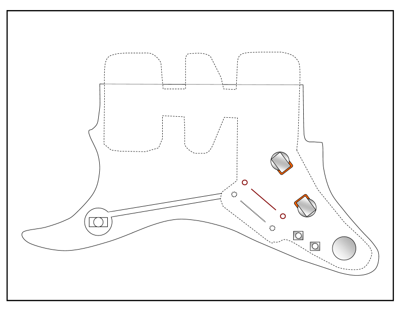
Post by reTrEaD on Jun 9, 2012 12:27:35 GMT -5
This is worthy of a separate post. 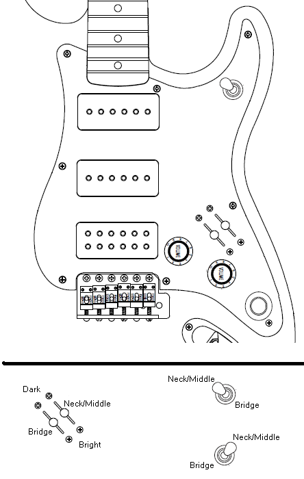 I think I have things laid out in approximately the right relationships. But I'm not sure about the orientation of the Gibson toggle. There are two possibilities in the lower right. But not shown are with the movement going north to south or east to west. Once we establish toggle orientation and confirm rest of the layout, I think a link to the toggle you're using would be the last requirement from you, before we lay out the drawing components (minus wiring) for the wiring diagram. |
|
|
|
Post by 4real on Jun 9, 2012 14:38:54 GMT -5
Interesting guitar... on the subject of toggle orientation, I really like gibson style toggles...  I used one in the old test guitar that ended up with the first sustainer but included all kinds of stuff like this. In both this and subsequent guitars, my telecaster and my LP that can be seen in the gallery, I orient the switch up and towards the neck for the neck pickup and down and 'back' for the bridge. To me it seems to make visual sense and be easy to switch but harder to 'knock' out of position. There can also be space reasons, particularly on my telecaster that would not have worked without such a 'tilt' to it. I can confirm also that the selector also seems to be more 'ergonomic' too in this orientation changing with a hand sweep over pushing away or pulling it towards you. The intention on this guitar (though most of my guitars use such switches since this one built many years back) was to have three selections the character could be set by the three phase switches and the middle control which was a volume control on the middle pickup. An interesting thing, at least on this guitar was, that the middle pickup out of phase reversed the usual 'stratty' OoP kind of sound in combination giving a kind of mid-range boost rather than cancellation which wired out of phase. The result is the middle control could dial in either the stratty sound or a more HB like sound...so a useful 'tone' control. It was also not effected by the master tone control as I recall. The toggle on mine simply selected the bridge or neck to which you could dial in the middle and preset the phase switches (of course, one is kind of redundant, but it did give a good visual reference of which pickup was set where) It looks like a cool looking setup that similarly should be visually obvious as to what 'mode' the selections are in. Be sure to measure the gibson toggle so that the cavity will fit under the scratchplate where you intend to put it on that lower horn. Some toggles such as a legit low profile gibson can be quite large! |
|
|
|
Post by Runewalker on Jun 9, 2012 22:06:34 GMT -5
This is worthy of a separate post. We'll work on that. I think I have things laid out in approximately the right relationships. But I'm not sure about the orientation of the Gibson toggle. There are two possibilities in the lower right. But not shown are with the movement going north to south or east to west. Beautiful and clear rendering. I will include the one below I was working on, but yours is clearer. I like the notion of orienting the 3 way E-W i.e., movement in the direction of the neck for selecting the neck pup, in the direction of the bridge pu for selecting the neck pup. However, I played Les Pauls for years and the motor memory is still --- up for neck and down for bridge. I think also while playing, that up and down is more like picking directions than back and forth. So I will stick with North - South. Here are the layouts I was working on: - Pickgaurd face.
- From the back of the pickgaurd
- Components from the back of the pickgaurd.
   |
|
|
|
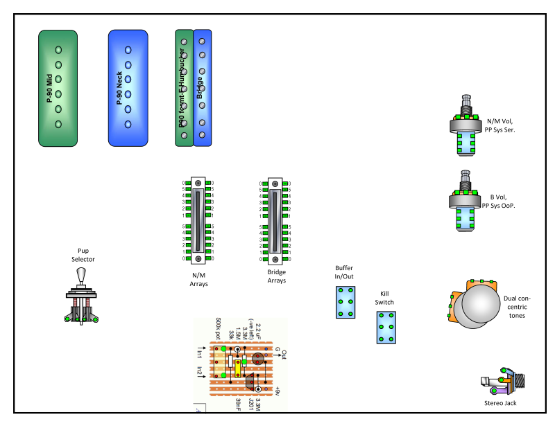
Post by JohnH on Jun 9, 2012 22:46:16 GMT -5
Very nice renderings both chaps.
RW, 'tis a joy to see your artistry with Word-shapes again. On the last diag, if pickup colours relate to polarity, you should reverse the colours on either the bridge pup, or the N/M pups, to make it possible to find in-phase combos of inner and outer pairs.
If you use a buffer, it takes three poles if you really want it bypassed and switched off. But I would suggest not making the on/off switch the same as the bypass, to avoid switching transients - just use a stereo jack, like a stomp box. The buffers use so little power than leaving it on while you are plugged in is not an issue. In this case, a two-pole switch as you have it is fine.
so Retread, will you be adding the wiring to the diagram? If you wish to, please do! or I'll have a go if you prefer.
John
|
|
|
|
Post by 4real on Jun 9, 2012 23:03:15 GMT -5
Fair enough, me too. as you can see on my tele, it is just a subtle twist. my LP and load strat is similar..but a small point. Great work on the diagrams... 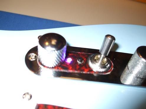 |
|