sonosonny
Apprentice Shielder

Posts: 33
Likes: 0
|
Post by sonosonny on Jun 12, 2012 14:02:48 GMT -5
RT
Yeah I talked with Rune this a.m. per reasons why the topic was not in the Nutzoid zone..... and now realize that finished projects only make it to the TNS area.
Looks like this one is getting closer with each day.
I am sure I will play a major role in wiring this up with Rune, so will stay tuned for further developments and begin heating up the iron.
Son-O
|
|
|
|
Post by reTrEaD on Jun 13, 2012 15:27:26 GMT -5
Yeah Son-O, this has already moved forward a great deal. But since it's a complicated endeavor there will be challenges to be met, every step of the way. We're already on the fifth page and I predict several more before the dust settles. It makes for a good read, if one has the patience to wade through it.
|
|
|
|
Post by sumgai on Jun 13, 2012 17:34:08 GMT -5
.... if one has the patience to wade through it. I see where Cabela's has a nice sale on all styles of waders right now.....  |
|
|
|
Post by JohnH on Jun 14, 2012 7:59:51 GMT -5
Here is a diagram update:  Buffer not in yet. the switches are so that pushing them down and towards bridge will engage series sounds. When selecting n or m singly, n,being outer, is then nearer the n pup. But the wiring of each could be spun 180 degress if wanted. The correct DiMarzio pickup wire colours are not determined, but so far black is cold and grey is hot. I'm not sure the placements are right. The n/m switch is nearer n and m, but is lower than the b switch, while the pot for it is higher,as on an LP. John |
|
|
|
Post by reTrEaD on Jun 14, 2012 11:40:12 GMT -5
Hi John, I kinda dropped the ball on the mapping. Most of what you weren't sure about could have been defined before you drew the wiring. We should get feedback from Rune to confirm, I think the placement of the switches are right, but the sequence is reversed. Also, I think the tone pots are swapped and the killswitch works backward. To be consistent with the numbering next to the switches, the sequence should be as follows: 5 - Neck (Bridgemost) 4 - Middle (Almost Bridge) 3 - Parallel 2 - Series (with cap bypass) 1 - Series Below is an updated map of the front panel, AND a flipped rotated view (as if looking at the back of the pickguard). I've noted the position of the switch terminals on the right of the last image. 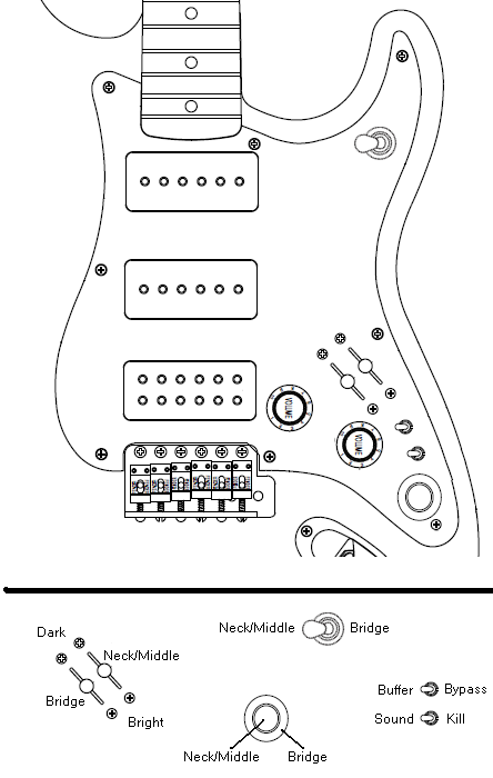 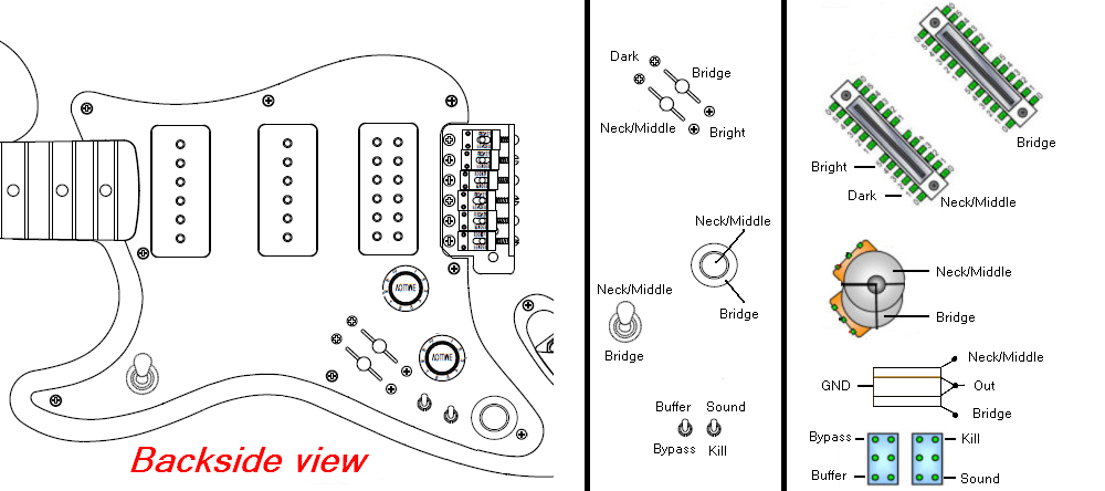 |
|
|
|
Post by JohnH on Jun 14, 2012 15:37:04 GMT -5
Im aware that the switching order is reversed compared to RWs list. Just being contrary! I would actually suggest it to be as I have drawn, if it was for me, so the N and M selections are in a logical order, but its RWs call.
The Word graphics are a vector program and the wires can all be spun around in a minute with no problem.
I have not seen RWs view on tone pot or kill switch direction, but again its easy to change.
J
|
|
|
|
Post by Runewalker on Jun 14, 2012 16:37:18 GMT -5
RT[ color=Purple]"We should get feedback from Rune to confirm,..." [/color][/blockquote] Uh..Oh. bolded. Getting close to ALL CAPS! "I think the placement of the switches are right, but the sequence is reversed…" JH
"...When selecting n or m singly, n,being outer, is then nearer the n pup. But the wiring of each could be spun 180 degress if wanted...."
Uh … John, I am not quite sure you are saying the order is like: Here is what I meant, looking from the back of the pickgaurd: 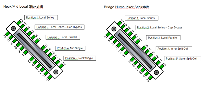 On RT’s pix of the parallel Local “Stick-Shifters” the end labled “Dark” is the Neck/Mid Local Series and the Bridge Local Series, or the # 1 position on the pix above. And the Lables RT has on the N/M Shifter and the Bridge Shifter are correct. RT, basically everything you note on your map is correct. JHThe correct DiMarzio pickup wire colours are not determined, but so far black is cold and grey is hot. Here is the correspondence from Dimario Tech on the P90 TZ: That is correct.
(see below for the question/statement)
-----Original Message-----
Posted At: Monday, June 11, 2012 7:51 AM
Posted To: Tech
Subject: The Tone Zone P90™ DP210 Question
I have the subject line pup. I am installing in a custom wiring configuration and am at the point where I need some additional tech specs.
The following is the standard reference I have for Dimarzio humbuckers:
Screw Pole coil - South
Start – Green [/b][/color] Finish – WhiteSlug Pole Coil Start – RedFinish – BlackHowever, since both coils have adjustable coils can I assume: • that the one with Green and White wires is indeed the South coil; • and the one with the Red and Black wires is the North coil? Thanks[/blockquote] Also RT had a question earlier about the Dimarzio North/South color coding: 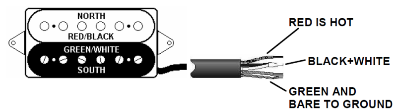 I started capturing John's adjustments on my drawing file then realized after this discussion that the Local StickShifter order may be reversed on his drawing. So I will wait until that is clarified. Thanks RW
|
|
|
|
Post by reTrEaD on Jun 14, 2012 20:38:51 GMT -5
Uh..Oh. bolded. Getting close to ALL CAPS! Yeah, I'm bold like that. The Word graphics are a vector program and the wires can all be spun around in a minute with no problem. John, is that a free program or does it cost munnies? |
|
|
|
Post by Runewalker on Jun 14, 2012 21:11:04 GMT -5
The Word graphics are a vector program and the wires can all be spun around in a minute with no problem.
John, is that a free program or does it cost munnies? All Billy Gates progs cost too much. My solution? have a kid and get the student discounted version of Office. It comes as a standard suite from work. Otherwise I would use something else. But the drawing features are better than expected on the Office suite. |
|
|
|
Post by yakkmeister on Jun 15, 2012 0:36:23 GMT -5
I'll jump in here with computer advice. Office is too expensive:Yes. Try thisIt's called Libre Office. It's FOSS (Free, Open Source Software). That means it costs no munnies. Vector graphics programs have kidnapped my babies!Um ... call the police? But seriously, there are several very good programs for doing all things graphical in the FOSS paradigm. Circuit diagrams are also catered for here and here. Although I don't use either of those. |
|
|
|
Post by Runewalker on Jun 15, 2012 5:50:34 GMT -5
I'll jump in here with computer advice. Office is too expensive:Yes. Try thisIt's called Libre Office. It's FOSS (Free, Open Source Software). That means it costs no munnies. Vector graphics programs have kidnapped my babies!Um ... call the police? But seriously, there are several very good programs for doing all things graphical in the FOSS paradigm. Circuit diagrams are also catered for here and here. Although I don't use either of those. Thank you YakM. Useful links. I will try those. I have tried Open Office and for basic word processing it is fine. It's drawing features are limited within it Writer program, especially the capability to manage Line points. I have used it in sharing files with JH for years because mainly we both have it and are both very familiar with it. Which is not an endorsement, just that it was a common vehicle. Billy G has enough "munnies" and probably munys as well. Hard to beat free. |
|
|
|
Post by yakkmeister on Jun 15, 2012 6:49:28 GMT -5
I'll jump in here with computer advice. Office is too expensive:Yes. Try thisIt's called Libre Office. It's FOSS (Free, Open Source Software). That means it costs no munnies. Vector graphics programs have kidnapped my babies!Um ... call the police? But seriously, there are several very good programs for doing all things graphical in the FOSS paradigm. Circuit diagrams are also catered for here and here. Although I don't use either of those. Thank you YakM. Useful links. I will try those. I have tried Open Office and for basic word processing it is fine. It's drawing features are limited within it Writer program, especially the capability to manage Line points. I have used it in sharing files with JH for years because mainly we both have it and are both very familiar with it. Which is not an endorsement, just that it was a common vehicle. Billy G has enough "munnies" and probably munys as well. Hard to beat free. No probs. A lot has been done with LibreOffice to smarten up the graphics processing but I admit I never use it for that. I use Inkscape for vectors and GIMP for rasters. I use these for any and all graphic design work that I do. I don't use scribus, but it's very good. I just never needed to make a magazine. When it comes to writing documents, if my university wasn't a bunch of techno-noobs with no ability to adapt to better technologies ... I would be using LyX for all my 'word processing' needs. Holy sh@&bags, batman! it's the best! goodbye spending ages on pagination, re-numbering stuff or organizing references, footnotes etc ... and it's a technology that's been around in various forms since 1978 (TeX, LaTeX, MiKTeX). But ... that's derailing now ... back to you regularly scheduled forum! |
|
|
|
Post by JohnH on Jun 15, 2012 7:51:26 GMT -5
OK, the wiring diagram is all done...  Be carefull with those series connections. John EDIT: I managed to simplify the diagram....  Yes its a lot of wires, and needs some untangling no doubt, but at least it's easier to build than the London Underground!. And you are getting 111 different sound settings (who can find the 111th?). The switches, I think, are as you intend but retread could check. I also substituted a picture of one of the buffers that you have assuming it's to be one of those. cheers John Edit - pup labels fixed per comments below |
|
|
|
Post by reTrEaD on Jun 15, 2012 9:31:12 GMT -5
OK, the wiring diagram is all done... *map* lol And you are getting 111 different sound settings (who can find the 111th?). Would that be the sound of the guitarist saying " hot damn!" ? I'll invest some time proofreading, although it probably won't need it. I see you've added a black wire to system ground for the black wires related to the 'automatic coil swapping' function. I had neglected to point that out on the last iteration. ETA: I checked the 5-ways (nothing else). The sequence looks correct according to the position of the P-90s in the drawing. But the labeling doesn't match their position on the drawing. |
|
|
|
Post by JohnH on Jun 15, 2012 16:21:21 GMT -5
ETA: I checked the 5-ways (nothing else). The sequence looks correct according to the position of the P-90s in the drawing. But the labeling doesn't match their position on the drawing. OK thanks. Do you mean the 0 1 2 3 4 5 labels? I don't usually look at those. One feature to consider is the use of treble bleed with the buffer. at full volume they make no difference, whether or not the buffer is engaged. At lower volume, with buffer engaged and no treble bleed, the tone would be identical to full buffer volume. But with TB in circuit plus buffer, it will transition to a tone more like the full-vol unbuffered version as volume is turned down. All good tones either way. Maybe use the TB, but with a slighty smaller cap, say 0.82nF instead of 1nF, plus 150k resistors J |
|
|
|
Post by reTrEaD on Jun 15, 2012 16:40:09 GMT -5
Good question about the treble bleed. Maybe undercompensating might be a good compromise. With the buffer, the TB comp will add more treble that shouldn't be there, when the volume is rolled down.
I can see an easy fix for this by incorporating the TB with the bypass switch. But that would only work for a single volume control design. It wouldn't fit here.
I didn't mean the 0 1 2 3 4 5 labels. I meant the labels on the image representation of the two P-90s. The one farthest to the left is labeled "P-90 Mid".
|
|
|
|
Post by JohnH on Jun 15, 2012 17:04:10 GMT -5
Ok thanks, I have fixed that on the previous post for RW.
I think there will also be an advantage in considering the routing and arangement of grounding wires - mainly for ease of wiring, but RW can work that out. Also, grounding of braids to pickup bases, ground wire for bridge/saddle, and possible grounded shielding inside P90's as noted before.
J
|
|
|
|
Post by reTrEaD on Jun 15, 2012 17:56:20 GMT -5
I agree that RW is really the best one to work out the final arrangement. And there are still a few undefined minor details, like color codes for the P-90s after he recables them. Also RT had a question earlier about the Dimarzio North/South color coding: I already knew the standard for North vs South regarding Dimarzio. Although they did have at least one oddball (the DP163 Bluesbuckerâ„¢) that doesn't follow that pattern, everything else I have seen from them does. So confirming that was important. I'm still curious. Can you see which coil the wires go to, from the outside? Or will you have to take the pickup apart? |
|
|
|
Post by Runewalker on Jun 15, 2012 21:57:16 GMT -5
RT "I agree that RW is really the best one to work out the final arrangement. And there are still a few undefined minor details, like color codes for the P-90s after he recables them."
I will need a little review on this converting the p90s from braid and single wire to two wire with braid surround. But as you note it has not been done so the color code is not established. For the purposes of the diagram we may need to just designate start and finish with arbitrary colors. (on the Dimarzio P90 TZ) I'm still curious. Can you see which coil the wires go to, from the outside? Or will you have to take the pickup apart? You can't see from the outside. There are screws holding the back plate to the coils, but I have not ventured in to breaking it down. |
|
|
|
Post by reTrEaD on Jun 15, 2012 23:48:57 GMT -5
You can't see from the outside. There are screws holding the back plate to the coils, but I have not ventured in to breaking it down. You won't need to open it up unless you really want to. We can learn all we need to, from the outside. Magnetic compass, meter, and screwdriver. Oh and a notepad and pencil. I will need a little review on this converting the p90s from braid and single wire to two wire with braid surround. But as you note it has not been done so the color code is not established. For the purposes of the diagram we may need to just designate start and finish with arbitrary colors. This is where the conversation will get tricky. Could take several posts to get everything just right. Important things to remember: "start" to "finish" with a given magnet polarity could give us a different output than we expect. It depends on the winding direction. Standard convention: South Up magnet (attracts north needle of compass) Clockwise wind Start is ground finish is hot = standard output phase = signal goes positive as string approaches polepiece, signal goes negative as string moves away from polepiece. I'm fairly certain Dimarzio winds their HBs Clockwise. The start (green) of the South coil is ground (-) and the finish (white) of the south coil is hot (+). This is the same convention as a modern standard strat single coil. The North coil is also wound clockwise. But we reverse the way the connections are made. The start (red) of the north coil is hot or (+) and the finish (black) is ground (-). Confused yet? The Gibson P-90s are anybody's guess. I don't know what direction they are wound or what magnetic polarity they are. And I don't know if the start is hot or ground. But if you check magnetic direction with a compass and do the screwdriver test we can know most of what we need to before you open them up. It's entirely possible we can keep good enough notes that you could use red and black on the north up p-90 and white and green wires on the south up p-90. |
|
|
|
Post by JohnH on Jun 16, 2012 18:33:32 GMT -5
How about this simplified method? – I think it will work and cuts past a few issues with winding direction, start/finish etc:
Place the Bridge Hb to best suit its position. With two equal screw coils, this may come down to deciding which end is most convenient for the wires to come out of.
Identify the wire colours for each bridge coil as placed, using tap tests, so that inner and outer wires are known and wired per the diagram
Open up the two P90s. Flip one magnet. Wire with dual braided core. On the one that got mag-flipped, swap the wire colours to the coil.
Eg. For the non-flipped one, the internal coil wire (start or finish, but don’t worry) that was originally going to the braid is wired to black, and the other coil wire to white. The new outer braid goes to baseplate and to any shielding that gets added.
On the mag-flipped p90, do as above, but reverse the new white and black colours so white goes to the wire that was originally grounded.
Place the P90s, so that to get alternating North and South coils, relative to the bridge (ie, adjacent coils attract if placed face to face). Doesn’t matter which is really N or S, just that adjacent coils are always different.
That will solve the coil mods and pup placement. The only variable left is whether the new P90 black wires both go to their respective hots, or they both go to colds. This can be determined by a screwdriver pull-off test.
cheers
John
|
|
|
|
Post by reTrEaD on Jun 16, 2012 22:33:08 GMT -5
John, your simplified plan sounds reasonable. But I think getting some information on the original magnet polarity, winding direction, and which end (start or finish) is hot, would be useful. It will be easy to take a few notes before the changes are made. Regarding magnet polarity, I think the North-South axis is inside to outside rather than top to bottom. Flipping the magnets top to bottom will move the inside to the outside, if the magnets are NOT rotated end to end. Or the magnets could each be rotated end for end if the magnets are NOT flipped. Either will change the polarity. Both will accomplish a double-reverse. 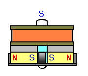 In any case, marking the magnets before removal would be wise. |
|
|
|
Post by Runewalker on Jun 18, 2012 17:19:45 GMT -5
Sorry about the delay gents. Been doing work and family duty…. I pulled out the meter and took some readings: P90s- P90 1: 8.13K ohms, screwdriver pull-off test moves needle to the left
- P90 2: 7.90K ohms, screwdriver pull-off test moves needle to the left
Dimarzio P90 form-factor Tone Zone:- Coil 1, Red and Black wires: 8.73, screwdriver pull-off test moves needle to the left.
- Coil 2, White and Green wires: 7.82, screwdriver pull-off test moves needle to the right.
Still not sure on the cardinal directions questions, but know a little more now about which coil is which on the Dimarzio. Drawing of that pup follows the pix below. Here a pix on the Tone Zone opened up. 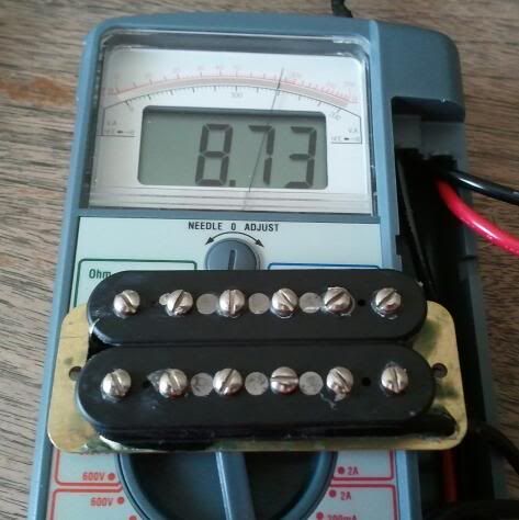 Here is a pix of the p90 showing the magnets from one end. 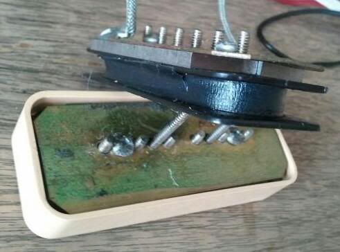 Looking at the graphic below, which way should the magnets be flipped on one of the P90s: A. or B.? Looking at the graphic below, which way should the magnets be flipped on one of the P90s: A. or B.?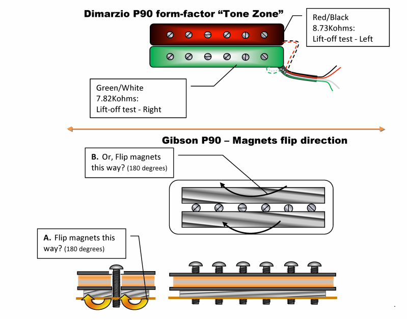 |
|
|
|
Post by reTrEaD on Jun 18, 2012 22:22:39 GMT -5
I pulled out the meter and took some readings: P90s- P90 1: 8.13K ohms, screwdriver pull-off test moves needle to the left
- P90 2: 7.90K ohms, screwdriver pull-off test moves needle to the left
Normally we use voltage measurements for the pull-off test. But I suppose we could use resistance. It's important to note which connection goes to the red lead of the meter. Center or shield? Dimarzio P90 form-factor Tone Zone:- Coil 1, Red and Black wires: 8.73, screwdriver pull-off test moves needle to the left.
- Coil 2, White and Green wires: 7.82, screwdriver pull-off test moves needle to the right.
These should have the needle moving in the same direction. But since you don't indicate which wire is being connected to the red of the meter, it might be because of reversed connections. Looking at the graphic below, which way should the magnets be flipped on one of the P90s: A. or B.? If you flip like "B" it will change the polarity if I'm right about the axis, but not if I'm wrong about the axis. If you flip like "A" it will change polarity whether I'm right or wrong about the axis. So flip like "A". |
|
|
|
Post by Runewalker on Jun 19, 2012 5:55:07 GMT -5
RT:Normally we use voltage measurements for the pull-off test. But I suppose we could use resistance. It's important to note which connection goes to the red lead of the meter. Center or shield? It has been a long time since I conducted the "screwdriver pull-off" test, so I did it the way I remember. But I want to give you precisely the info you need, and will re-run it. - For the voltage approach which setting do I select on the multimeter?
- I will be sure to note black and red probe connections. Do you want the Green/White and Red/Black associated with specific probe colors? For
example, do you want Green to Red and White to Black, or the reverse?
So flip like "A". A it is. It was interesting to me that the two coils of the Dimarzio had such a large variance in dc resistance readings. I have measured a lot of humbucker coils and while I typically see minor variances I have never seen humbucker coils with this much of a spread between them.
|
|
|
|
Post by reTrEaD on Jun 19, 2012 6:04:22 GMT -5
DC volts, lowest scale available.
I would expect pickup White to meter Red and pickup Green to meter Black will give you the same needle deflection as Red to Red and Black to Black. And I expect those will both match the P-90s with core to meter Red and braid to meter Black.
Any chance you have a compass and can check magnetic polarity of the P-90s?
|
|
|
|
Post by Runewalker on Jun 19, 2012 6:41:10 GMT -5
DC volts, lowest scale available. I would expect pickup White to meter Red and pickup Green to meter Black will give you the same needle deflection as Red to Red and Black to Black. And I expect those will both match the P-90s with core to meter Red and braid to meter Black. Any chance you have a compass and can check magnetic polarity of the P-90s? I'll work on the meter test after work tonight. Compass. My boy scout days are so far behind me ... and in so many ways. So no, I don't have a compass... but I thing Son-O does .... so let me try to secure that "testing device." Thanks RT. |
|