|
|
Post by newey on Jun 1, 2012 22:11:18 GMT -5
Here's a schematic for a simple, straightforward scheme useable with any guitar with 2 single coil pickups and room for a 5-way Superswitch™. There's nothing particularly earth-shattering here, and it's probably not an original idea (although I don't recall seeing it exactly before) This could be done on a Tele if one uses the new "narrow Superswitch". This is meant to keep things simple for stage use. The Superswitch is the only switching used. It makes 5 useable sounds from 2 SCs, including a series OOP setting. The SOOP setting is wired in the #3 position, since a quick flick of the 5-way is not likely to end with the lever in the middle. One must more-or-less purposely put the guitar into the OOP mode, it's less likely to end there accidentally than if the OOP was at either end of the switch, or at positions 2 or 4. Since I was only using 3 poles of the SS, the 4th pole was drafted to switch tone capacitors, allowing a different tone cap for positions 1 and 2 (neck alone and neck + Bridge) and for 4 and 5 (Neck * Bridge and Bridge alone). For position 3, the SOOP position, no cap is connected and the tone pot is out of the circuit; this should give a bit more output and brightness in the OOP setting. Of course, either of the caps could be connected there if one wants to have the tone control operable on the OOP setting.  This hasn't been built yet, nor has the schematic been vetted, but it should be OK. I may get around to building this in the future if I ever get that Duo-Sonic I've been eyeballin' . . . But I think it's a good scheme for the most useable sounds all on one switch, no push/pulls or other foofaraws. I'll work on a wiring diagram for this in the near future. |
|
|
|
Post by yakkmeister on Jun 2, 2012 1:53:06 GMT -5
I am thinking I should have a look at implementing this ... Just need another guitar ...  |
|
|
|
Post by newey on Jun 3, 2012 9:09:48 GMT -5
And here's a wiring diagram. It should be all OK although I'm always leery of how the pots are shown as far as the CW and CCW lugs go. I've shown them "upside down", as if one were wiring them, and I think I've got the lugs right as shown in that position- If I've reversed them please let me know and I'll swap it around. Values for C1 and C2 are "flavor to taste" . . . Also, note that the Bridge pickup is designated as "position 1", neck is #5 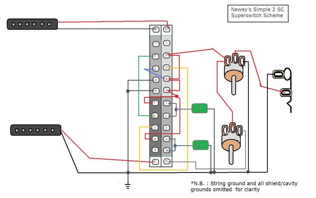 |
|
|
|
Post by ChristoMephisto on Jun 3, 2012 9:52:46 GMT -5
Nice layout and switching arrangement, reminds me of the T-Riffic wiring.
Looking at the last diagram, if you replace the blue wire with a 0.01 cap, it'll give you a low cut/hi pass for the out of phase neck pup.
Same thing you find in the 'half out of phase' wiring
|
|
|
|
Post by newey on Jun 3, 2012 21:13:04 GMT -5
Good idea, CM! I had thought of HOOP, but had sort of put it out of my mind by the time I got to the OOP setting. But a simple cap would do it, replacing the blue wire at position #3. We'll call that version the "CM mod".  |
|
|
|
Post by ChristoMephisto on Jun 4, 2012 10:07:08 GMT -5
If you want to call it the CM mod, it'd be cool with me  just reviving and old idea |
|
|
|
Post by enquirydave on Feb 28, 2013 19:02:10 GMT -5
Hi
Is there any chance of showing the diagram for two pickups (humbuckers) with the following arrangement:-
( + = Parallel and x = Series)
1) Neck
2) Neck + Bridge
3) Neck x Bridge (Series Out of Phase)
4) Neck x Bridge
5) Bridge
as I have tried adapting your diagram and have the following order!
1) Neck
2 Neck x Bridge
3) Neck x Bridge (Series Out of Phase)
4) Neck + Bridge
5) Bridge
which is basically positions 2 and 4 reversed.
I cannot turn my superswitch around in the cavity as it only fits in one direction.
Please can you help?
David
|
|
|
|
Post by newey on Mar 1, 2013 6:08:14 GMT -5
?dave:
That can easily be done. Look at both poles on the left-hand side of the SS. Simply reverse the wiring at positions 2 and 4 on that side of the switch.
On the upper left-hand pole, lug 2 gets grounded instead of 4, while the green wire running from upper lug 2 to lower lug 2 now runs from 4 to 4.
On the lower pole, the red wire from lug 4 to the output now runs from lug 2 instead.
You might also want to adjust the respective tone caps accordingly, depending on the values chosen.
|
|


