edrock118
Rookie Solder Flinger

Posts: 7
Likes: 0
|
Post by edrock118 on Jun 18, 2012 4:23:50 GMT -5
I've been beating my brains out trying to work out how to make this idea work, as yet with no avail. I've got a Fender Mustang but I'm not satisfied with the unsatisfactory switching of each pick-up being [On-Off-Out Phase]. I also love the dark tone of the Jaguar's rhythm circuit so I proposed one pick-up being a pickup selector [Neck-Both-Bridge] and other flicking between in and out of phase and the Jag's rhythm sound on the 3rd position. Evidence points to the 3 way switches (with 8 tabs [::::]) behaving as so- [=::], [:=:] and [::=]. I've drawn up a circuit diagram of what I think might work, but my theory on electrical circuits, grounding, how tone and vol pots and caps work is pretty lacking. I would be very grateful for any advice.  |
|
|
|
Post by newey on Jun 18, 2012 5:24:34 GMT -5
edrock118-
Hello and Welcome to G-Nutz2!
We like folks who try their hand at a wiring diagram, rather than expecting someone to do it for them- so you score some brownie points already!
You are correct on the switch logic. I have some questions on your diagram, but I think you're close.
First, I don't know to what the green wire is connected. Does it connect to the upper left-hand switch lug or to the body of the switch? If it's grounding the body of the switch, that's OK but probably unnecessary. If it is connected to the lug, it is also unnecessary; you don't need to ground the hot lead of the bridge pickup, just disconnect it- same as you did with the neck pickup.
The purple wires- are those for the Jaguar tone circuit you wanted? If so, you need a capacitor (only one) on the "hot" side. I don't know what "1 Meg 50K series" means.
Not sure on this, but I believe the original Jag wiring used a .003µf capacitor. Yours won't sound exactly like the Jag does, however- different pickups, different components.
You may want to experiment with the cap value a bit for that reason.
While your pickup selector (bottom switch on the diagram) will work as intended, when you actually wire it up, there is no need to wire a "spine" down the middle- that's too many connections. Just use jumper wires to connect the lugs that go to the "hot" output in a daisy-chain fashion.
|
|
|
|
Post by reTrEaD on Jun 18, 2012 9:53:45 GMT -5
I agree with everything Newey said, especially this: We like folks who try their hand at a wiring diagram, rather than expecting someone to do it for them- so you score some brownie points already! +1 for a solid effort. Regarding the "spine", if it's drawn that way because it was a more convenient way to show all the connections in your drawing, fine. It gets the point across. But in the real world you would just make a chain of connections between the lugs, as Newey pointed out. I can tell from the warts on your drawing, you're using MS Paint. And you're fairly new at using it to edit wiring diagrams. Once you learn how to use the curved lines, things like chaining from lug to lug will be easier to display. |
|
edrock118
Rookie Solder Flinger
Posts: 7
Likes: 0
|
Post by edrock118 on Jun 18, 2012 10:25:23 GMT -5
Thanks!
Completely forgot to explain those colours- the green is grounding the body of the switch, both switches are grounded in the factory wiring and in other modified schematics so I took it as something necessary!
The purple wires are the Jag circuit indeed, the 1meg 50k series is a note of what I'd use to approximate the Jag circuit's tone- the Jag has a 1meg linear volume pot and a 50k linear tone pot with a .01mfd capacitor between the tone pot and ground. This is probably the part I understand least, how those pots work. I've read that resistors would do the job as I'm happy for the tone to be permanently at the level of max on the Jag. And as for volume I was hoping that the volume pot of the Mustang would still work. But that leads me to think that the Mustang's tone knob would still work for it.
What I'm quite worried about is that having the purple circuit connected to the main circuit at one end will somehow change the sound of the main circuit. But as far as I can work out there isn't a way to have it completely independent and then connected in the right switch positon as there just aren't enough lugs.
Another question is whether to have the purple connect the to the main before the switch as it is, or after. As I wrote this I thought before would only allow the dark circuit to operate when just the neck pu is selected (like the jag, which is all I'm after); and after would have the effect of overiding the pu selector switch and having the dark and neck whenever the dark is chosen on the switch. But now after examining it I'm flumoxed!
Which is the hot side? The one leading to the jack, not ground?
For a chain of connections instead of the spine would that just be a zig-zag up through the lugs?
Thanks so much for the help. I love that folks who try their hand are loved! I was starting to lose faith before I found here, but 'tis now restored!
|
|
|
|
Post by newey on Jun 18, 2012 11:18:26 GMT -5
You need a capacitor for the Jag tone circuit, not a resistor.
If you add a fixed resistor to simulate the separate V and T controls on the Jag's neck pickup, it will be like you turned both the tone and volume all the way down.
While these extra pots will load the circuit somewhat (the pots have some resistance even when set at "10"), I wouldn't worry about that aspect of things, the cap is what you want to simulate the dark tone. You'll need just one, on the "hot" line, which is the one to the selector switch.
Your Mustang V and T controls will still work normally.
You had it right the first time. If it's after the switch, you would need to move both switches to select the bridge pickup when the neck is set to the "dark" setting. Putting it before the switch allows the switch to select the pickups independently of whether the neck is in the "dark mode" or not- which is probably how you would want it.
Grounding the body of the switch is fine, the green wire confused me since there isn't a similar one on the other switch.
When the neck switch isn't in the "dark" position, the cap will be disconnected and out of the circuit. It will have no effect. So, no worries there.
|
|
|
|
Post by reTrEaD on Jun 18, 2012 13:43:54 GMT -5
Which is the hot side? The one leading to the jack, not ground? Yes. For a chain of connections instead of the spine would that just be a zig-zag up through the lugs? Yes. As I wrote this I thought before would only allow the dark circuit to operate when just the neck pu is selected (like the jag, which is all I'm after); and after would have the effect of overiding the pu selector switch and having the dark and neck whenever the dark is chosen on the switch. But now after examining it I'm flumoxed! You can't get there from here. ("here" meaning having the neck pickup connected to the phase switch.) Right now your switches do the following: Upper switch:Something interesting. Neck in phase Neck out of phase Lower switchNeck only Both pickups Bridge only If we keep the present architecture, and focus only on the phase switch, there is a limit to what we can accomplish. The order of the three choices (interesting, in-phase, out-of-phase) can be altered to suit. But the "interesting" position is highly limited. Because we MUST handle two connections for the Neck pickup, we can't add anything else in parallel. This means that the "interesting" position can have the neck (in-phase or out-of-phase can be wired in) and have something else (a cap and/or resistor) in series with the neck pickup. While interesting I wouldn't call that dark, by any stretch of the imagination. But it still could be somewhat useful. Another option would be to change the structure. Move the phase switching operation to the bridge. By doing this, I think we can accomplish an override of the pickup selector in one position of the phase switch and also add something in parallel (like a cap, or cap in series with a resistor) with the neck pickup in that position of the phase switch. If you choose to follow that path, you would need to make the following decision: Arrange this order from top to bottom: Dark/Neck only, in-phase, and out-of-phase, in whatever order suits you. I'd suggest having whichever you use most often at one end and whichever you use second most often at the other end. Easiest to get there quickly. |
|
edrock118
Rookie Solder Flinger
Posts: 7
Likes: 0
|
Post by edrock118 on Jun 18, 2012 14:39:39 GMT -5
I came to upload my edit to the diagram in response to newey's tuition:  but peaeza, you're throwin' me for a loop! I've changed it to be in-phase now. Put in a 0.01uf cap which I think would achieve the Jag-esque tone, more jazzy than dark I suppose! If possible I'd have to go with: in, darkneck, out. As I want that bottom switch as far away from my hand as possible as much of the time as possible as it really doesn't play nice with my palm-mute position. You seem to be emphasizing the importance of having something in parallel with the neck pickup, why is this? |
|
|
|
Post by reTrEaD on Jun 18, 2012 22:31:47 GMT -5
Sorry, I didn't intend to emphasize the importance of anything. You mentioned "dark", only when the neck pickup is on, and over-riding the selector switch. So I submitted that as an option.
The placement of the pickup selector and phase switch are independent of which pickup has its phase changed. The only thing that needs to change is the wiring. Ditto for the order of functions in each switch.
I see other possibilities for the "extra" position of the phase switch. Basically pick 3 out of the following, in whatever order you want, for the function of that switch.
Normal (Neck / Both pickups, in-phase, parallel / Bridge)
Out of phase parallel (Neck / out of phase, parallel / Bridge)
Series in-phase (Neck / Neck / Both pickups in series, in phase)*
Series out-of-phase (Neck / Neck / Both pickups in series, out of phase)*
Neck dark (Neck only, with tone darkening component in parallel)
* these could be (Both pickups in series / Bridge / Bridge) if desired. Unfortunately because of the way things would need to be wired to get the pickups in series, you end up with a strange operation of the selector switch (when the phase switch is in either of the series modes). But that might be a reasonable price to pay for a useful selection.
|
|
edrock118
Rookie Solder Flinger
Posts: 7
Likes: 0
|
Post by edrock118 on Jun 19, 2012 3:56:30 GMT -5
Don't be sorry! I just don't know enough to know what's achieved by putting something in parallel and what the drawbacks of series are.
Series definitely has it's appeal but I want to keep the parallel in/out phase of the traditional Mustang wiring and get this Jag neck rhythm circuit. Maybe an S1 switch activating series would be an option, but that's a whole other can of worms.
So far I have the "tone darkening" component as a 0.01 cap on the hot wire, but after looking into caps I understand this will have the effect of removing the low freqs and making the tone bright and high. Whereas I want it bassier. To achieve this I should put the capacitor on the ground wire, effectively siphoning off the high freqs to ground. ?
|
|
|
|
Post by reTrEaD on Jun 19, 2012 5:54:14 GMT -5
That's almost right. To siphon off the highs you need the cap between the hot wire and ground. In parallel with the pickup.
|
|
|
|
Post by newey on Jun 19, 2012 5:57:11 GMT -5
You are correct that the cap removes the lows. This is my mistake, it comes from never having owned a Jaguar! I had to go back and look at the Jag schematic and switching; the cap in series is the treble circuit (which applies to both pickups). The "dark" neck circuit is a function of the separate neck V and T controls. What pÉƎᴚ⊥Çá´š said about series vs. parallel should have tripped a brain circuit in me, but didn't . . . To use a cap to get a dark tone, you want the cap in parallel with the circuit, attached to ground. I did this on my travel guitar here using a .033µf cap. With the switch connected to the lower lugs (as shown on my diagram), the "hot" line goes to output and the cap is engaged, which is grounded at the one end. I'm getting old, can't believe I didn't recall that bit! There are sound samples of that guitar in the Sound Samples section if you want to hear what the cap circuit sounds like. It definitely darkens things. Now, there is probably a way to duplicate the "dark" sound via resistance, as done on the Jaguar (1M + 50K pots), but as I said I don't think just adding two resistors of those values will do it, you'd be cutting output across the board, not just the highs. So, my advice would be a cap, in parallel, to ground. I used .033, but some experimentation may be in order to see what suits you. This can be done external to the guitar if you have a variety of caps with which to experiment, and an old guitar cable you're willing to sacrifice (there are other methods as well). In your set-up (at least as I see it- let's await some confirmation), the upper left-hand lug on your diagram would be connected, as is shown, to the hot output and also to one end of a cap, with the other end of the cap grounded. But I've probably mislead you enough on this issue, let's let someone else weigh in. Again, sorry for the confusion here, which is solely my fault. |
|
|
|
Post by reTrEaD on Jun 19, 2012 8:13:16 GMT -5
In your set-up (at least as I see it- let's await some confirmation), the upper left-hand lug on your diagram would be connected, as is shown, to the hot output and also to one end of a cap, with the other end of the cap grounded. No matter how I twist it, I can't make that work. There just aren't enough poles available to connect the pickup and put the cap in parallel. So the cap would end up being always in parallel with the pickup (when the pickup is in-phase) or always in parallel with the output, regardless of which pickup is selected. The best I can accomplish is to switch the cap in parallel with the pickup that isn't connected to the phase switch and bypass the pickup selector so the pickup that isn't connected to the phase switch will be on. Also, I was wrong about the ability to sequence in any order. The Dark position would have to be at one end or the other. Also, a pickups in series selection would have to be at one end or the other. A couple of good candidates: In phase Out of phase Dark (neck only with cap in parallel) or In phase Out of phase pickups in series - (only works with the pickup selector in the neck position. results in bridge only for the other two positions of the pickup selector) |
|
|
|
Post by newey on Jun 19, 2012 9:35:03 GMT -5
Yeah, RT is right (and I see he has reverted to his previous username!), now that I look at this in detail, the cap would always be connected.
Either we have to rethink your three-way pickup selector, as RT suggests, or add another switch. A push/pull on one of the pots could be used to give the dark tone.
Or, keep the bridge switch as is (On-Off-OOP) and rework the neck switch- I think we could get On-Off-Dark there, yes RT?
This would allow the bridge to do the OOP setting but you would still have to move both switches to get both pickups, just as you do now (if both were off to start with).
|
|
edrock118
Rookie Solder Flinger
Posts: 7
Likes: 0
|
Post by edrock118 on Jun 19, 2012 12:26:58 GMT -5
I'm getting a bit confused here, I must say.
Is the Dark, neck only circuit possible? Does the fact the cap must be in parallel with the pickup prevent it? If so, would having that circuit only as series allow it? Though, imagine it's not doable.
The dark position is already at the top end, so shouldn't that be okay?
I don't really mind about the order, I'd wouldn't go so far as to forsake the possibility in the name of order! Ideally the order would be dark at either end, in-phase in the middle.
This make's a great fallback, but there a couple niggles:
1) The double off position is a bit wasteful, I find.
2) I'm not sure if this hold's up, but I'm sure the out-of-phase positon where the neck pickup is out of phase sounds better, it sounds like the effect is more emphasized, I'd imagine the differences in the pickups and what they pickup has an effect on this, though I do not know.
|
|
|
|
Post by newey on Jun 19, 2012 17:33:40 GMT -5
The problem is that you need two poles to put the cap in parallel, and two poles for the out of phase- and you only have two poles to work with.
I think you're hearing things if you think there's a difference in which pickup is OOP, as an electrical matter there should be no difference.
I understand your dislike of the "dual off" settings. Let's cogitate on this awhile and see what we can come up with. I take it putting the "dark tone" on a P/P is a non-starter?
|
|
|
|
Post by reTrEaD on Jun 19, 2012 19:14:24 GMT -5
k, so this might be useful. I put the in-phase at the bottom of the phase switch sequence, but that can easily be swapped into the middle. Dark forces neck only with a parallel cap. 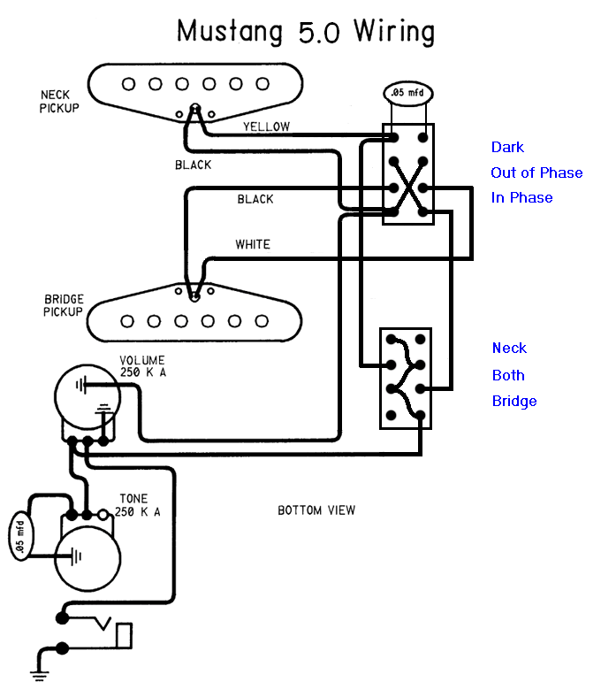 Needs to be vetted, though. |
|
|
|
Post by newey on Jun 19, 2012 22:00:38 GMT -5
Dang it, RT, I looked at this 18 different ways and couldn't get that to work out! It vets OK as I see it, should work as intended. It's a "Dark Override" set-up. +1 for this, it's a nice work-out of a knotty problem. Edrock, if you can live with the slight change from your original scheme, this should do it. You will still need to decide on a cap value, however. EDIT: Here's a truth table for the switching: 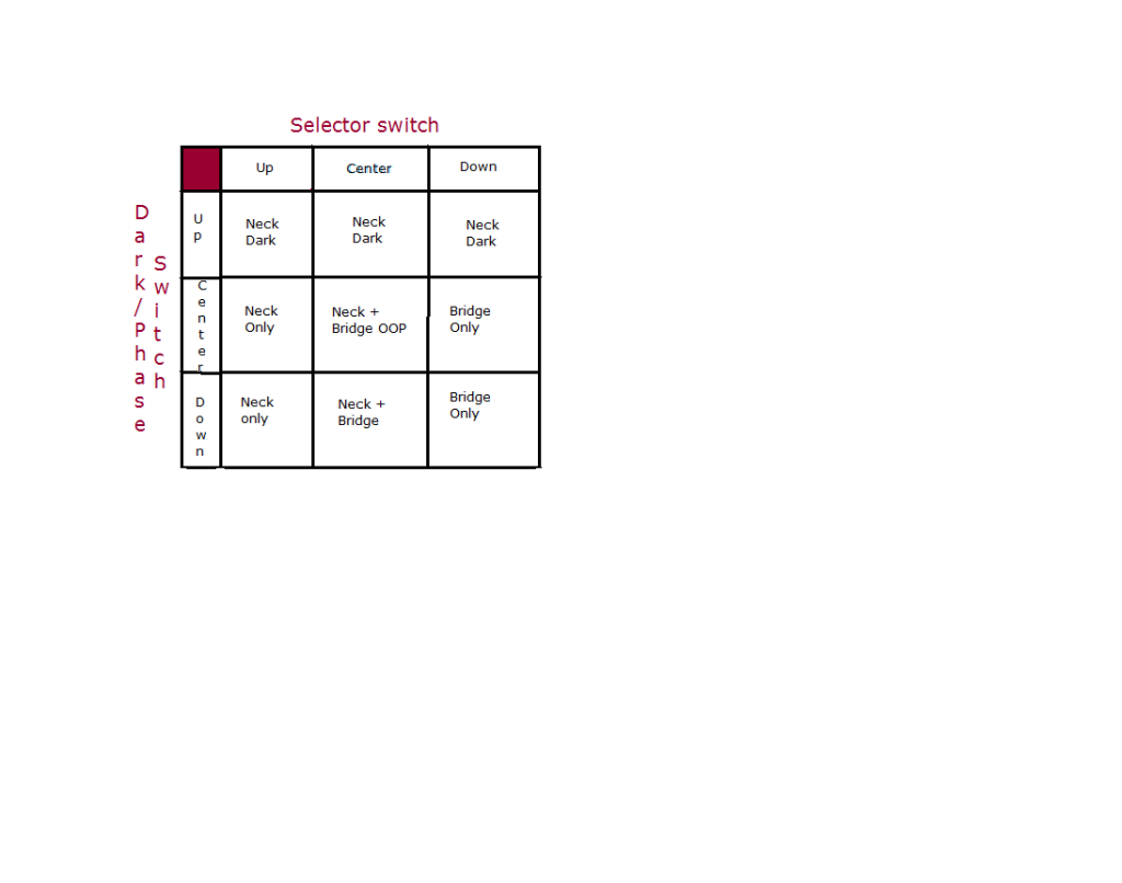 RT has shown a .05µf cap; as I noted, I used a .033µf. The original Fender Esquire wiring featured a cap setting for a "fixed bassy tone". Leo thought that the setting would appeal to Jazz players, who were mostly using hollow-bodied electrics (and still are). The original Esquire scheme had one .05 cap in series with a 3.3K resistor, with both in parallel with a second .05 cap. This proved unpopular because the output was lower in this position. A simplified "modern" Esquire wiring uses just a single .05 cap, just as RT shows in your circuit. Most folks who build an Esquire clone use this simplified wiring. .047µf is a standard value and would be indistinguishable from .05. Of course, both my travel guitar and the Esquire use this on a bridge pickup, so yours will differ being used on the neck. But there certainly is a precedent for the value RT suggested. My choice of .033 on the travel guitar was not based on any grand theory, it was what I had in the parts box at the time! |
|
edrock118
Rookie Solder Flinger
Posts: 7
Likes: 0
|
Post by edrock118 on Jun 20, 2012 4:54:08 GMT -5
Amazing! You guys are great. Looking at the table it works exactly as I dreamed of!
This easy swap is done by moving the neck's black cable and vol ground connection on lug 5 (clockwise denominations) of the neck switch and the connection between the two switches on lug 4 up to lug 7 and 2, right?
Which is the slight change? It seems pretty perfect to me, and I absolutely love the dark override, icing on the cake.
The Jag and Jazzmaster have .01 and .02 on various diagrams but after giving it a little listening research they seem quite low.
The Mustang already has a .05 on the tone pot, and the Jag has a matching .01 for rhythm and .01 for the tone pot, so maybe the .05 would suit in the same way.
I think the best way will be to experiment on the guitar, it's the only way to really know.
These subjective parts are the trickiest.
|
|
|
|
Post by 4real on Jun 20, 2012 5:20:14 GMT -5
Interesting solution and great it has met your desires. I put a 'dark' switch rather than a tone control on my last guitar... 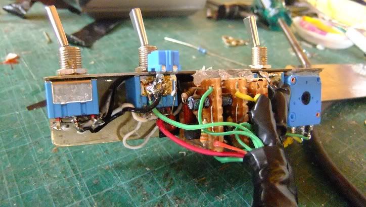 I don't recall the cap value, but I used a small trim pot in series with it so I could adjust to taste (just like a tone control) and perhaps that is something to consider. |
|
|
|
Post by newey on Jun 20, 2012 6:36:13 GMT -5
Thank RT, he did the heavy lifting here.
I meant the override as being the slight change. It does change your switching, in that if you're in the override and on the neck, it's two switch manipulations to get to the bridge or to the both settings. But it also allows you to preset the selector to the bridge and then go from dark to bridge (or both) with a flick.
But if you're happy, then everyone's happy!
No, then the neck pickup would be shorted out to itself ("hot" to ground) when in the dark position. Let's throw this ball back to RT, since he seems to have this option already visualized.
The cap on the tone pot is unrelated to the dark cap. The tone pot cap only comes into play as you rotate the knob; when the tone is at "10" it's out of the circuit for all practical purposes.
There is no logical reason that the two caps need to be of the same value, unless you're Leo Fender and you're making thousands of the things. Then, it becomes a big deal in terms of production costs.
Buy all the same value caps, and you get a discount on the larger quantity you buy- what an economist calls an "economy of scale". There is also a savings in having one less part to inventory, stock, etc. Save 10 cents a guitar, make 50,000 Jaguars, and put an extra 5 Grand in your pocket.
As I said earlier, the best way to experiment with cap values is to use a guitar cord and do it external to the guitar (assuming you haven't already dismembered your Mustang!)
If you have a guitar cable with a metal shield over the plugs, you can simple unscrew the shield to access the connections, and attach various caps across the + and - while plugged into your amp.
If all you have are cables with molded plastic ends, then you may have to sacrifice an old one to access the connections. Or, if you can access the output jack without removing the pickguard, you can test across the jack terminals.
If you want to get really fancy, you can also construct what is called a "cap substitution box" with in and out jacks like a pedal- I think you get the idea.
Best to do testing at the guitar end, so that the effect of the cable capacitance is accounted for. Make sure your V and T knobs are at the max when testing, and that you're set to the "neck only" position on the switches.
You may want to record your results to do a real A-B comparison.
|
|
|
|
Post by reTrEaD on Jun 20, 2012 7:43:26 GMT -5
This easy swap is done by moving the neck's black cable and vol ground connection on lug 5 (clockwise denominations) of the neck switch and the connection between the two switches on lug 4 up to lug 7 and 2, right? Sooooo close. That's two thirds of it. As Newey pointed out, the connection in the upper left corner would now become a problem. So that has to move to the upper right. The original Fender Esquire wiring featured a cap setting for a "fixed bassy tone". Leo thought that the setting would appeal to Jazz players, who were mostly using hollow-bodied electrics (and still are). The original Esquire scheme had one .05 cap in series with a 3.3K resistor, with both in parallel with a second .05 cap.
This proved unpopular because the output was lower in this position. A simplified "modern" Esquire wiring uses just a single .05 cap, just as RT shows in your circuit. Most folks who build an Esquire clone use this simplified wiring. Interesting. I've been toying with spice modeling for pickups and tone controls. Something odd happens when the cap is directly in parallel with the pickup(s). You get a slight midrange peak just before the treble rolloff. Using a 3~5k resistor in series with the 50nF cap prevents the peak. Smaller caps would require a larger resistor. About 5~10k for a 22nF cap. Of course this is based on the thought that you might not want a midrange peak. Perhaps you might like it. |
|
edrock118
Rookie Solder Flinger
Posts: 7
Likes: 0
|
Post by edrock118 on Jun 20, 2012 8:24:52 GMT -5
I'll have one more try: if the wires of the bridge pickup on the neck switch are swapped round then that should do it?
Luckily I have an old metal shielded cable so after a quick visit to the local odds'n'sods for some resistors I'll get testing.
|
|
|
|
Post by reTrEaD on Jun 20, 2012 8:39:55 GMT -5
I'll have one more try: if the wires of the bridge pickup on the neck switch are swapped round then that should do it? Actually that's more direct. It should work. You can do it either way. Moving the wires from the bottom of the X to the top of the X, and swapping the connections from 8 to 1. OR swap the Black and White of the bridge pickup. |
|
|
|
Post by newey on Jun 20, 2012 13:47:09 GMT -5
RT- at the risk of going somewhat off topic here: I assume you've seen this before, but here's what you're talking about. Chris used to refer to this effect as a type of "passive boost", since our ears preferentially hear certain frequencies above others. ChrisK's "Pickup Coil Response Tuning"Unfortunately, the links in this post went bye-bye some time ago, and IIRC sumgai doesn't have copies available to re-post. Which is a darned shame. If Chris were still around, he'd tell you that this was the most valuable contribution he had made to the forum. At least, that was what he expressed to me at our meeting. And he'd insist that we all read (or re-read) the article on which this work was based. |
|
|
|
Post by sumgai on Jun 20, 2012 16:04:12 GMT -5
Au contraire, mon frere!! The images were already on my PhotoBucket account (from last year), so either there's another page on these Forums with approximately the same info, or else ProBoards has, in their infinite wisdom, restored an earlier copy of the page, for who knows what reason. Either way, I've modified the page in question, so your link should be fully informative, as you intended. ;D HTH sumgai |
|


