|
|
Post by haydukej on Feb 8, 2013 13:48:46 GMT -5
The main objective of this thread is to build a preamp cable based off of JohnH's post on JFET Buffer and Buffer Cable thread. I've attempted to mod John's design by incorporating a TRS (or stereo) cable instead of the standard TS (mono) cable and converting the battery box into a FX-loop. Reasons for this are discussed later. This thread is also attempting to satisfy some secondary objectives. 1) My first attempt at interpreting a schematic into a wiring diagram. 2) Addressing the issue of my Strat Lovers Other Strat w/ FX Loop mod of not having the buffer built in the guitar. As Newey pointed out in my Strat Lovers Other Strat w/ FX Loop mod, the FX Loop would suffer loss-of-highs without a buffer built into it. Thus, Newey referred me to JohnH's buffer designs. The buffer cable seemed like a good fit as I did not want the buffer inside the guitar. However, to work with the FX loop mod, this buffer cable would need to be a TRS (stereo) type and not the TS (mono) cable outlined in John's design. I could not find a wiring diagram for John's buffer cable, only a schematic, which I can get lost in fairly easily. I decided instead of asking someone to draw me one, it was time to "learn how to fish" as some in the Nuthouse advise. Below I have included JohnH's schematic from his buffer cable thread and then my wiring diagram interpretation of it with my TRS mod incorporated. I would appreciate it if someone could check my interpretation of the circuit. General thoughts and comments are always welcome as well. I apologize for my crude MS Paint figure. JohnH's buffer cable (uses a TS-cable)  Haydukej's buffer cable (uses a TRS-cable) 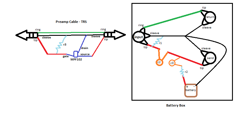 FYI for those not in the loop, pun intended. In theory this TRS buffer cable setup, used in conjunction with the Strat Lovers Other Strat w/ FX Loop, would take the guitar signal through the following path: selected pickups => TRS buffer cable => battery box => "send" jack => insert favorite FX pedals => "return" jack => TRS buffer cable (post buffer) => volume pot on guitar => second output jack on guitar => amp. |
|
|
|
Post by JohnH on Feb 8, 2013 14:37:58 GMT -5
Interesting thought. i was going to suggest building that preamp into the guitar, beacuse it is so simple, but It may be workable externally in which case it is a cool idea.
iI suggest that we should also ensure that the guitar can also work normally, without the loop, using a standard cable.
With the buffer cable, even in its normal use, it needs two core plus ground, so to get the return as well, it needs three cores. Ive used a four core cable of about the size of a guitar cable for some pup conversions, so something like that might be what is needed.
But I think it could work. Watch out for a very good jack plug that clamps the cable well, since what is inside such as the JFET wires, need to be protected from pulls etc
|
|
|
|
Post by ashcatlt on Feb 8, 2013 16:30:18 GMT -5
Note that C3 needs to be parallel to the battery - between +9V and the input jack sleeve. As drawn the cap will block the DC voltage and leave the transistor unpowered.
Note also that JohnH's design uses the stereo input jack to disable the battery when the cable is unplugged. Since you're using the ring for other things, you've got it wired to be always on, so you'll either need a switch to turn the thing off (actually disconnect the battery, not just bypass) AND remember to use it, or a TRRS input jack. Never looked for a 1/4" TRRS jack. The 1/8" versions are out there (used in iphones and video cameras) but I just don't know about the bigger ones.
And speaking of switches you may think about a true-bypass stomp switch for the loop. While you're at it, why not stick a feedback knob in there too? I don't know what I ever did without my feedback knob! This might then lead to another switch for engaging the feedback. On mine, I just cut the track on the pot a la "no load", but find myself now sort of wishing I didn't have to bend over to go back and forth.
|
|
|
|
Post by newey on Feb 8, 2013 17:15:54 GMT -5
I have, and I've yet to find one. However, switched TRS jacks are available and could be used to accomplish the same thing.
|
|
|
|
Post by haydukej on Feb 8, 2013 17:57:06 GMT -5
Ok, one step at a time. Does the updated drawing below address the c3 issue?  I'll try to add a power switch next for the battery if I've solved the capacitor issue. |
|
|
|
Post by newey on Feb 8, 2013 18:43:59 GMT -5
Looks like that takes care of C3. But also note that C3 is an electrolytic capacitor, and needs to be installed mindful of polarity. Your diagram should reflect that so as to accurately reflect the schematic, and also to remind you when you wire it that it goes one way.
|
|
|
|
Post by ashcatlt on Feb 8, 2013 20:16:33 GMT -5
Wait! Back up a minute!
You (sort of) fixed the C3 thing, but that leaves C2 in the way.
That makes me look back at JohnH's diagram and his comments re: his original needing 3 wires and yours needing four.
THAT leads to the realization that the original doesn't have an INPUT jack!
Apparently the cable is meant to be permanently attached to the battery box, with the jack pictured acting as the OUTPUT.
You should have your INPUT RING connected in place of JohnH's OUTPUT TIP, but you still need a TRRS cable and matching jacks on both ends (one of which wants to also be N/O switched, for the battery thing) in order to get all four wires connected.
Are you up for a total of 3 jacks in the guitar? Since the 1/4" version of TRRS is elusive at best, I'm afraid that's where you're at. You could, I suppose, go with a 4-pin DIN cable, or those funky 4-pin XLR type things...
Or you could build the buffer into either the guitar or the box and use a simple TRS send/return deal...
|
|
|
|
Post by JohnH on Feb 8, 2013 22:06:23 GMT -5
This is what you need:
At the guitar, a standard TRS socket, for send, return and ground. There is no power switching at the guitar.
Need a cable with at least 3 cores plus ground
Between the cable and teh floor box, you can hardwire with no plug socket - which is as shown in my design. But if you prefer to seperate them, then it needs a plug/socket suiatble for 3 cores plus ground. I wonder if a standard XLR coudl do this - since it has three prongs plus a barrel, even though its normally only used with two core mic cable.? Or, a TRRS plug/socket
You need two other jack sockets on the box for send and return. these can be mono sockets if you add a power switch, or, either one to be a TRS with the ring connection going only to battery negative, as shown in mine, to engage power when a mono plug is inserted. I think I would use both the TRS power switching, and have a seperate power switch so you can leave it plugged in but switched off.
John
|
|
|
|
Post by haydukej on Feb 8, 2013 23:14:09 GMT -5
So what I getting from the replies is that what I was thinking is possible with the correct, and somewhat rare?, parts. However, it is probably not the easiest method for what I was originally wanting to accomplish and in the long run, it looks like the easiest way would be with the buffer built into the guitar and then devise a Y-split box for the FX-loop (send/return). Well at least I think I learned a little bit of interpreting schematics and I might have stirred up some thoughts for others. So if I could attempt it, is the drawing below representative of JohnH's original design as shown in the schematic at the beginning of this thread? 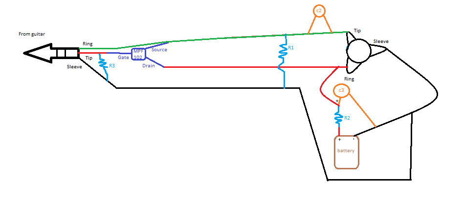 |
|
|
|
Post by ashcatlt on Feb 8, 2013 23:15:25 GMT -5
Oh yeah! Sorry about that. Only three of the wires get to the guitar itself, so only one TRS jack there.
Seems it would be easy enough to put two TS or TRS jacks in the box for input, rather than looking for 4 contact alternatives.
Edit - You ninja'd me! The answer is no. There are several things not quite right, but ive kind of run out of time to go through it right now.
|
|
|
|
Post by JohnH on Feb 9, 2013 14:58:25 GMT -5
Diagram is not quite there yet. If you want to start by just drawing the base design that I did, just take my diagram and put pictures instead of symbols..thats it.
Without a return added, the plug at the guitar is just a mono plug, or if it is a TRS, the ring would not be used. the green wire only goes to the JFET, not to the plug. At the other end, the battery negative goes only to the socket ring connection, it is not connected to anything else. C2 is curently shown shorted out.
|
|