|
|
Post by 0wnyourtone on Nov 30, 2013 21:27:15 GMT -5
I'd like to develop a control or set of controls which enables me to cut the bass of one pickup while cutting the treble of another pickup simultaneously and also pan from the brighter pickup to the darker. So, what I'd end up with is having the bass of one pickup and the treble of the other and a knob which panned between the two.
I wanted to tap your brains and see what suggestions y'all had for accomplishing this and perhaps try a few options to see what worked best. Any suggestions?
I've contemplated a rotary switch which had various frequency high pass and low pass combinations, perhaps combined with a tone pot or volume to get various shades and blends.
My inspiration is the "mixer" control on some Rickenbackers, but I would like to be able to shift the frequency corners if possible.
What say you?
|
|
|
|
Post by ashcatlt on Nov 30, 2013 23:09:12 GMT -5
This is very tough to do in a parallel configuration because just about anything you do to kill treble on one will kill treble in the other.
It's pretty easy in series. We call it "Broadbucker" around here, but it's really just a tone control across the "bass" pickup and does exactly what you're talking about.
|
|
|
|
Post by sumgai on Dec 1, 2013 0:39:09 GMT -5
0yt, As ash notes, you'd have to isolate the two pickups to avoid interaction as he described. However.... a mixer control will do exactly that - you feed the two pups' hot leads into opposing end terminals of a pot, then take the output signal from the wiper, feeding that to the amp (or other controls), etc. However, your total signal level is now quite a bit lower. Using a verifiable blend pot (sourced from Unobtanium-Parts-R-Us, to be sure) will actually not work in this case, as you'd still be tying the two output leads together, thus re-introducing the interaction between the pickup/tone-control assemblies. I'm afraid that you'll end up having to go active in such a scenario as you describe, but then again, that's not necessarily all bad - take a look at JohnH's treatise on low-power-consumption pre-amp circuits: John's JFET Pre-ampsHTH sumgai |
|
|
|
Post by ashcatlt on Dec 1, 2013 15:04:53 GMT -5
Yeah, sorry. I posted really fast last night. I will never understand how a woman can sit and look at her screen and ignore me until the exact moment when I get bored and start interacting with my screen. Now she wants to have a conversation with the dude in the room with her? So... It's not all that tough to do. It is pretty tough to do well passively. It's actually pretty easy to do in an active circuit. I hate the idea of requiring a battery to play my guitar, and think that individual outputs for the pickups is too much easier and more flexible to bother trying to cram even more crap into the control cavity. Now I have all kinds of Broadbucker tones all over the place (my Rick and my baritone, for example), and the only place I use them as a "go to" tone is on the bass. It can be a bit weird on the six strings. It is a little different from what you're talking about, in that you get all of the bass from both pickups in series, but the treble of the one pickup by itself. Kind of. A lot of times the top end sounds just feeble, like too bright but weak on top of the fairly powerful low end. It's an acquired taste on a six string, a special effect thing for specific situations. I find it actually works better clean, at least for me. When I just want to rock, I go for standard parallel or series settings. It's pretty cool on the bass, though, probably because the "action" happens in a region that is less crucial to the instrument. The parallel version that you're talking is a bit different, though. You seem to have a decent grasp on some of the concepts involved, but I just want to point out that you've got not only amplitude, but also phase to consider hear. The harmonics in the middle of the spectrum already have a random phase relationship between the two pickups. Anything you in the analog realm to filter either pickup will introduce its own frequency dependent phase delay. So there's that... Ok. There's this 5-year-old who was full two minutes ago, but is really hungry now... |
|
|
|
Post by 0wnyourtone on Dec 1, 2013 23:28:13 GMT -5
Thank you for replying guys. You raise some good points I hadn't thought about much.
Well, truth be told, I think I'd be happiest with something which acted like the "mixer" control on a 5-control Rickenbacker, but without actually having 5 controls. With the mixer control, which is essentially an extra neck pup volume, you can pan from the what sounds like the neck pickup with the tone rolled all the way (or the darkest, bass-heaviest sound) to the bright bridge and anywhere in between. The trouble I've had with that is, I get stuck when trying to simulate the 5-control circuit with fixed resistors, rather than the individual pickup volumes. If I were to succeed at this simulation, I ideally would end up with a master volume, a neck tone pot or switch and a mixer control which attenuated the bass-heavy neck pup.
I'm too lazy to upload the Rick scheme from my phone right now, but it can easily be found on Rickenbacker's wiring page as a "5 control" circuit.
I'd like to stay passive if possible, but if that pursuit fails, I'll happily explore something active. I don't mind the battery, I just miss the dynamic sensitivity I get from bumping those electrons with my bare... pick.
|
|
|
|
Post by JohnH on Dec 1, 2013 23:39:13 GMT -5
I could see it working with: A neck pickup with a normal treble cut tone control across it (or a fixed cap - depending on if the treble cut is to be adjusted) A bridge pickup with a bass cut control - ie a very small cap in series (maybe 2nF)and a resistor, about 220k to ground. A pot across the cap to reduce the amount of bass cut pan between them with a 500k linear pot, wired with an active buffer, like this: Active blender modulecheers John |
|
|
|
Post by 0wnyourtone on Dec 1, 2013 23:47:26 GMT -5
0yt, As ash notes, you'd have to isolate the two pickups to avoid interaction as he described. However.... a mixer control will do exactly that - you feed the two pups' hot leads into opposing end terminals of a pot, then take the output signal from the wiper, feeding that to the amp (or other controls), etc. However, your total signal level is now quite a bit lower. I wonder how a mixer (standard pot) set up as you describe, would perform parallel to both pickups in parallel? So, you'd have the full signal of both pups along side the mixed signal. The idea there would be to maintain volume, yet create a "leaning" of volume toward one pickup. Still doesn't solve the tone-isolation issue, even if it worked. |
|
|
|
Post by 0wnyourtone on Dec 2, 2013 0:11:27 GMT -5
I could see it working with: A neck pickup with a normal treble cut tone control across it (or a fixed cap - depending on if the treble cut is to be adjusted) A bridge pickup with a bass cut control - ie a very small cap in series (maybe 2nF)and a resistor, about 220k to ground. A pot across the cap to reduce the amount of bass cut pan between them with a 500k linear pot, wired with an active buffer, like this: Active blender modulecheers John Cool suggestion. My knowledge of electronics is quite crude in the sense that I have only done a bunch of experimentation with passive guitar stuff. Jumping to active doesn't appear too tough, but I'll have to do some study on unfamiliar components and such, to fill the gaps in knowledge. This appears simple enough I just might try it. John, if you wouldn't mind reviewing my comments about the 5-control rickenbacker scheme, I'd be curious as to your thoughts there too. |
|
|
|
Post by sumgai on Dec 2, 2013 0:41:52 GMT -5
I wonder how a mixer (standard pot) set up as you describe, would perform parallel to both pickups in parallel? So, you'd have the full signal of both pups along side the mixed signal. The idea there would be to maintain volume, yet create a "leaning" of volume toward one pickup. Still doesn't solve the tone-isolation issue, even if it worked. It works because the full "mixer" pot's value (250KΩ, or whatever) remains between the two pup hot leads at all times - there's your isolation. (In point of fact, inside of most PA mixers, it's usually 82 or 100KΩ that's used for this purpose.) The wiper is merely giving preference to one pickup or the other to send to the output, as dictated by the user, but that isolation resistance value never changes. In point of fact, all of this would be easier to do in series. Therein, a pair of shunt pots, (a "dual-gang" pot that has two resistance sections on one shaft/knob) can easily turn down one or the other pup without affecting the other quite so much. This is called a pan pot, but what you actually want is properly called a blend pot. (A short discussion on the differences can be found here: Pan vs Blend Pots) In this scenario, you intentionally connect the two wiper outputs, as they well be then hooked between the two pups, not to the output (Master Volume, output jack, or what-have-you). Of course, the potential downside is that you may not like the sound (Tone) of the two pups in series - some do, some don't. Food for thought.... how's your digestive tract?  sumgai |
|
|
|
Post by 0wnyourtone on Dec 2, 2013 1:12:01 GMT -5
I wonder how a mixer (standard pot) set up as you describe, would perform parallel to both pickups in parallel? So, you'd have the full signal of both pups along side the mixed signal. The idea there would be to maintain volume, yet create a "leaning" of volume toward one pickup. Still doesn't solve the tone-isolation issue, even if it worked. It works because the full "mixer" pot's value (250KΩ, or whatever) remains between the two pup hot leads at all times - there's your isolation. (In point of fact, inside of most PA mixers, it's usually 82 or 100KΩ that's used for this purpose.) The wiper is merely giving preference to one pickup or the other to send to the output, as dictated by the user, but that isolation resistance value never changes. In point of fact, all of this would be easier to do in series. Therein, a pair of shunt pots, (a "dual-gang" pot that has two resistance sections on one shaft/knob) can easily turn down one or the other pup without affecting the other quite so much. This is called a pan pot, but what you actually want is properly called a blend pot. (A short discussion on the differences can be found here: Pan vs Blend Pots) In this scenario, you intentionally connect the two wiper outputs, as they well be then hooked between the two pups, not to the output (Master Volume, output jack, or what-have-you). Of course, the potential downside is that you may not like the sound (Tone) of the two pups in series - some do, some don't. Yeah, I'm pretty attached this particular set of pickups, Filtertrons, in parallel. I have messed with an M/N blend pot before and I wasn't impressed, although I hardly rule them out altogether based on one experience with one pot. That's interesting about the pup isolation. I sure wish there were a good way of isolating pups in parallel passively! I get that isolated vibe from the Rickenbacker 5-control setup, but I don't want to drill a bunch of holes for the controls I wouldn't use. I have gotten the parallel blend I like (without tone-shaping) using a C50k pot to attenuate the neck pup over a 3.3Meg resistor. So, the 3.3M is sort of the "bottom half" of a voltage division and the 50K pot slides the neck volume back very smoothly and gradually until the bridge pup dominates, almost exclusively. I also like the 3,3M because I get very little treble or volume loss when I switch to the neck by itself, no matter where the 50K is set. I call it the "smooth shave" control and find it a good alternative to individual pup volumes. If I could get the smooth shave to work with an isolated neck pup with a cap across it, that would go a long way toward getting where I want to go sonically. How the heck does Rickenbacker do it? I think it may be the way their pickup switch works or various static resistances provided by the multiple volumes isolating the pup tones. Here's their scheme: www.rickenbacker.com/pdfs/19512.pdf |
|
|
|
Post by 0wnyourtone on Dec 2, 2013 9:24:33 GMT -5
Upon further review of the Rick scheme, it appears to me that their pickup switch has two inputs and outputs, isolating the signal paths before the volumes. If my memory serves me right, I think a standard Les Paul-type switch could function this way if you did NOT solder the two middle tabs together as the output, like is normally done. Does that sound right? Am I on a good path here?
Then, with the switch isolating the signal paths, I would think one could simulate the treble and bass volumes (if they are aiding isolation of pickup tones) with fixed resistors? After that, I'd essentially be left with hooking up the mixer control and bass tone?
I've kind of reeled in my goal now - just looking to go from the bass ridden pup to the straight, unaltered treble pup... for now.
|
|
|
|
Post by ashcatlt on Dec 2, 2013 12:25:18 GMT -5
Your link is to the 3 pickup version, which pretty much just connects the neck and middle in parallel at all times. The two pickup version is here, but really I think they're about the same. Anywho, I think I figured out where you're at. TBH, I very rarely used that mixer control on my guitar, which is why I was perfectly happy to replace it when I rewired the thing. The reason I didn't use it is that IME it went from the straight middle position sound to one dominated by the bridge pickup, and that's what the switch does...and that's my clue here. I think that you are actually depending on the interactivity of the tone controls to get what you think you're hearing. See if you can follow me, here. With the mixer all the way to the "bass" side of things, the switch in the middle, and both individual Vs all the way up, you've basically got all of the pots connected together. If you turn down the neck pickup's T control, it's just hanging off the output jack and kills the treble from the entire guitar. You have the middle sound - both pickups in parallel - with the tone rolled off. When you turn the mixer toward the bridge pickup, it becomes the "top resistor" of a voltage divider with the two Vs (and the bridge pickup, it's tone control, and the cable capacitance, and whatever's connected at the other end of the jack...) in parallel as the bottom. So basically the neck pickup drops out far enough to essentially make no difference. More importantly, though, this control also "hides" the Neck T control behind its 500K resistance, making it a heck of a lot harder for it to suck the treble off the output. Turning down the Neck V itself accomplishes about the same thing, I think. If the two pickups were actually isolated to begin with, then with the mixer all the way "off" and the Neck T all the way down you'd still have all of the treble from the bridge pickup. It would not be a "bass heavy" sound, I think. Maybe it is just as easy as letting it do what it does.  |
|
col
format tables
Posts: 468
Likes: 25
|
Post by col on Dec 2, 2013 14:19:40 GMT -5
Hi, I'm not sure if there is any advantage/point to such an arrangement. It seems, when both pickups are selected, Oyt wishes the bridge PU to be brighter and the neck PU to be darker. If it makes a noticeable difference, there will be some scooping of the middle frequencies - is this what you are after, Oyt? For what it's worth, I have an idea which might work (sort of). I haven't sketched it out, so I might have missed something. What if you used a blend pot and a push/pull tone pot? The blend pot will isolate the two PUs when you turn it down a notch either way (treble-cut will operate fully on both PUs when in the middle). For 'scooped blend mode', use a pole from the push/pull to wire the treble-cut pot wiper to the neck wiper of the blend pot. As soon as you move off center with the blend pot, you will begin to isolate the two pickups and the treble cut will have most of its effects on the neck PU. Use the other pole from the push/pull to introduce a series bass-cut capacitor on the bridge PU. When the push/pull is in the normal position, the treble-cut wiper will be wired to the output, and the bass-cut capacitor will be shorted. You might find this page useful - especially if you decide to go for the series/parallel option: guitarnuts2.proboards.com/thread/3863/series-parallel-blend-dpdt-switch |
|
|
|
Post by sumgai on Dec 2, 2013 14:20:17 GMT -5
Owny, ash has it right, with two additional points: a) The two pup Volume controls are wired "backwards" - they isolate in that turning down one pup all they way does not kill all sound, only that pickup (when both are selected). Sadly my Google-fu seems to be uncooperative at the moment, I can't find the thread that details this little fact... perhaps a little help from my friends here, please? b) On your linked diagram with three pups, the mixer is grounded, on ash's linked diagram, it's not - that's an important difference. I'd venture to guess that without the ground, the loading on the pickup will be close to none, and thus the overall tone will remain a bit brighter. I also doubt the mixing action will be very noticible. With it grounded, the mixing effect should be more pronounced, though the tone might not be what one desires. Only a simple experiment (connected/not connected) will reveal which way you will sound best to you. Taken together, the backwards wiring and the (loaded) grounded mixer should yield the results you're after. If you don't want other controls, you can bypass them appropriately with hard-wired components, tucked under the pickguard for a clean appearance (from the outside, at least). HTH sumgai |
|
|
|
Post by ashcatlt on Dec 2, 2013 15:15:15 GMT -5
sg - I think if we can get 9 or 10 db drop on the neck pickup it'll be close enough to out of the picture. Just the 500K of the (ungrounded) mixer over the 500K of the NV drops 6db. With the BV parallel to the NV, we get -10db, right? Then there are other things in parallel with the "bottom end" like I said. Increasing that mixer pot value makes things even more dramatic.
I actually missed that one little detail of the grounding on that mixer. It will make a noticeable difference.
col - I think we've gone back and forth on what 0wn is looking for. Frankly, I think both paths lead interesting places, though both seem to point me toward separate output jacks...
|
|
|
|
Post by JohnH on Dec 3, 2013 13:40:00 GMT -5
I could see it working with: A neck pickup with a normal treble cut tone control across it (or a fixed cap - depending on if the treble cut is to be adjusted) A bridge pickup with a bass cut control - ie a very small cap in series (maybe 2nF)and a resistor, about 220k to ground. A pot across the cap to reduce the amount of bass cut pan between them with a 500k linear pot, wired with an active buffer, like this: Active blender modulecheers John Cool suggestion. My knowledge of electronics is quite crude in the sense that I have only done a bunch of experimentation with passive guitar stuff. Jumping to active doesn't appear too tough, but I'll have to do some study on unfamiliar components and such, to fill the gaps in knowledge. This appears simple enough I just might try it. John, if you wouldn't mind reviewing my comments about the 5-control rickenbacker scheme, I'd be curious as to your thoughts there too. My belief s that when you do more than a minimal set of passive controls, you tend to lose something as the signal gets weaker, or more vulnerable to treble loss or noise. by this I mean having more than one level of volume or blender controls between output and pickups, or complex tone controls that prevent a direct connection of pickup to volume. But there are plenty of Gretsch and Ricky owners who may feel obliged to disagree. The idea I described above is worth modelling, so I intend to do that in order to determine whether my hunch is any good. |
|
|
|
Post by 0wnyourtone on Dec 3, 2013 20:05:33 GMT -5
Thanks everybody! What a wealth of valuable input!
I owned the 3 pickup Rickenbacker at one point and enjoyed the specific use of the mixer for panning from a bass-heavy timber to the treble pickup.
I understand where you are coming from John, with overloading the pickups and the susceptibility to excessive treble loss. While I did enjoy the timbers yield from the Rick controls, I am dealing with a different guitar and would not presume to have a comparable result without some tweaking of component values at least. I am interested in the results of your model, for sure.
When I mess with a guitar, I usually try to start with a clear, balanced objective(s) and try a variety of methods for arriving at my goal. So, I am appreciating all the perspectives and angles y'all are giving here.
So, to reiterate, my main goal is to pan smoothly from a bass-heavy, neck/both pickup sound to the treble pup. Bass cut is something I currently have as a global control on my Guitar and I simply have a curiosity as to what sounds I could get from isolating it to one pickup. I initially thought about being super fancy and taking a movable crossover approach and I'm still open to the idea, but I want to keep the main goal in sight: neck/both dark to bridge bright.
|
|
|
|
Post by 0wnyourtone on Dec 4, 2013 8:59:58 GMT -5
So, now that I've slept, I think will attempt all or most of the above ideas - even experimenting with dual outputs, Ash.
In the dual output scenario, it would be quite easy to effect the pickups independently and passively, so that makes sense to try. I suppose the only disadvantage there could be more physical controls onboard and more signal routing and effecting after the guitar, but I'm still interested.
The blender and/or mixer pot idea seems cool, in the sense that a single control does a lot, like I want. I worry about lack of volume in the middle though and the smoothness or controllability of the pot(s). Still, you have the isolation yielded by the backwards-wired dual gang which would appear to get the job done.
Appearing to have the simplest performance, with the best insurance of signal integrity, is the active buffer idea. This leaves all sorts of possibilities as to effecting the independent signals without much worry for isolation also. I'm kind of leaning this way a bit more as I debate internally. I'll await your results on the simulation-model thingy there, John.
|
|
|
|
Post by JohnH on Dec 4, 2013 14:30:50 GMT -5
Hi OYT
I did my model, but I haven't time to upload it before leaving for work this morning since I need to add some software to this new pc to do it.
But with some value tweaking, It worked out well, or at least interestingly. At mid blend, you can set up a flat response from bass to treble. Its about 6bd down, so a buffer with gain to bring the level up may be ideal (its a different single JFET circuit, but just as simple). From there, you can swing the response to bass boost/treble cut, or bass cut treble boost, each with about +/-6db swing. In each case, the highs come from the bridge and the lows from the neck. I think it might be a cool control on a guitar with just this blend/tone knob, and a volume control, no switches at all.
If the bass cut and treble cut sections also have their own controls to remove those effects, it can morph to being a straight linear blender between full bridge and full neck.
|
|
|
|
Post by 0wnyourtone on Dec 5, 2013 1:35:15 GMT -5
Hi OYT I did my model, but I haven't time to upload it before leaving for work this morning since I need to add some software to this new pc to do it. But with some value tweaking, It worked out well, or at least interestingly. At mid blend, you can set up a flat response from bass to treble. Its about 6bd down, so a buffer with gain to bring the level up may be ideal (its a different single JFET circuit, but just as simple). From there, you can swing the response to bass boost/treble cut, or bass cut treble boost, each with about +/-6db swing. In each case, the highs come from the bridge and the lows from the neck. I think it might be a cool control on a guitar with just this blend/tone knob, and a volume control, no switches at all. If the bass cut and treble cut sections also have their own controls to remove those effects, it can morph to being a straight linear blender between full bridge and full neck. Yeah! The tone circuitry could switch out on a Volume push pot or the like. I like that - seems simple and unique, but also has a practical vibe to it. Good contender! Briefly, another idea festering in my brain I'd like to air about this is the possibility of varying the frequency crossover point, where the low pass corner of the bass pup meets a high pass point of the bridge pup. Could this be practical or even doable with a control? Ideally, I would want a smooth, sweepable control which simply made the crossover point go from low (maybe 200Hz) to high (maybe 2.5kHz), but if that weren't doable, perhaps a multi-pole rotary switch with different series and parallel capacitor combos available on each pickup. I could see a neutral position as well, where no tone circuitry were involved. So, perhaps one end of the dial low passed the bass pup heavily while high passing the treble pup lightly and moved toward no tone coloration in the middle position, finally flip-flopping toward the latter end of the dial, where the treble pup would be low passed and the bass high passed more and more. Is this too crazy? I guess it's a different animal than we've been talking about. I could see a four pole rotary handling it, where two poles handled high passing and two poles handled low passing. Hmm. This may be a big can of worms, I have no idea. I'm too curious sometimes! |
|
|
|
Post by JohnH on Dec 5, 2013 14:00:02 GMT -5
Here's what I was on about:

As shown, its in fully 'neck treble cut and bridge bass cut' mode, and the traces show the blend pot at 25% increments. The values have been tweaked so that the mid position (red) is about linear.
What such models don't know about, is the inherent difference in tone from neck to bridge, so the real differences as you sweep would be more marked.
A dpdt switch to bypass C8 and make a break at R4/C3 will convert it to a linear blend between the two full pickup sounds.
In the blue boxes, the pickups are modelled, so these are not actual physical components. R4 is like a treble cut tone pot not quite at 0, since this seemed to make a better thing to blend with. The active buffer is not modelled here, but its input resistance is represented by R11, and its linear, so imagine it keeping the frequency response plot intact, but lifting it up by a chosen amount, say 6db. This is the type of circuit:
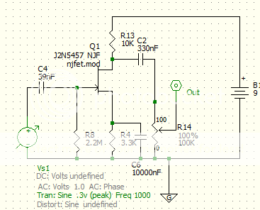
Probably without C6 and with values adjusted to suit whatever JFET you can find (we can talk more about that)
You noted about possibly changing the corner frequencies, and I think the caps C3 and C8 are the places to do that, so it would best be done with a rotary or three position toggle, and could be done separately for each pickup. How about a three-position toggle for each pickup that gives two cap values and also does the bypass mode for the full pickup sounds? Total controls woudl be volume, blender and two small toggles.
cheers John
|
|
|
|
Post by 0wnyourtone on Dec 6, 2013 2:00:18 GMT -5
Thank you for the work on the model; I'm impressed!
I like the flat response in the middle and the general frequency range of the crossover.
Your point about the model not accounting for the pickups' frequency response interaction with the components hits home. I always do some ear-testing different cap values to make sure I like the resulting sound, using the model as a starting point, since it's all about the sound and feel anyway, which is verified by listening and playing.
The "tone bypass" switch (or position) is a must have and I would likely remove the pup switch altogether, moving to solely to the JFET blend. Although, I do like the instant switch from one pup to another live.
I don't quite get how R4 works yet, but your explanation of what it does makes sense to me.
I'm not sure how I want to handle varying frequency corner yet, but I see the merit in individual pup-tone switches and perhaps the including of a tone-bypass position there, rather than a push pot, perhaps. I've got a few things to consider there. It's a ProJet, so the top is thick and won't handle mini toggle bushings. I need to decide how many throws I want and whether I want to offer bass cut and treble cut on both pickups, yielding the ability to flip-flop the bass pup and treble pups' tonal roles.
I'll do some more pondering and come back later.
Thanks again, I am humbled by your gracious help!
|
|
|
|
Post by 0wnyourtone on Dec 7, 2013 9:43:53 GMT -5
Hey guys, as I'm trying to brush up on some of the active components/symbology for the JFET circuit, do y'all have any recommendations for simple, concise reading on the subject?
I've pretty well got the passive stuff down, so far as how the components work and interact, but haven't dove into the active stuff yet.
|
|
|
|
Post by ashcatlt on Dec 7, 2013 10:53:30 GMT -5
Start with wiki and then hit google. In this configuration, the JFET is basically a voltage controlled resistor which acts as the "bottom resistor" (with r4 || c6 in series) of a voltage divider which modulates the 9V DC source to follow the input. The "top" of that divider is R13.
There are a few things that the model doesn't really address.
1) The component values in the pickup models are essential to the action of the filters. In fact, they very much are part of the filters. And the values John used are arbitrary. I mean, I know John has put a lot of research into finding realistic values for real world pickups, but it would be a complete accident if they matched yours. Even more fun is that it's not a lot of fun to figure out those values - specifically the inductance.
B) It models only the frequency response of the filter itself. Yeah, obvious. But we're not putting white noise or perfect step filters through the things. The harmonic proportions are completely different at the two pickup positions. The fundamental swings a lot more further than the higher harmonics at the neck pickup than at the bridge. The bridge is not usually brighter because of anything in the pickup circuit itself. In fact, very often the bridge pickup is hotter and therefore darker than the neck. But the higher harmonics are louder in comparison to the fundamental because we're closer to the anchor point. And...
III) As I mentioned earlier, the various harmonics have what is basically a random phase relationship between the two pickups and will add or cancel in unpredictable ways. This is dependent as much on where you're fretting as anything else, and can't really be modeled at all.
All that said, it is some intriguing results.
|
|
|
|
Post by JohnH on Dec 7, 2013 15:09:30 GMT -5
All true what Ash says.
On pickup effective values, not all suppliers give inductance values, but there are enough that do to give useful guidance for results, and usually about 2.5H for a single coil, 4H for a PAF style humbucker, or 6 to 8H for a hotter one are fair ball-park numbers. The pickup capacitance values are small and although worth modelling, are not too critical to the results we seek. Resistance you can measure easily and is somewhat of a guide to inductance if that is all you know. There are various reasons why resistance and inductance may be not directly related, but for most normally wound pickups, if you see a 14k resistance it will also have a high inductance. If you have some pickups in mind, appropriate values could be adjusted - the modelling done here has used roughly single-coil properties.
(btw - Ive never worked out what appropriate modelling would be for some of the stacked or noiseless singles - anyone with any insight on this? - one would expect higher impedances, commensurate with how some talk of a slight loss of single coil 'sparkle' in noiseless versions)
These values are not so critical for modelling in terms of whether a circuit works or doesn't work at all, but are good starting points for investigating a design, after which it should be tweaked by ear. When I have used such models before to design, and then test, I find that sometimes the favoured values end up one or two steps away from what the model might suggest based on listening rather than looking at a graph. Sometimes it works out bang-on, such as when I was checking out treble bleed circuits, the modelling led to some values that worked better than the standard ones that I had expected.
Here are the best references I've seen:
buildyourguitar.com/resources/lemme/index.htm
buildyourguitar.com/resources/lemme/table.htm
JFETs
yes better start with wiki etc. But here's how I see them, in relation to the circuit posted above. Try swallowing these statements one at a time with meals:
1. JFET = Junction Field Effect Transistor. They are not sensitive to static, reasonably robust and can be safely handled like any other component (unlike MosFETs - which can get zapped unless precautions are taken)
2. Three leads: gate (with the arrow), source (lower connection), drain(top connection)
3. The gate has very high input resistance, >10M, so virtually no current flows into it, it reacts only to voltage.
4. The path between source and drain acts like a resistor, dependant on the voltage between source and gate. It varies from extremely high, down to about 500 to 2k ohms (depends on type).
5. with a 2N5457, if the gate is about 2.5V or more below the source, the source/drain connection is very high resistance. In our circuit, the output will then be taken high by R13.(gate voltage down, output voltage goes up, its an inverting circuit)
6. As gate voltage rises, source/drain resistance falls, so output voltage falls.
7. Imagine no input signal. The gate is taken to ground by R8. The voltage at the source (lower connection on the JFET) has to rise until it is about 1.5 to 2V above the gate, at which point the source/drain resistance rises somewhat, and equilibrium is found. This is the bias point in which the JFET is partly on and some current is flowing.
8. We chose values so that this bias point has drain voltage just over half of the supply voltage.
9. Assume C6 is omitted. Now, if the gate voltage varies with signal, the source voltage approximately tracks the gate voltage variations, keeping equilibrium. Current through source/drain varies in relation.
10. The voltage variation at the source is roughly (very slightly less) than the gate variation, resulting in variable current through R4. But the same current is also flowing through R13 which is larger. Hence the voltage swing at the drain (= output) is larger, and we have gain, which is the main point of the circuit. The gain is slightly less than the ratio R13/R4 (due to the internal resistances)
11. Now consider C6, which bypasses R4 for ac signals. It effectively reduces impedance at R4 for ac, without affecting dc bias, increasing the ratio, increasing gain.
12. Getting such a circuit to work well is mainly to do with biasing it right so the output is sitting near mid supply or a bit more, so that voltage swings can occur from almost max +, down to a minimum based on the JFET being completely on (about 2.5V in this case, based on R4 and R13)
13. If we adjust R4 and R13 keeping them in proportion, the output and gain doesn't change much (may even increase slightly since internal minimum resistance gets less significant), but the circuit is less able to drive current = has a greater output impedance. As shown, the circuit is good for driving the 100k volume pot and then giving a robust output to a guitar amp.
cheers JH
|
|
|
|
Post by JohnH on Dec 7, 2013 19:48:12 GMT -5
Here's a bit more on possibilities for this set up.
If you had a 2p6t rotary, you could have five positions changing the key cap values, and a 6th to cut them out letting the full pickups through. Those five sets of cap values could move the two corner frequencies either apart, creating a gap resulting in a mid cut, or make them overlap, forming a boost in the mids.
Here it is, with blend at 50%, stepping the caps from 56nF/1nF for mid cut, to 10nF/3.3nF for mid boost:

Set to full mid boost, you can then pan the blender pot to control the mix like this:

Or with mid cut like this:

So the rotary switch and the blend control together could make a fairly powerful tone-tweaking combo.
cheers
John
|
|
|
|
Post by 0wnyourtone on Dec 7, 2013 21:18:40 GMT -5
You guys have given me a good sense of what I need to understand better. This is a busy few weeks surround Christmas, so I will likely not be able to delve as much as I want to into the content immediately. I'm audio engineering a Christmas production here in Kansas City the 15th, so it's family and rehearsals basically. But, I have a knack for not letting a lack of immediate understanding detour me from a quest.  Anyhow, John, your particular ideas for the practical tonal applications of the control, through varying the filtering combos is what most excites me about this project and inspired it in the first place, partially. The other part being the particular Rickenbacker I owned. Ash, as an audio engineer (music recording predominantly), I really related to what you were saying about the variables that contribute to an initial sound and how one can use his or her ears to mold that sound to their will. I am a particular fan of parametric EQs and get a similar vibe from this project for some reason. Perhaps the similarity is in the filtering and moving frequencies around. I also get a kick out of how pickups essentially do a lot of that work for you in their positioning and I like the idea of zoning in on what a pickup is doing harmonically and stealing a chunk of those frequencies to throw into a unique sonic recipe, such as could be offered in this project. |
|


