yaux0005
Apprentice Shielder

Posts: 31
Likes: 0
|
Post by yaux0005 on May 9, 2014 1:31:18 GMT -5
|
|
|
|
Post by Yogi B on Oct 31, 2014 13:29:37 GMT -5
The first of these schematics (the Stracciatella) really intrigues me as, even after reading the explanation from the thread where the diagram was posted, I cannot fathom why the circuit sounds as illustrated in the video. Even ignoring the interesting use of Schottky diodes (the treble bleed components bypass them anyway) I can't get past the fact that as with most, if not all, attempts at applying treble bleeds to parallel independent volumes when any of the volumes are turned down the treble bleed resistor / capacitor are connected in parallel with the output -- bleeding the treble to ground. In order to try and understand what is going on I simulated the circuit in LTspice seemed to only confirm my opinion, although I accept that this could be due to the limitations of spice modelling. What am I missing? |
|
|
|
Post by JohnH on Oct 31, 2014 15:32:25 GMT -5
Hi Yogi B - I completely agree with your puzzlement over that circuit, particularly the treble bleed concerns, where, as you noted, when you turn pickups off, with this 'independent' wiring, the caps and resistors are shunting all the treble signal. My suspicion is that that feature was not installed, or is not being revealed in the vid.
Diodes in a guitar circuit, for the purpose of separating pickups make no real sense at all unless we seek a distorted sound. These schottky's are sometimes put across the output from hot to ground to achieve that, and they sort of work.
In this application, they are in-line with the signal, between pickup/pot and output. A perfect on/off diode would be clipping half th signal off in this case. But real diodes are different. Most of the signal levels coming out of a guitar are very low, 0.1V or less except at transients, and in this case, very small/tiny/negligible currents are flowing into the high resistance of a guitar amp input. So the question is, what are the real characteristics of the diodes around these very small levels?
All diodes have a log relationship between voltage drop and current. I did some investigating on these a few years ago checking out diodes for distortion circuits. At a given current/voltage across the diodes, one can divide one by the other and get an effective 'resistance', which varies with signal level. As you go into negative current flows, the diodes cut off, becoming very high resistance. But at very very low currents, as they cross the zero axis on a graph of voltage v current, normal silicon diodes are behaving as if they have a resistance of several megaohms. That would be enough to seriously mess with the signal in this circuit..but...
...schottky diodes, have an effective resistance at zero current of around 70 to 80k, if I remember right. That is enough to let most of the signal through when it is only driving into an amp input impedance of about 1M. But, I don't think it achieves anything useful, beyond what a resistor of about that value would do there.
|
|
|
|
Post by sumgai on Nov 1, 2014 12:25:46 GMT -5
John replied succinctly, so I'll just dredge up a ChrisK-ism: GeFooey!  As for the second of those two links, I'll only add... this is what you get when you play hookey from Engineering school. The truth table is pretty far from the reality of that simplifed mess, and it doesn't take an EE to see why. I think most Nutz hereaboots would've used more tact than I just did when explaining the several built-in failures to that diagram's designer, were he/she to have posted it directly to The NutzHouse. In short, for all you viewers out there; there's a right way to do things, a wrong way to do things, and the Nutz way of doing things. For the most part, the real, and not hidden, facet to circuit design is to apply logic to achieve one's desires. Call me egotistical, but the whole premise of Nutz-ness is to apply logic where needed. In my purview, that means that you accept some compromises where necessary, because your priorities are leading you to achieve one particluar thing, and all else is of secondary consideration (ex. getting all sounds possible at the expense of ease-of-use). Stated more simply - apply logic first in your design(s), then execute on that logic. In between those two, though, I'd add that one should apply some strenuous Peer Review. And that is the right way to do things.  HTH sumgai (Note to newey: Finally, I found a valid use for the 'puke' smiley.) |
|
|
|
Post by JohnH on Nov 1, 2014 16:12:19 GMT -5
I think the second diagram, the 'Stratomaster', is not entirely too bad though it does have a few hairs. The merits of it are that it uses exactly what is on any stock Strat, and lets you try N+B blends, and also putting M in series, all with minimal wiring and no new parts. It works IMO, and it is useful as a way to test these effects.
The issues with it are that the blend pot doesn't quite switch off, for which it should be no load, and the series/parallel pot adds some loading to the tone, and feeds the signal through resistances unless at the ends of the pot travel. But I think it still works, even though a switch is a better way to do this. Also, one must give up both tone controls in this design.
Having experimented with this scheme, a keen proponent would be well advised to go an extra 1/10 mile and add a couple of simple components (switch, no-load pot) to do any of a number of other better but still very simple schemes that work in much the same way to achieve the same ends. A tone control can then be reinstated. We have several such schemes on GN2. |
|
|
|
Post by sumgai on Nov 1, 2014 22:56:25 GMT -5
John,
The two worst things I can see are that the so-called ser/par pot drastically reduces the output level of the Bridge and/or Neck pups, when not exactly at 0 or 9; and the truth table for "looper mode" is incorrect at Pos 2 and 4 - the Bridge and Neck pups will be shorted, just like they are in the so-called "burst mode". Hence, the truth table for positions 2 and 4 is exactly the same for both modes, meaning there's even more duplication going on.
Aside from alleviating the reduced N/B output if you replace the ser/par pot with an SPDT switch, there's still the N/B shorting problem, no matter how we slice it.
Further, out of 20 possible combos (of 0 or 9 on PB and PC), after all the duplication (I see no less than 8 times that we get Mid only!), I see only 10 differerent combinations. That's a lot of work for only a 50% return on investment, IMB (in my book).
Sorry if I sound like I'm peeing in someone's Cheerios, but I'm thinking that this modder must really like the sound of his Middle pup. Enough so that he was satisifed with a design that neither your or I would call Nutzworthy. Although to give credit where it's due, this thing does represent a reasonable starting point.... IMO it's just not finished, that's all.
sumgai
|
|
|
|
Post by Yogi B on Nov 2, 2014 1:25:45 GMT -5
John- Thanks as always for your thoroughly informative reply, as for not being installed: looking later in the thread there is a picture of the physical wiring which appears to tie in with the diagram, this was the first thing I checked -- that there wasn't an error in the production of the diagram, I can'r see why the version in the video would be different, or that this version was defective without a mention, but it could happen. I don't really see the thought process as to why the volumes were wired in an independent fashion, if the diodes were supposedly going to take care of that anyway, so in my messing with models of this design I also tried it with 'dependent' volumes, which had slightly better results but nothing I would classify as a success. Also in some cases BAT54 diodes seemed to work better that the suggested 1N5817/9. The reason I was looking at this was that I was thinking about one volume per pickup designs with potentially no switching options related to the number of active pickups active. Specifically I was searching to any better alternatives to the scheme I'd already come up with requiring dual gang pots with swapped out elements, this is it: 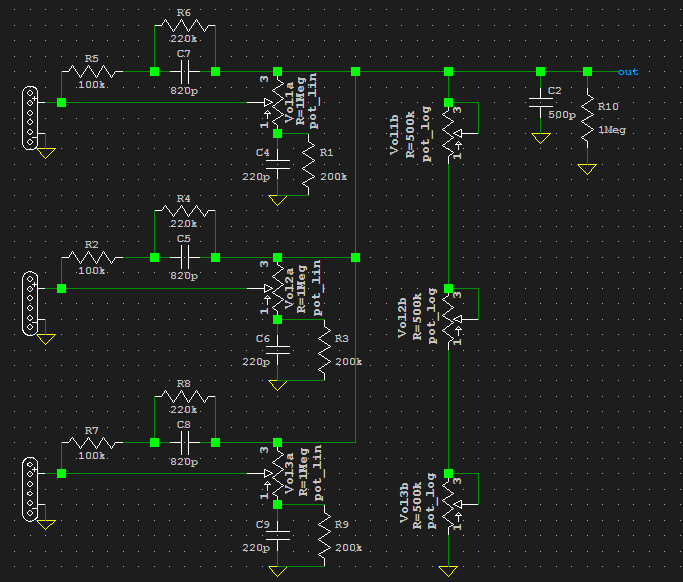 Adding the treble bleeds is tricksy since the pickups don't go all the way off (Edit: why I previously haven't thought to make the linear half of the potentiometers go no-load at zero, I don't know), but it appears that it would kinda work -- not that I'm thinking of incorporating this design into anything any more, however I still find the concept interesting. Sumgai- (Damn, you'd only replied once when I started typing this. 2+ hours, zip!) Regards the second diagram I again looked at the original thread ( here) and already noted John's replies there. However, this isn't really one that fits my guitar wiring ideology, at least not for now. For the most part, the real, and not hidden, facet to circuit design is to apply logic to achieve one's desires. Never has a truer sentiment been put forth... or something like that. I have previously mentioned to Newey in a PM, in the future (expectedly not as soon as I previously expected) I hope to have something precisely for this. |
|
|
|
Post by sumgai on Nov 2, 2014 20:50:00 GMT -5
yogi, I'll get to you in the next post, but for the nonce, I want to post an edit to Ben's OP, on this thread. (And thanks for the link to the original posting, over in the Strat-Talk Forum.) This is a corrected wiring diagram made by the original StratoMaster designer, as found over on the Strat-Talk forum:  Note that he has foresworn the Looper and Master modes, but indeed, he can still achieve the remaining combo to be found in Looper mode, so he still has 10 different combos (albeit only 9 are shown above). Nor did he change the nomenclature, the switches are still called pots in the truth table. But that's not worth diddling over, we still get his meaning, right? Further, our own JohnH is a member there, and he participated often during the discussion in that 3-page thread. I *think* John gently guided him towards recognizing the inherent limitations of a ser/par potentiometer, thus the switch-over to a switch (or two... he didn't really need to limit the Blend control so blatantly, that was never the problem). I will say this, in the OP's favor - he was very helpful, and very patient, towards questions from newbies and pros alike, he never once lost his cool. greekdude should be proud of his countryman. What it all boils down to is that Ben never updated his original posting above, (the Strat-Talk thread lasted for more than 3 months) so I've taken it upon myself to 'finish the story', so to speak.  I do hope that the design is now palatable to others here in The NutzHouse, as I see no other problems with it. In fact, I encourage those who are seriously curious to read that entire thread, one is bound to be driven to try this setup.  HTH sumgai |
|
|
|
Post by sumgai on Nov 2, 2014 22:12:56 GMT -5
Yogi, This time it's your turn in the barrel! The reason I was looking at this was that I was thinking about one volume per pickup designs with potentially no switching options related to the number of active pickups active. Specifically I was searching to any better alternatives to the scheme I'd already come up with requiring dual gang pots with swapped out elements, this is it: If that was your first draft, then I can't blame you for wanting to get past the few little problems, like the three "B" sections of the allegedly individual volume controls all being in.... wait for it.... series?  This is a gen-u-wine "What The... " moment in time, if you get my drift. I'm certain you thought it was a good idea at the time, but if you're already onto something else, then I'm more than willing to let it go. Now here's the real reason I'm scribbling these tidbits:No, sad to say, it won't. The reason a volume control works at all is that it is configured (wired up) as a potentiometer, meaning that it uses all three terminals, further meaning that it "channels", or sends, a signal to wherever the user decides (via mechanical rotation). The electrical term for this action is "voltage divider".... an incoming voltage is divided between two outputs (the two outer terminals), usually known as "hot" and what we call "ground". (Why is that last one in quote marks? Because the proper term is 'signal return', but everyone understands what the word 'ground' means, so that's what we use most often.) (BTW, the reverse hook-up is also true, that where an outgoing signal is hooked to the "top" terminal, and wiper chooses some fractional division between the full 'hot' signal and ground.) Now, you'll agree that a volume control (wired either in reverse or standard mode) uses all three terminals, right? So that means that we have a voltage divider in there, eh? Let's leave that for a moment, and go look at the standardized Tone control, which is nothing more than a treble-cut device. See where there are only two terminals in use? Well, that's because we need only control the amount of signal going through the capacitor, and nothing else. This configuration of a control is properly known as a rheostat. (And in point of fact, it does not control a voltage so much as it controls current, but that's a story for a different thread. ) So in a Tone control with a so-called 'no-load' cutoff at the upper end, we are essentially removing the resistance and the cap from the circuit entirely, not just leaving it with a large resistance still in series with the cap, to ground. Understandable so far, right? Good, because here's where you're gonna have a face-palm moment. That no-load "switch" is on the upper end of a rheostat, can you see that? Now, the magic question here is, what happens if you install a no-load "switch" on either end of a voltage-divider? Answer: you break the connection between the two outer terminal, thus rendering the control back to nothing more than a rheostat. I'm sure you can imagine, when you think about it, that this is Not A Good Thing. For reasons that I won't go into here (the electrical analysis is *not* simple, we need to do some math that goes well beyond Ohms's Law and such), it's best to leave track-cutting (making your own no-load pot) to tone controls, or other rheostat circuitry. The short answer as to why is that if you were to cut the track at the bottom of a volume control, turning the shaft would indeed reduce the apparent volume of the pickup, but the outgoing signal line would never reach ground. In turn, this means that it becomes what we call a "hanging hot", and is prone to picking up noise out of the raw air. (Not guaranteed, but more likely than not.) The one exception to that (track-cutting of a voltage-divider) is if you were to follow JohnH's suggestion about how to make a blend pot, in one of his more extravagant circuits. He lays out all the right reasons for doing so, and why it will deliver the desired effect (you'll be cutting in the middle of the track, IIRC). Other than that, I have one more thing to say.... Your diagram above... the three volume control "A" sections.... you show a cap/resistor network between the lower terminal and ground. Are you fully aware of the consequences of doing that? I mean, you somehow acknowledge that this changes the tone, but in what way, do you know? (Hint: it ain't what you expect, and it probably ain't desirable.) Aw shucks, you caught me out! But yer welcome! HTH sumgai |
|
|
|
Post by Yogi B on Nov 3, 2014 1:58:23 GMT -5
Sumgai- I read your post, I understood your post, but I still didn't see what was wrong, and so to best explain myself (albeit rather verbosely) I shall quote a post that never was: I'll start by explaining my initial thought process, as we both know the standard volume control is just a potential divider nicely packaged as a resistive track with a wiper attached to a twiddly bit good for frobbing... anyway originally in the context of potentiometer taper and treble bleeds I got started thinking about an inescapable truth of the single track & wiper design, the fact that the the resistance either side of the wiper sums to the pot value. I then started to think about two separate rheostats in place of the single potentiometer: 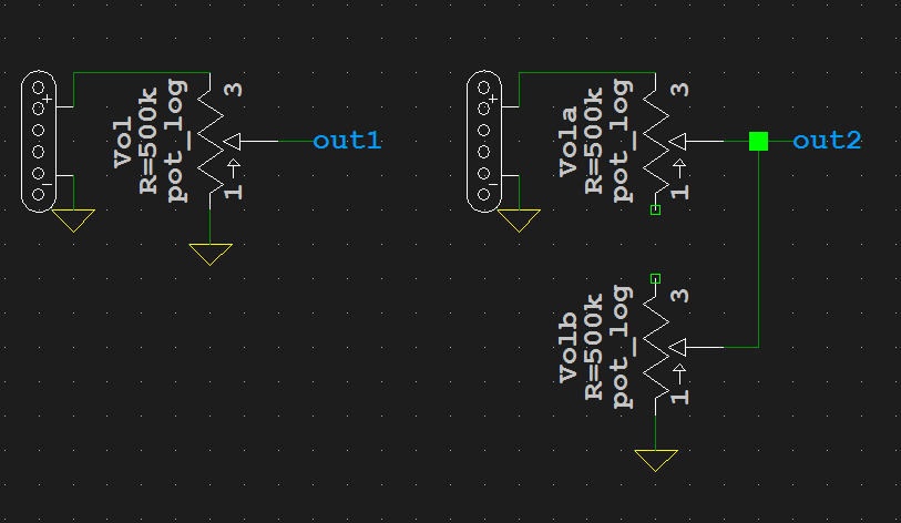 Now I had more flexibility: I could swap out each track for a different taper; rotate between having the output on the wiper or an outside lug; and possibly put the unused terminals to good use. With this extra flexibility I decided to see if I come up with a solution to the problems that reveal themselves in a three volumes only wiring setup (or even the centre position on a Les Paul). Thus each pickup was assigned it's own "A" & "B" sections, the decision to put the "B" sections in series rather that some other arrangement was such that with any one pickup active the other sections are shorted and the system works like the single pickup version above, but with two or more pickups active turning one pickup all the way down wouldn't kill the signal -- which would be essential for a design without any proper switching. I hope so, they are present to roll off some of the higher treble frequencies as a pickup is turned all the way down, this was done because the combination of the fairly aggressive treble bleed and the natural return of a higher resonant peak at the lower end of the volume control got a bit much, the addition here is to prevent that whilst aiming to keep the resonant peak at roughly the same frequency throughout the volume's range. The idea for addition no-load only came to me while I was out today, as I mentioned above the "B" section takes care of grounding the output signal if everything is off... CLANG!This is the point where I realised it, I can't be turning off any pickups with the "A" sections. I was, for some reason, stuck in the mind set that those would work like that and plots from LTspice seemed to confirm that delusion, I have since realised that the drop of the resonant frequency that I mistook as the changing between multiple pickups in parallel to a single pickup was in fact caused by to added the series resistance from the "A" section. That makes for 0/2 successful diagrams that I was looking at yesterday. Yey!   |
|
|
|
Post by sumgai on Nov 3, 2014 3:47:34 GMT -5
That makes for 0/2 successful diagrams that I was looking at yesterday. Yey! Well, at least you're making up and posting diagrams on your own, that's what we call a good way to get to the head of the class! As I think you've read/heard before, none of us were born knowing this stuff, we all had to learn it at some point in time. Most of us had some help along the way, either formally (school) or informally (the mighty Innerwebs). This whole forum was started by a fella names RandomHero, it was his contribution back to the modding community for what he had gotten out of it, from people like us Nutz, the kind of folks who like/want/need to share a wealthy body of knowledge and experience. In that vein, keep asking, keep trying, and soon enough, you yourself will be chipping in around here, pulling other newbies up by their bootstraps. Good luck! sumgai |
|


 I do hope that the design is now palatable to others here in The NutzHouse, as I see no other problems with it. In fact, I encourage those who are seriously curious to read that entire thread, one is bound to be driven to try this setup.
 This is a gen-u-wine "What The... " moment in time, if you get my drift. I'm certain you thought it was a good idea at the time, but if you're already onto something else, then I'm more than willing to let it go.
