levant
Rookie Solder Flinger

Posts: 6 
Likes: 0
|
Post by levant on Jul 31, 2014 5:31:09 GMT -5
Hi everyone. I'm a little confused as to what I'm supposed to do with the 3 way selector switch.This is the switch ------>  These A,B, out to volume controls inscriptions weren't put there by me, it's just a picture of the switch I found off the web. It looks every bit exactly as the one I bought. This looks like a 5 way switch to me, but I guess it can work as a 3 way if soldered that way, so I'm going to assume the shop didn't make a mistake sending me that one instead of a simple 3 way slide switch instead. It's an Alpha switch,btw. So the problem is, I will be wiring in a 2 active humbucker - 1 volume - 2 tones - 3 way switch. I got the wiring diagram off of the manufacturer's website(which is Tesla - the set is AH-3). I added the wiring diagram as an attachment to this thread. So my problem is, what is the deal with that connection point that shows a soldering point at the tip of the switch? What am I supposed to solder the wire to? I took a look at the selector switch from all angles and didn't found any more connection points other than the 8 at the bottom of the switch. Can anybody help? Attachments:
|
|
|
|
Post by newey on Jul 31, 2014 6:27:21 GMT -5
levant- Hello and Welcome to G-Nutz2!The Tesla diagram shows a Gibson-style toggle switch, not a lever switch like you have. The extra wire you see is simply grounding the frame of the switch for noise reduction purposes, it has nothing to do with the wiring of the pickups. Lever switches like you have usually don't have a frame ground, and you can safely ignore that wire on the diagram. You will, however, need to convert the diagram to correspond to your switch. The blue wires labelled "A" and "B" will correspond to the two outside wires from the toggle switch on the diagram, and the center wire is the same, it goes to the volume pot in both cases. Which pickup is wired as "A" versus "B" depends on how the switch is oriented when mounted in the guitar. A lever switch is like a . . . um . .lever  , like a seesaw at a playground. If the lever is pointed towards "A", and "A" is towards the neck, the neck pickup gets wired to "B", and vice versa. You can easily tell whether you have a 3-way or a 5-way switch by moving the lever- how many positions are there? The two types are visually identical as well as electrically identical. Either way, the switch will be wired as shown by the blue wires on your diagram of the switch. But, if it's a 5-way switch, you will have 3 middle positions which are all the same- you will have both the N and B pickups at all 3 middle positions, with the neck and bridge alone at each end. IOW, instead of N/N+B/B, you'll have N/N+B/N+B/N+B/B. I would find the redundant positions to be an annoyance. You may not care. If you do, get a 3-way switch instead. (With the import-style lever switches, it may be possible to convert a 3-way to a 5-way and vice versa by disassembling the switch and flipping the lever around. I've never done so, but it has been rumored to be possible. In any event, it's probably not a project for the inexperienced, and I could foresee ruining several switches before getting it right, so I'm not recommending that course of action.) |
|
levant
Rookie Solder Flinger
Posts: 6
Likes: 0
|
Post by levant on Jul 31, 2014 10:17:54 GMT -5
Thanks for your answer.. of course it is a 3 way switch, I have checked the positions by flicking it multiple times before posting this question,please excuse me, this weather is literally killing me. I'm a cool weather kind of person, I take this heat pretty bad. It got to the point where I just keep my guitar storaged in the case until this heat passes. Even though I just got this brand new set of active pups they're also in the case cause until the summer passes. But back to the point. I appreciate your answer. I seem to have it all figured out by now, now for this saharan summer to end and I'll get wiring.  I wonder why the 8 connection points in a 3 way switch. If you take a closer look at it you'll see that the wires follow the logical path of a 5 way switch. Doesn't seem to make sense to me.  I gather the fact that there is no ground in the switch doesn't result in hum or hiss? Latest update: I just took a closer look at the inside of switch. Seems like the lever is totally isolated from the frame with plastic rails. It probably means that the switch doesn't need to be grounded, am I right? That's what logic would suggest but logic already failed me once with this switch on those weird 5-position-like wires yet only 3-positions so I shouldn't follow that should i :? |
|
|
|
Post by haydukej on Jul 31, 2014 12:58:29 GMT -5
I wonder why the 8 connection points in a 3 way switch. If you take a closer look at it you'll see that the wires follow the logical path of a 5 way switch. Doesn't seem to make sense to me. Levant, If I can try to shed some more confusion on this for you. Think of the 8 connections as 2 commons with 3 options per common. Does that help with understanding them better? As Newey stated a 3-way and 5-way switch are visually identical as well as electrically identical, the 5 way just has the two extra stops. History fact for you, the original strats up until (someone more encyclopedic than I insert date ...) utilized 3-way switches. Many artist of the day would find they liked the tones coming from sticking the 3-way switch in between positions 1 and 2 or 2 and 3. And thus Al Gore invented the 5-way switch. Well, maybe it didn't transpire exactly like that... |
|
|
|
Post by newey on Jul 31, 2014 13:25:36 GMT -5
Here's a bit more about lever switches. As Haydukej notes, the two types are identical. One can (at least in theory . .) make a three way into a five way by reversing the lever front to back. guitarnuts2.proboards.com/thread/5308/5-switch-lug-assignments1971, IIRC. Or 1972, perhaps. Not all that long ago- the Strats of my childhood were all 3-ways (not that I ever owned one back then, mind you). But it's difficult to find vintage ones that have not been modified from 3-way to 5-way operation, it was such a common modification back in the day. The 3-way switch is a type known as "make before break". This means that, as one switches from, say, position 1 to the (center) position 2, the switch makes the connection to the center lug before it breaks the connection to position 1. Almost as soon as Strats were introduced, people found out that one could "balance" the switch in between 1 and 2, or between 2 and 3, and get two pickups on at once. But, if one bumped the guitar at all, the switch would move from the in-between position. So, some unknown smart guy figured out that you could cut notches into the switch in between 1 and 2, and between 2 and 3. This created positions 2 and 4, which became known as the "notch" positions. Later, as noted above, Fender accomodated everyone by making the 5-way switch standard. Around the same time, Fender also began to make the middle pickup reverse-wound, reverse polarity ("RWRP") so that the notch positions were also hum-cancelling. Up until that time, all three pickups on a Strat were identical. (BTW, levant's 5-way switch is an import-style 5-way which is constructed differently than the US-made Oak Brigsby switches that Fender uses in its USA Strats. The US switches had an open frame and it was easy to cut the notches. Not so with the import styles). Not exactly, but as I said, no need to worry about grounding the switch frame. Fender has never done so with their lever switches, and if doing so really did make any contribution to reducing the noise of a Strat's SC pickups, you can bet Fender would add the ground wire. Grounding the switch frame is sort of one of those "best practices" deals, but it realistically should make no difference to the noise level either way. |
|
levant
Rookie Solder Flinger
Posts: 6
Likes: 0
|
Post by levant on Aug 1, 2014 5:44:07 GMT -5
Yep, that definitely helped to shed more confusion on me. Now I'm far more confused than before. Ehh I guess I'll just double check with Tesla not to fry my preamps eh B-|Not that I haven't before I posted this. It's just that they didn't write me back right away. I got an e-mail today, in which I was informed that they are all gone due to holiday. It's a good thing I'm not in a hurry to get jammin.
Speaking of which, how's the weather like where you are?
|
|
|
|
Post by newey on Aug 1, 2014 6:37:29 GMT -5
We've had a fairly cool and very wet summer across the US Midwest.
Don't worry, none of this switch wiring is going to "fry" your active electronics.
If the 3-way switch is still confusing to you, that's a problem. It sure helps to understand exactly what's going on in a guitar, especially when troubleshooting is needed.
Let's try it this way. Forget all of the above regarding a 5-way switch (since you won't be using one anyway). Let's focus on the 3-way version.
It is a double pole switch with 3 positions, or "throws". You'll see this abbreviated as "DP3T". It has two separate "poles" (also often called "common" connections and abbreviated as "C"). The two centermost lugs on the switch (numbers 4 and 5 if we number them across the bottom) are the common lugs. In your design, the two common lugs are tied together and both are wired to output.
One pole of the switch wires the neck pickup to the commons for positions 2 and 3 on the switch; the other pole wires the bridge pickup to the commons for positions 1 and 2.
The switch lugs are designated: 1-2-3-P-P-1-2-3. With the switch in position 1, each lug 1 connects to its pole (and to the other pole if the two are tied together, as they are by the blue wire in your diagram). In Position 2, the lugs numbered 2 connect to the respective poles, etc.
|
|
|
|
Post by haydukej on Aug 1, 2014 13:43:50 GMT -5
I've attempted to convert newey's text into a visual for you Levant incase that helps your mind out better. "A" and "B" are the commons/outputs and are connected to a different lug as noted by the colors. I think I have the numbering backwards from how Newey stated it, but in principle it should all work out. Best of luck. 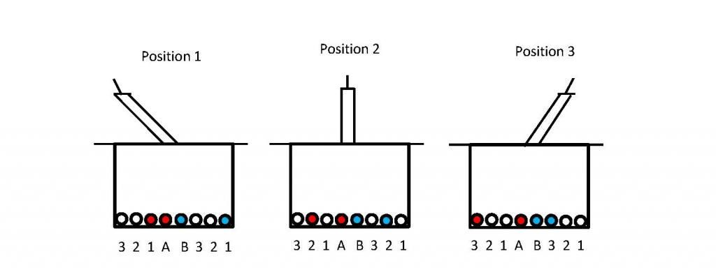 |
|
|
|
Post by sumgai on Aug 2, 2014 10:45:16 GMT -5
haydukej, Excellent craftsmanship!  Now, if only.... I, as an Administrator, cannot copy your excellent post elsewhere on the board, leaving it intact for this discussion. Instead I have the power only move it, and that's not desirable. Henceforth.... Will you please create a new post containing your new diagram in this thread: guitarnuts2.proboards.com/thread/3203/off-shore-lever-switchesThe reason I ask this is two-fold: a) We could've spent less time giving levant the info he needs by simply referring him to that particular thread. However; b) ChrisK's drawings are sometimes... obtuse, to be polite. He used a very intensive style of illustrating the mechanical workings of these switches, and that's more than most people are willing to wade through, just for the golden nugget of data they're seeking. Your drawing is concise and right on target, without all the mind-numbing jargon.  Thanks. sumgai |
|
levant
Rookie Solder Flinger
Posts: 6
Likes: 0
|
Post by levant on Aug 3, 2014 8:32:47 GMT -5
thanks for your answers, guys, especially you Newey. I mean I do appreciate the graphic schematic of haydukej too but that just confused me further. I just want to get this stuff wired and not having it blow up when I connect all the plugs eh lol
speaking of preamps in active pickups blowing up, what does cause that to happen? I remember reading somewhere that some guy forgot to replace his 9V battery on time and kept using it till it ran dry and that caused his preamp to break. I didn't own a pair of active pickups back then, so it just gave me mild chills then, but now that I'm about to install them in my own guitar, it quite frankly freaks me out a little.
What are general do's and don'ts with active pickups? Perhaps this belongs in another thread, in which case I apologize for asking that here. That's something I would really love to have experienced guitarists' opinions on. like the stereo and mono cables? I do have a stereo jack socket, it came with the set of pups, but what am I supposed to plug in there?a mono or a stereo cable? what would the effects of both be?
|
|
|
|
Post by newey on Aug 3, 2014 20:06:40 GMT -5
The stereo jack is usually used with active pickups/preamps to disconnect the battery when there is no cable plugged into the jack. This keeps the battery from running down when the guitar is in the case (or is otherwise not plugged in.). A regular mono cable is used, so that when plugged in, both the sleeve and ring connections are grounded. The battery negative is wired to the ring connection lug, so that when there's no cable plugged in, the battery (-) is disconnected.
I'm no expert on active pickups, I've never used them. But I can't imagine anything frying itself because of a low battery. I suspect that guy had his preamp break strictly by coincidence.
Think about a pedal with a 9V battery. The circuits used for most distortion-type effects are very similar to the preamp circuits in active pickups- and your pedals don't go "pffft" when the battery gets low, right?
If preamps are blowing up with regularity (and I'm unaware of this, but again, I don't use actives), I suspect poor quality components and/or excessive heat- heat is the enemy of all things electronic.
|
|
levant
Rookie Solder Flinger
Posts: 6
Likes: 0
|
Post by levant on Aug 5, 2014 4:45:22 GMT -5
right.. I did however have it go sizzle and smoke when I plugged in a 1000mA output power adapter to one.. twice(I forgot  ) So now I'm rather cautious about these things Again, thanks for your answers. |
|
|
|
Post by haydukej on Aug 5, 2014 16:52:35 GMT -5
Levant, I didn't get the impression that you ended up 100% sure on how to wire your guitar, but maybe I was mistaken. Anyways, I bastardized Tesla's drawing below to what I think will work for you as requested. Hopefully the weather will break for you.  |
|
levant
Rookie Solder Flinger
Posts: 6
Likes: 0
|
Post by levant on Aug 13, 2014 6:55:36 GMT -5
awh shite, that's perfect.. such a shame that I installed them yesterday without having a look at this(dont have home web access). I rushed looking at that switch pic alone as well, I ended up soldering only the leftmost and rightmost connectors. Now I'm going to have to connect 1 to 2 and 8 to 7. Thanks for the wishes on the weather thing, seems like the heat is passing, thank heaven. Oh, and I ended up making a 1 vol, 1 tone configuration - couldn't be bothered soldering another pot, my soldering iron is kind of retarded even though it's a 40W like recommended. And besides I figured the less cables and soldering blobs inside the less noise it should generate. Thanks for the modified pic, helps heaps Hope I did at least a moderately good job soldering all that. |
|


 , like a seesaw at a playground. If the lever is pointed towards "A", and "A" is towards the neck, the neck pickup gets wired to "B", and vice versa.


 )
)