|
|
Post by UlTiMaTe_L03 on Aug 5, 2014 2:38:07 GMT -5
Hi there this is my first post...please note ahead that ive spent nearlt a week on this issue and even bought an ebook for guitar wiring. I sent an email to a site owner and im going ri paste that below so I do not have to type it over but it explains my wiring dilema. I spent the last few days going through all your meterial and diagrams which has helped me understand so much about guitar wiring! I would your help as I used your meterial in my project. I have a 1959 vintage Crestwood Haweai Japanese model Epiphone 12 string. I have only found a few online anywhere and mine is unique in its own way that ive not seen ANY other guitar layout like it. I inherited it when my great grandmother passed and someone ripped out all of the wiring and I have to rewire 100% of it. I made a wire schematic for what I think is correct based on everything that ive found on your site but nothing works with the amp when I hook it up instead I only get sounds when I flip my switches on and off just a click noise. My layout is thus... I have 1 Volume and 1 Tone control...I have only 2 Single Coil Pickups and I have 1 DPDT Rythem/Solo Switch and I have 2 other DPDT switches 1 labeled MIC-1 and the other MIC-2. I attached a photo so you can see the guitar (im in the process of restoration so do not judge please). I also attached a png of my home made wire schematic (also please do not judge)...just a note for the schematic ignore all the diff wire colors I did it to better see what I was doing. Also all Black connections are the Ground connections the others are all the Hot connections. Please respond either way if you can or cannot help so I can know if I need to move on to other help. And...the blue boxes coming off the vol and tone pots are capacitors...I did not actually put the capacitor on the volume just the tone control already had one. If my diagram is wrong (I know it looks like crap) please tell me or direct me to a diagram that shows how to wire 3 DPDT switches witha solo switch and omly 2 pickups with 1 Vol and 1 tone pot...because I cannot find one Anywhere. also when im finished with my restoration ill post a link if you would like to see it. Here is my wire diagram and below is my guitar layout from the top side of my pickguard.   |
|
|
|
Post by newey on Aug 5, 2014 5:50:37 GMT -5
jtaylor330-
Hello and Welcome to G-Nutz2!
I gather there are two questions here: First, why doesn't it work? Second, is the wiring correct as it originally was?
As shown on the diagram, the cap on the volume pot is a problem as it shorts the output to ground. You say you didn't wire the cap on the volume pot (good- you don't need or want one there). But how did you in fact wire the volume control? The center lug should go to output and should not be grounded to the back of the pot.
As for the rest of the diagram, the wiring doesn't make much sense. As shown, P2 will always be "on" regardless of any switch positioning, and P1 will always be on as well, either "solo" (bypassed the V and T controls)if the solo switch is set one way, and with the controls if the solo switch is flipped. IOW, the solo switch is the only one that's actually switching anything.
So, I have any number of questions.
First, do you have a multimeter? I ask because any serious troubleshooting requires one, and also because you could have used one to check that the pickups were still operational before installing them. The pups on this thing are 50+ years old after all, and there was certainly a reason someone ripped all the wiring out of the guitar at some point.
Second, what is the basis of the diagram? Is there reason to believe that this is somewhat close to the original wiring, i.e., were you working from some other document or reference? Or did you just come up with the diagram on your own?
Without any other info, I would expect that the two other switches are individual pickup on-off switches. The "solo" switch might then operate on either the bridge pup alone, or on both pickups. But that's nowhere close to what the diagram shows.
Third, do you know whether these switches are "on-on" or "on-off" in configuration? Are they 2-position slide switches or three position? (I ask because the photo makes it appear that one is in a centered position). Again, if you don't know, a multimeter would tell the tale, and also allow you to know if they are all in working order.
Basically, with 50 year old components, everything should be checked before wiring it in. And, since this isn't going to be a museum piece (I assume the goal here is to play the thing, and not worry too much about its "classic value"), I wouldn't even bother to test the V and T pots, I'd just go ahead and replace them form the start. Even is they still work OK, after 50 years you can virtually guarantee they'll be scratchy/noisy in use- although a proper cleaning can help that sometimes.
|
|
|
|
Post by UlTiMaTe_L03 on Aug 5, 2014 9:36:21 GMT -5
I do have a multimeter and ill check the pickups as soon as I get home. I assume that im jost checking continuity. .. also, they are all 2 way on off slide switches.
I cannot find any original diagram for my model so I was going for the plan of P1 assigned to the Neck Pickup and always on and being able to turn P2 which was to be assigned to the bridge pickup and both off while the solo switch would bypass all other switches and pots so I did not have to change any Rythem settings while playing...I could not figure it out but I originally wanted to have the P1 switch assigned to both pickups on while the P2 switch turned on a phase reversal sound but I did not know if I could do that with the current switches and devises nor did I understand how to wire a switch like that and if I used both or 1 over the othe pickup etc... if this is possibe ould you explain it...Ill reply as soon as I know the pickups are good.
Oh, also, my volume pot is Center lug to output jack and from the diagram orientation the right lug is ground while the left is input from pickup switch, and minus the capacitor.
|
|
|
|
Post by UlTiMaTe_L03 on Aug 5, 2014 9:43:01 GMT -5
Oh another assumption or question, isnt an on/off switch the same as an On/On switch meaning that I can have a connection on both ends and whichever way the switch slides to will engage those lugs ? If no then I dont understand my switches simce they are. DPDT with 2 Poles as I understand and there are 6 lugs on each of them. Below is what my switches look like so I actually assume they are on/on switches...  |
|
|
|
Post by UlTiMaTe_L03 on Aug 5, 2014 10:48:22 GMT -5
Okay so ive done some teoubleshooting and re-drew my diagram. I want to say rwal quick that I read online that it not advisable for me to impliment a phase reversal switch because my pickup covers are metal and will cause high frequency noises and buzzing in my amp making it useless. So my new diagram puts Both of my pickups on the the mic1 switch at opposite ends allowing me to turn either one on so its an On/On swith setup and my mic2 switch has both pickups on the north Pole allowing me to engage Both at the same time when On (Which is most of the time) so its set up as an On/Off switch and those switches run to my Solo Rythem On/On switch where the South Poles are my Rythem and travel to my Volume Pot and Tone Pot where as my Solo North Pole is set to bypass and allow straight to Output jack. Is there any suggestion before I impliment this setup or something I may have missed here? Attachments:
|
|
|
|
Post by haydukej on Aug 5, 2014 13:24:17 GMT -5
...because my pickup covers are metal and will cause high frequency noises and buzzing in my amp making it useless. JT, you should check out Ashcatlt's works before calling high frequency and buzzing useless!  Okay, Disclaimer: My mind is very far from the most beautiful here. Translation, please let someone else on here vet everything below before going forward with it or even accepting it as truth. Nice job on your drawing; however, I think there are a couple flaws with it. 1) You show bass pickups (only 4 poles) being installed! Stupid joke, I know. 2) I'm not seeing a great benefit or function of "mic2" as you have it wired. Overall, I think the options below are what you are desiring, and thus what I attempted to draw even further below. - Neck pickup is always on
- A bridge pickup-on switch (Switch 1 (SW1): Either connects/disconnects the bridge pickup in series with the neck pickup.)
- Phase switching for when both pickups are on (Switch 2 (SW2): Phase (in/out) switch for the bridge pickup;) and
- A "solo"/"blower" switch which will bypass the volume/tone controls(Switch 3 (SW3))
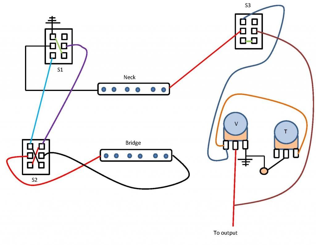 So, as I said, this is me attempting to get you those things. Hopefully it is not too far off! If it is, I will be jumping to the back of the class to learn with you. |
|
|
|
Post by JohnH on Aug 5, 2014 15:18:12 GMT -5
I like this guitar, it oozes fugly mojo, like many of us who were created at that time (well, there are some that just ooze...) and as an electric 12 string, it has extra appeal.
I'm not clear on what the switches are being intended to do here, or if we know what they originally used to do. But if none of that matters too much, and given that they are standard dpdt sliders, there is a lot of options that you could have, and you may as well have what you want.
If the pickups have two similar wires, neither of which connect to the metalwork, then series/parallel and phase options are all possible. first choice for me would be to use the two main switches for off/on with the pickups, but both up puts them both in series and both down has both in parallel, then the third switch for phase. Or the third switch could be the blower to bypass volume and tone. Or if series is not wanted, just use the two main switches for on/off, and when both are off, make that shunt the guitar output to ground to make it dead silent.
I like the positive feel of standard slide switches, and I use a couple on my LP, and they are what Brian May has been using all his life.
|
|
|
|
Post by UlTiMaTe_L03 on Aug 5, 2014 18:38:10 GMT -5
Hey all thanks and appreciation on my end. Im just glad you took the time to stop and consider my situation. Sorry for the pickup-=-Hickup in my drawing I didnt even realize it made a difference but my pickups have 6 screws or poles in them.
Thanks on the diagram too! See now, I didnt even know I coild run my ground wires out from a pickup to anything other than straight to a pot for ground...I suppose this is a part of in and out phasing pickups is using both wires with switches? I had 15 extra minutes so I implimented my latest drawing and ... the solo switch worked and I couldnt really tell wether or not my other 2 switches worked to switch on either pickup or together but.....I did learn....that all 3 o my switches Are bad *no surprise being as old as they are*, when I plug in my amp I got sound for a few moments of playing and then nothing at all...when I strum a chord and slight jiggle my switches I get a nice sound coming out and if im careful I can get the switch to hove in a sweet spot (On) and lightly play to keep from vibrating back out the connection.
I am picking up new switches although they will Fat head toggle switches still DPDT ON/ON to keep as original as possible and im going to impliment your drawing to see what I get with that phase reversal setup as my mic1 and mic2 setup didnt seem to actually yeild different results.
|
|
|
|
Post by UlTiMaTe_L03 on Aug 5, 2014 18:47:06 GMT -5
Oh, and this may be common assumption to most intermediate users, but am I safe to assume that im still going to ground my pots as they dont show ground wires in the diagram..also can you explain Why the ground wire go from pickups to the switches and why switch S1 has a ground out on the 1st pole? Im just wanting o better understanding why its setup that way to get your described result.
|
|
|
|
Post by UlTiMaTe_L03 on Aug 5, 2014 19:10:48 GMT -5
haydukej I am considering (waiting for it in the mail) putting in a 3rd single coil pickup as a middle pickup. Is there a fast explanation as to how that would work for your diagram or would it require an entire new drawing. I understand with a 3rd pickup my range of sounds greatly increases but unless you (any of you) have 3 pickup setups that you just cant live without recommending them (haha just kidding please recommend away) I would kep a simmilar setup and go with the phase reversal as I still want to see what sounds I get spilling out of this golden oldy.
|
|
|
|
Post by newey on Aug 5, 2014 22:32:38 GMT -5
OK, there's a lot of stuff flying around here, so I think we need to zero in on exactly what you want before we get into a "dueling diagrams" situation.
Haydukej's diagram will work as advertised.
But let's try to condense things down:
Yes, Haydukej omitted those grounds for clarity on the diagram, they are understood to be needed in all cases. Whether the backs of the pots are used for the purpose is a matter of preference, but you do need somewhere to collect all the grounds.
Hduke 's diagram has the two pickups, when the bridge is added to the neck via S1, wired together in series instead of in parallel. That's why the bridge ground goes to the switch, so it can be linked to the neck pickup in series. S2 is the phase switch on the bridge pickup; this simply flips the + and - around before the signal goes on to S2. The solo switch bypasses the controls in all settings of S1 and S2.
To each their own, of course, and it's your guitar. But I can't see how a set-up where the neck pickup is always on is advantageous. I can't imagine living without being able to select either pickup by itself in a two-pickup guitar.
Series wiring of two single coil pickups is similar to the Brian May wiring, but also to some old Japanese Teiscos and a few other "oddballs". It's a matter of preference, the series wiring will be a bit "beefier" and full-sounding, with more bass. A similar scheme using parallel wiring can also be done if desired.
It would require a new drawing at the very least, but probably will require more switching as well. You need to have some way to turn it on and off, presumably.
How is it keeping it original to replace the slide switches with toggles? What about the square cut-outs for the slide switches?
Since we don't really know what the original wiring is/was, it seems to me that you should implement it how you want it. One idea, since you have to buy new switches anyway, is to replace the On-On sliders with 3-position On-On-On sliders (these will have 8 lugs instead of 6, but can be found in the same form factor and will bolt right into the existing mounting slots)
Using the 3-way On-On-On switches can allow you to have each pickup switchable between on/off/phase, all on one switch, similar to the wiring on the classic Fender Mustang guitars.
|
|
|
|
Post by haydukej on Aug 5, 2014 23:25:30 GMT -5
Series wiring of two single coil pickups is similar to the Brian May wiring, but also to some old Japanese Teiscos and a few other "oddballs". It's a matter of preference, the series wiring will be a bit "beefier" and full-sounding, with more bass. A similar scheme using parallel wiring can also be done if desired. JT, if I can expand a bit on the above. I chose to have the pickups wired together in Series (instead of Parallel like a typical Strat/Tele single coil configuration) based on your initial desire of having phase reversal. As Newey states, to each his own, but it is somewhat common belief around here that when implementing phase switching, Series Out of Phase (SOoP) is more desirable than Parallel Out of Phase (POoP). POoP tends to be very thin sounding. Your enthusiasm to mod seems unbridled at the moment. If you're not familiar with the Series and SOoP sounds, I'd say go ahead and wire it up as I laid it out (since Newey approved it) and play with those tones for awhile. Find out what you like and don't like about the layout/tones. Then ask yourself again what tones do you think you're missing? And, how close to "original" are you wanting this guitar to stay? JohnH and Newey gave some good ideas for going forward. |
|
|
|
Post by UlTiMaTe_L03 on Aug 5, 2014 23:58:00 GMT -5
I will definitely think a while on this setup. I will go ahead with your design as I like the sounds ive found others perform with out of phase. Like you said ill try it for a while before making other changes. Newey, im ordering a new pickgaurd for this and also a new bridge, tuning keys, pickups, switches pots etc the whole guitsr needs restored from the hardware to the electrical. For some reason I stumbled arross these fat head 2 way toggle switches below, and really liked them but now im going to consider what you said abiut the 3 way switches and the fact that toggle switches can be broken easily. I will take all this into consideration and be playing with the current wire diagram as above and ill respond if I have any more issues or conclusions. www.radioshack.com/product/index.jsp?productId=2062513# |
|
|
|
Post by newey on Aug 6, 2014 5:43:41 GMT -5
jt-
I wouldn't buy that switch sight unseen from RS. The web link has virtually no info, and in particular doesn't show the back of the switch, so you can see what type of terminals it has (they could be screw-on, not solder lugs which is what you need.) It also doesn't give any dimensions, but it appears to be a fairly large-bodied unit likely meant for automotive use. Two of these mounted side-by-side may present fitment issues in the guitar cavity.
If you're going to mail order stuff like switches, you can get a better selection, at a lower price, from an electronics jobber like Mouser or DigiKey. Their websites will also link to the manufacturer's data sheets which have exact dimensions. This is particularly important if you're going to replace the existing slide switches with new ones, as sizes vary. There are lots of types of switches at these places, so pay attention to the type of mounting, sizes, lugs, etc.
If you really like the flat black toggle style, they have those as well. Be aware that, when a switch description uses parentheses (e.g., "(On)-Off" instead of "On-Off"), the parens designate a switch with momentary actuation, which is not what you want.
Toggle switches are much easier to mount if you're starting from a blank pickguard, as it's easy to drill round holes compared to cutting a square opening for the slider. We were speaking of keeping things fairly original, but it now sounds as if that's not really a priority.
Toggle switches are also easier to "switch on the fly" onstage, while the sliders are a bit more "fiddle-y". OTOH, if the switches are going to be mounted as the switches were originally on this guitar, (i.e., above the strings when held in playing position), then sliders are a better option as they aren't in the way as much as a toggle would be.
Toggles are also available in 3-way On-On-On configuration, as well as On-Off-On.
If you're going to add a third pickup, and since you're replacing the pickguard as well, it's easy enough to add another switch to control the mid pup.
To answer an earlier question, On-Off switches are different from On-On types, and the two types are not interchangeable in guitar wiring. Ordinarily, 6 lugs would imply a two-pole On-On configuration, but you can't always go by that as some manufacturers will use the same switch body and lugs for both types, even though the On-Off type doesn't use the extra 2 lugs. (the added cost of the extra unneeded bits is more than offset for the manufacturer by simplifying of the stock of parts and simplifying production- they just use the same switch body and lugs for everything, and only the internals changes.
Given that you have a meter, test all components to be sure prior to installing. In order to get an accurate reading, the resistance of the pickups should be checked before they are wired to anything, likewise with other components. Keep a log of the pickup's values, those numbers will be valuable info if any troubleshooting is needed later.
|
|
|
|
Post by JohnH on Aug 6, 2014 16:24:25 GMT -5
Just wanted to express an opinion, to replace whats bust but try to work with the current look, ie pickguard, switch type, bridge etc. A third pickup will stick out like a sore thumb. Theres few enough guitars of that age left in the world, and plenty of cheap strats that make good project guitars.
|
|
|
|
Post by UlTiMaTe_L03 on Aug 6, 2014 16:36:04 GMT -5
JohnH I do value your opinion and I think after everyones comments I am going to keep the original look im just trying to find the correct size switches now. Mouser seems to have a great selection. Im custom ordering a new pickguard with an exact tracing of the original and cutouts for pots , pickups and switches. The only non orignal part I have to change (except pickguard) is the 12 string bridge, and I still have the original bridge cover so you wont notice. I have to change it because the current spacing of the strings is about 1/16th to wide on both ends making the strings sit over the edge of the fretboard from frets 13 and up. So just getting a more narrow spacer for the strings which is just going to be this.  *Edit...not sure why but ive had trouble posting Images so sorry.
|
|
|
|
Post by UlTiMaTe_L03 on Aug 7, 2014 22:37:39 GMT -5
Can you explain why I get a loud buzzing with my amp (clean chanel no distortion or OD) when im not touching my guitar? If I touch anywhere from my strings to my tuning keys or my bridge/pickguard the buzzing stops, and this doesnt happen with any of my other guitars. I thought maybe something wrong with the grounding but ive triple checked all my wiring and grounds and the connections are flawless from what I can see.
|
|
|
|
Post by newey on Aug 8, 2014 5:50:13 GMT -5
Check to see that you haven't accidentally reversed the connections at the output jack.
The strings should be grounded, via a wire from under the bridge to the grounding point (the back of the pot as shown on your diagram). The fact that it gets quieter when you touch the strings is an indication that there is such a ground in place, but check it anyway.
You spoke of replacing the pickguard. The old one was apparently metal, and the bridge may thus have been grounded through the metal of the pickguard, by contact. If you replaced it with a non-metal one, you may need to run a ground wire from the bridge if there wasn't one originally.
|
|
|
|
Post by UlTiMaTe_L03 on Aug 8, 2014 21:13:41 GMT -5
If I remove the bridge there is a Ground wire underneath of it running through a hole and to the Output Jack. The only thing is that the bridge is just sitting on top of the ground wire and it is not actually connected. I am considering just pulling more wire out so I can reach the backside of the bridge and solder it directly to it so there is a definite connection. I also picked up 3 new Slide witches this morning to replace the bad ones so we will see how it all works out later on today.
|
|
|
|
Post by UlTiMaTe_L03 on Aug 9, 2014 12:38:50 GMT -5
haydukej Well I put in my new switches and rewired according to your diagram but Sw1 (When Turned On ^Up) mutes all sound. I dont even hear the Pickup thats supposed to always be on. I am opening it up again ( I really wish there were cavites in the back of this cause removing these strings over and over sucks ha) and im gonna look at everything and draw a diagram.based on what I see and compare to yours to make sure I did it correctly. newey Also my buzzing noise issue did not recess any :/. Im replacing the Pots and putting in new pickups soon so hopefully that will fix the issue.
|
|
|
|
Post by UlTiMaTe_L03 on Aug 9, 2014 13:54:01 GMT -5
haydukej I drew my current wire diagram and it matches yours identically so I do not know why Sw1 kills all sounds when turned On apparently my pickup isnt always and maybe bad , although I checked with a meter and didnt find issues. :/ I dont know.
|
|
|
|
Post by haydukej on Aug 9, 2014 15:10:22 GMT -5
JT, Now the fun part of modifying your guitar...the troubleshooting. I honestly did not imagine my diagram would be correct on the first draft, but if Newey stated it should function, I am tempted to say one of your components is suspect. With that's said, let's try to pin down the problem child. Pre-test notes: As we know it can be a pain restringing your guitar each time for trouble shooting. To test if your getting output from a pickup, (make sure your volume isn't cranked to 11 in doing this) you can GENTLY lay a screw driver across the poles of your pickup and then remove it. Doing this should make a popping sound from your amp. Also, do a review of all your solder joints and wires. Are you confident in your soldering skills? 1) If I understand your previous statements, with SW 1 in the "off" position you do get sound, correct? If yes, then what about when you turn "on" the SW 3 (blower) switch, do you hear a change in tone then (i.e. with this switch on, does moving the Volume/tone make any difference?) While we're at it, with SW 3 (blower) off, do your Volume/tone pots function properly? 2) Do you know the resistance of your neck pickup? If not, use your multimeter to measure it by connecting it to the positive and negative wires of your neck pickup. Now, turn on SW 1. Keeping the positive multimeter lead in the same place, move the negative lead to the bottom lug of SW 1 (where the blue wire is coming out on the diagram). Are you getting the same number here? 3) Again, keeping SW 1 "on" and the positive multimeter in the same place, move the negative lead to the lug where the purple wire connects to SW1. What's that number? Keeping everything the same, turn "on" or "off" SW 2 (phase switch), how does that change the number? 3) To test if SW2 is properly reversing the phase of you pickup, you can try JohnH's Phase Screw Driver Test. If we get those multimeter numbers, that should help track down what might be the issue. Other members on here might have better ideas, but that's how I'd approach it. Hope that's straight forward. |
|
|
|
Post by UlTiMaTe_L03 on Aug 9, 2014 16:52:24 GMT -5
I will get these answered as soon as I can. I also want to note, like before , all the wiring was out when I first got into it. Including the wiring on the pickups themselves so I opened them up and soldered new wires onto them, the only issue was that both wires were black and I replaced with color coded red and black but I do not know which side was the ground just a 50/50 shot really.
|
|
|
|
Post by newey on Aug 10, 2014 18:15:02 GMT -5
It should work either way around, the only issue is that it may be out of phase with the other pickup. But flipping the phase switch should take care of that anyway.
More to the point, those new connections should be double-checked. Also, as haydukej notes, please give us an output reading for that pickup, and answer the other questions raised as well. We'll help get this sorted.
|
|