vhgtar00
Apprentice Shielder

Posts: 28 
Likes: 0
|
Post by vhgtar00 on Oct 4, 2014 23:21:14 GMT -5
Hi, I'm new to the community. I have a challenge for any wiring expert who can help me out. I've recently come across a cheap guitar that I'd like to rewire. Having little experience in wiring electronics and no experience in designing circuits, I need some help with an unorthodox, slightly ambitious design I came up with. This design is kind of like Jimmy Page Wiring but with 3 pots and a 5 way switch as these are the constraints I have to work with. Also, as a note the guitar has two four-wire Seymour Duncan Humbuckers in it. Specs: 5 Way Pickup Selector Settings: 1) Neck 2) Neck + Bridge (Parallel) 3) Neck + Bridge (Series) 4) Bridge 5) No output (Killswitch) Potentiometers: Neck (Top Knob) Bridge (Bottom Knob) Volume: 500k Audio Taper Concentric Push/Pull Pull Effect: Neck and Bridge Pickups out of phase with each other Neck Pickup Tone: 500k Audio Taper Push/Pull Pull Effect: Splits Neck pickup Bridge Pickup Tone: 500k Audio Taper Push/Pull Pull Effect: Splits Bridge pickup Additional Mods: Treble Bleed, '50s Vintage Wiring I will be gathering the parts soon. I would appreciate any guidance in helping me wire this up. A link to a JP Wiring Diagram for reference: www.guitarelectronics.com/media/img/guitarelectronics/W650-H650-Bffffff/W/wd2hh3t22_09jp.jpg |
|
|
|
Post by JohnH on Oct 5, 2014 0:06:02 GMT -5
Hi vhgtar00 and welcome to GN2
What you suggest is quite possible, but so that you can get suitable parts, I believe the 5 way switch will need to be a four-poles super-switch type, rather than a standard 5 way.
Also, the spec was all good until the bit about the 50's wiring (meaning tone controls after volume). A lot of people swear by this, and good luck to them. But in the arrangement you describe with two tones and one volume, it will complicate the wiring and result in missing out on some interesting possibilities with the two tone pots. Treble bleed will sort out the clarity of tone at lower volume and with 500k pots, it is best as a 150k resistor in parallel with a 1nF (= 0.001uF) cap.
|
|
|
|
Post by sumgai on Oct 5, 2014 16:29:28 GMT -5
vh, Hi, and welcome to The NutzHouse!  As John said, but he did miss a point, to wit: '50s Vintage wiring requires that the Tone pot come after the Vol pot, as the signal travels from the pickup to the amp. However, that pretty much requires that for each pickup, there must be a separate Vol pot. In your scenario, putting both pickups on one "master" Vol pot precludes using a separate Tone pot for each pickup - they've already been combined at the input to the Vol pot. (Actually, the combining took place at the selector switch.) This says to me that, as properly noted by John (check his research on this topic, there's a "sticky" thread labeled Vintage Tone Controls, a little ways above this thread), so-called vintage tone wiring will not be your first concern... whether or not to replace the Volume control with a concentric dual pot will be the decisive factor. Without that dual-pot, your idea won't get very far along, sorry to say. While we Nutz often tend to get all "nutzy", we also feel for beginners that don't want to go nearly so far. Indeed, sometimes the beauty of a well-designed mod is that it's what we call 'stealthy' - the axe looks stock, but the Tones it produces are completely different from the usual stuff. In your case, I'll assume that you wish to maintain a stock look. Fine.... all you need to do is obtain a concentric dual pot, with both halves having the same value. Wiring-wise, you're going to treat it as if it were two separate controls - electrically they're separate, but physically they have one shaft inside of the other. The only "give-away" is that there are two knobs (one smaller than the other) where you'd expect to see only one knob. This one modification will open up a whole world of potential Jimmy Page-like mods, as can be seen in our sub-forums - several different threads abound therein. (And not a few of them from JohnH himself.  ) Outside of that particular part replacement, you're going to have to live with either two Tone controls (one per pup) coming before the Vol pot, or else use one of them as a Master Tone after the Volume, ala Vintage Wiring. Then you'd use the other pot for something like blending one pup into the other (another of John's favorite Tone-tricks, but much loved by others here), or replacing it entirely with a rotary switch. That kind of switch opens up a lot of possibilities, and with a pair of humbuckers, it might be something to consider. Let me also insert a personal preference here: I'm not a fan of putting a "kill" switch on the same control as other functions. When performing on stage (meaning, in front of people), and you want to switch to a different tone, it's altogether too easy to flick past the intended stopping point, and hit the SILENCE position - that's embarrassing, to say the least. Moreover, what if you wanted to "stutter" between the Silent position and what's not the next position in line? (For example, pos 4 is Bridge, and pos 5 is Silent - but you want to stutter with the Neck and Bridge together, presumably in pos 2?) Not only is that gonna be difficult, but most any 5-way switch is not gonna take that kind of abuse for very long, I'm here to tell ya. In essence, if you're gonna use a Master Tone (Vintage-wired or standard), then you could replace the pot in the third hole with a momentary kill switch, usually a push button (spring loaded up for 'sound is on' - you push it down for silence... removing your finger automatically restores the sound output). If you want a toggle switch, that can have a center position where sound is on, but one side is spring loaded - flick it for silence, and let go... it returns to center position and sound is back on. The other position would not be spring loaded - it stays silent until you manually restore the handle to center. That's good for silence when you set your guitar down for a break or something. But of course, it's all your call - have fun! HTH sumgai |
|
|
|
Post by newey on Oct 5, 2014 21:13:47 GMT -5
JohnH and sg-
I think you both missed the part where vhgtar00 said:
As far I am aware, no such part exists. Rune had that dual gang P/P a while back, but I've never seen a concentric pot with a P/P switch. So, something from vhg's wishlist will have to go by the wayside.
I'm with sg on putting the kill switch on the 5-way- too tough to switch it on/off. If a phase sound is wanted, and given that a Superswitch will be needed anyway, the OOP sound could be put on the 5-way (best would be if it were series OOP),and the killswitch relegated to a separate switch.
|
|
|
|
Post by sumgai on Oct 6, 2014 0:01:48 GMT -5
newey, I knew such a thing didn't exist, so I just summarily dismissed it from my mind... then I went about replying, leading myself back into nearly the same part (meaning, minus the p-p switch). That's what I get for not reviewing the original question several times, as I proof-read my own drivel.  And looking back, I don't see that John missed the specification, his reply pretty much assumes that there are two pots, which implies that he "got it" about the concentric dual pot. At least it appears that way to me. vh, Sorry for the confusion, I'll take the hit for that one.  But if you're gonna use one concentric dual pot for the Vol, why not a second for the Tone controls, too? Then you'd replace the third pot with that spring loaded pushbutton switch I mentioned earlier, for the Kill function. (Or the 3 position (one momentary) toggle switch, depending on your needs/wants.) Still want OoP? No problem! That goes in the 5th position of the 5-way selector switch. (Discussion: most players don't like OoP for Parallel, only in Series, so 5 positions should be satisfactory. But you're still gonna need to obtain a SuperSwitch to get all of these options.) HTH sumgai |
|
|
|
Post by JohnH on Oct 6, 2014 1:26:11 GMT -5
Its a good call to put the series OoP on the 5 way super-switch. If there are dual volumes, then all of that has to be before the five way. Each of neck and bridge has a module, comprising the pickup coils, the coil cutting, tone and volume pot, out of which 2 wires go to the 5 way to get selected or combined. Its a bit like this design, on which I based my own LP: LP modular wiringsee switching module 6, which was the 5 way selector. I did it with two slide switches however, and also, the coil cutting was just by turning the tone pot to 10 (at 9 and below it is humbucker). This worked well and I've had it like that for a few years now. But, for this thread, there could be separate tone pots, each with a p/p switch to cut to single for its own pickup. A dual-concentric volume pot, no switch on it, and a 5 way superswitch. (Id be tempted to strip it back further though, to no pp switches at all, just the coil cut by the control position, and a single volume pot at the output.) |
|
vhgtar00
Apprentice Shielder
Posts: 28
Likes: 0
|
Post by vhgtar00 on Oct 6, 2014 18:09:41 GMT -5
So after reading JohnH's post, I decided to take a second and rethink my wiring setup. I think I've found a better solution for my needs. What do you guys think? --- Specs: 3 Way Pickup Selector (Unless there are any ideas for additional settings with a 5-way) 1) Neck 2) Neck + Bridge 3) Bridge Potientiometers: (3) 500k Audio Taper Concentric/Dual Gang Push/Pull Pot. #1: Volume Top Knob: Neck Volume Bottom Knob: Bridge Volume Pull Effect: Reverse Neck Phase Pot. #2: Tone Top Knob: Neck Tone Bottom Knob: Bridge Tone Pull Effect: Reverse Bridge Phase Pot. #3: Spin-A-Split Top Knob: Blends in bridge-side Neck coil Bottom Knob: Blends in bridge-side Bridge coil Switch, Toggle, 3 Way Switch: Kill Volume Additional Mods: Treble Bleed --- After brainstorming this stuff, I looked towards the flood of new messages the thread got (thanks by the way!) and reflected a little bit more. 50's Vintage Wiring I have no problem letting go of this idea. It was recommended to me as 'something better' so I decided I would try it. However, I didn't really understand the implications and would not like to over complicate my wiring setup, so maybe it would be a good thing to try *after* I get everything working. Or maybe not... Stock Look No offense, but I laughed so hard at that when I read that. Reason being is this Cheapo Squire guitar's black paint job was stripped by me and a friend which left it with a pretty unique 'finish' that certainly looks like no other guitar I've ever seen. It's grungy and crappy looking, but in an interesting kind of way. Maybe I'll show a pic sometime soon. The only reason I don't want to add any other pots is because I think they would fit awkwardly on the pickguard, but adding a small kill switch would fit fine. Concentric/Dual Gang Push Pull Potentiometers I thought the Concentric Push Pull was very rare and I searched many (terribly designed) industrial company website catalogs for them with no luck. After awhile, I stopped using 'concentric' as my search term and started using 'dual gang'. I immediately found tons of those Concentric/Dual Gang P/P pots and am now looking to use more on my guitar. I think they're really neat and efficient for the space they take up on the pickguard. Kill Switch I recently bought a standard On/Off switch for the guitar and read this... now I'm going to return it so I can get this 3 way spring loaded switch. I was trying to figure out how I could do both momentary and standard but just compromised on the standard. Now I don't have to!  --- A few final questions... - What kind of Capacitors do you guys recommend I use? I figure I'll buy the best recommended and try them all out.
- Are there any Nutz ideas out there for the other two free options for my pickup selector? I have a standard five way and don't really see any point in downgrading. If the ideas are good enough, I'd rather buy a Superswitch.
- Where should I look to learn about wiring guitar electronics components? I'm trying to get an understanding of exactly how to wire the Pots, Switches and Capacitors to create my circuit (or learn enough to improve it). I know there are probably resources on this Forum, but I'd appreciate it if someone could share a link. I've haven't got time for anything as of recently.
Thanks guys!
Sincerely,
vhgtar00
|
|
|
|
Post by newey on Oct 6, 2014 22:11:24 GMT -5
VHG- As I mentioned, we've had designs using a P/P pot with dual-gang pots. But a Dual-gang concentric pot is another animal entirely. If you have found such an animal, great! Please post a link so I can order some . . . A dual gang P/P will allow you to wire the two volumes and the 2 tones independently- you just can't control them independently. Unlike a concentric pot with its "nesting knobs", a dual gang pot is simply two potentiometer elements controlled by a single shaft (and knob). Don't spend money on fancy capacitors. I use the green "chicklet" -style polyethylene caps, they're cheap and reliable. Spending more money won't get you better tone, it will (at best) get you a lower range of tolerances and sturdier construction. But the tolerances don't really mean much in a real world setting, and your guitar isn't stressing the caps, so sturdiness/reliability isn't a big issue either. Yes, numerous possibilities. More discussion on this will no doubt follow. Check our reference section, there are a number of links to more or less detailed basic electronics materials Reversing the phase on both pickups is redundant and doesn't add any additional sounds- bridge OOP with the neck pickup is exactly like neck OOP with bridge. Reverse both and you're right back to where you started- both are in phase again. So, no need for separate phase switches, just pick one on which to reverse the phase, doesn't matter which one. Thus, you can save one Push/Pull for other duties (again, assuming what you want exists in the first place) |
|
|
|
Post by haydukej on Oct 6, 2014 22:34:46 GMT -5
Edit Newey beat me to it, but I'll be damned if he takes my 100th post away! On a side note, has anyone vetted these yet? Details are sketchy, but it does have the terms "concentric" and "push/pull"? Concentric/Dual Gang Push Pull Potentiometers I thought the Concentric Push Pull was very rare and I searched many (terribly designed) industrial company website catalogs for them with no luck. After awhile, I stopped using 'concentric' as my search term and started using 'dual gang'. I immediately found tons of those Concentric/Dual Gang P/P pots and am now looking to use more on my guitar. VHGTr - I think you might be under the false assumption that concentric and dual-ganged are interchangeable terms. While both types (concentric pots & dual-ganged pots) are essentially two pots in the space of one, a concentric pot will have two separate shafts while a dual-ganged pot has only a common shaft. If by chance you did find a concentric p/p, please share a link for the rest of us to view. A few final questions... I believe around this forum you'll find the general consensus that capacitance is capacitance (i.e. polyester film, ceramic, etc.) Don't buy into the $25 vintage paper oil bumblebees.
|
|
|
|
Post by haydukej on Oct 6, 2014 22:50:19 GMT -5
Looks like our Denmark friends (Warwick) and MEC might have some options of the concentric P/P too. 25K 100K DPDTMain page |
|
|
|
Post by newey on Oct 7, 2014 4:59:06 GMT -5
haydukej's first link - "has anyone vetted these yet?" is for a concentric stereo P/P pot. This has a center detent and is meant for use as a balance control. It might suffice for use as a blend pot, but I don't think it's what vhg wants. Also, it's only a 50K value, which might work with an active set-up but isn't a good value for passive pickups. The description also doesn't give a shaft diameter, but it looks tiny, hard to say if a std knob would fit it. For connections, it has pins for wiring to a PC board, which is its intended use. While those can be soldered directly, it's a lot trickier to do than ones with regular solder lugs.
The links to Warwick and MEC are also to PC pin style ones with varying values, I didn't see any with both pots at 250K or 500K. And 50+ Euros for a pot? I have whole guitars that aren't worth 50 Euros . . .
|
|
vhgtar00
Apprentice Shielder
Posts: 28
Likes: 0
|
Post by vhgtar00 on Oct 7, 2014 8:59:30 GMT -5
Potentiometers
So I knew there were expensive concentric & push pull pots out there but I thought I found some that were bargain-priced. Unfortunately they weren't actually concentric and push pull; I was excited and didn't think clearly. I don't think I'm going to pay that much of a premium for Concentric P/P pots, so I should just stick with a rotary switch or something.
You're dead on, thanks for the clarification.
Yeah, definitely out of the budget. I can make do with cheaper parts. That's for sure.
Phase and Polarity
I understand what you're talking about now. I didn't have a great understanding of phase and of polarity, which is what I was actually thinking of doing. The thought in my mind is if I switched a pickup's polarity, I'd get a different tone but I learned if I switched the pickup selector to both pickups, the pickups would cancel each other out. That's not something I'm interested in doing so I'll stick with phasing option alone.
---
I'm going to have to rethink this whole circuit again. I like the idea of having concentric pots for Volume, Tone and Blend on each pickup. I also want the ability to use both pickups phased and in parallel so I think I'll add a rotary switch for that. I'll also be adding a spring-loaded switch in the guitar for momentary and toggled kill.
I don't like sounding like an idiot like I have for some time now, but I suppose every mistake I make is an opportunity for learning and trust me, I've learned a lot so far.
Any interesting suggestions? Let me know.
Thank You,
vhgtar00
|
|
|
|
Post by newey on Oct 7, 2014 16:18:34 GMT -5
We all started somewhere. You're certainly less of "an idiot" that I was before I jumped into this stuff. No worries.  That's the appropriate attitude to have. I'm not sure you are quite getting it yet. AC circuits, like those in your guitar, have a property called "phase". This is a simplification, but think of it like 2 sine waves, as on an oscilloscope. If the peaks and valleys of both waves match up, the two are "in phase". If the peaks of one wave occur when the other wave has a valley, they're out of phase. "Polarity" is a term that refers to DC circuits, which have a - and a +. It also applies to magnets, which have poles designated as "North" and "South". Polarity is important in guitars only when we talk about the magnets in our (magnetic) pickups. If you put two pickups "out-of-phase" with each other (by definition, a pickup can only be "out-of-phase" with reference to another pickup, it can't be "OOP" all by itself), the signals of the two will cancel each other to some extent. If the two signals were identical, the signals would cancel entirely, and you would hear nothing. But pickups differ, even when of the same brand and model, and they are placed at different positions along the string, meaning they reproduce the string's vibrations differently. So, you get some of the sounds from each one that don't cancel out, and you get an "out-of-phase" tone, which some people like. Anyway, here's some homework for you, so that you can better "zero in" on what you want to do here. How to explain hum-cancellingBlend and Pan potsLever switches Explained5-way switch lugs |
|
vhgtar00
Apprentice Shielder
Posts: 28
Likes: 0
|
Post by vhgtar00 on Oct 7, 2014 20:51:57 GMT -5
So I went ahead and simplified the things I wanted to do by what type of electronic component I needed to do it in order to create an action plan. Potentiometer Control- Neck Volume
- Bridge Volume
- Neck Tone
- Bridge Tone
- Neck Blend
- Bridge Blend
Switch Control- Swap neck coil being blended
- Swap bridge coil being blended
- Pickups out of phase
- Pickups in series
- Volume Kill
Now to implement all of these things I would need six potentiometers and five swiches (not including pickup selection options on my Five Way Superswitch). PotentiometersTo decrease the amount of potentiometers I would need on the guitar, I will be making the Two Volumes and Two Tones work on concentric potentiometers. I will add another hole in my pick guard to allow for two P/P potentiometers that will control Neck and Bridge blend. SwitchesI have five controls on this guitar that require switching. To save on space, I will include the Phasing option in my 5 Way Superswitch. The coil-blend switches will be implemented on their respective Blend P/P pots. Volume Kill will have its own dedicated Center On Toggle & Spring-Loaded, Momentary Off switch. My problem with the switches comes down to the last remaining option: Pickups in Series and the implications of it. Let's say I have these options wired in on my Superswitch: Neck / Neck + Bridge out of Phase / Neck + Bridge / Neck + Bridge in Series / BridgeIf I happened to pass through Series mode on my way from the Neck selection to the Bridge selection, I would get a burst of Volume/Gain in my output. For that reason, I don't know if its advisable to wire Series like that (especially on a high gain setting, although that isn't necessarily my thing). Should I put it on its own independent toggle switch? If I do that, then I'll have one option open on my Five Way and no other ideas to fill the void. I'd rather not make a redundant position in my Five Way switch and I don't want to look for the only 'Four Way' Superswitch on the market so my remaining options to fill the void are to make that last setting a toggle kill (thus I'd convert the Volume Kill switch above to a momentary switch) or to find another wiring combination. So without further ado, any suggestions for that final setting? I cannot really fathom another way I could increase the versatility of this setup, given my limited experience and knowledge of electronics mods. I'm open to anything as long as its not diabolically challenging to do. Thanks Guys, vhgtar00 Neck / Neck + Bridge out of Phase / Neck + Bridge / < Open Option > / Bridge |
|
|
|
Post by newey on Oct 7, 2014 22:44:55 GMT -5
First of all, a word on nomenclature. None of this is written in concrete, but as a matter of convention and easy of understanding, we tend to use the "+" sign to indicate a parallel connection and an "x" (or a *) to indicate a series connection. So that we're clear on what you want, it's:
neck/N * Br OOP/ N + Br/N * Br/Bridge
with the possibility that the N * Br might be substituted for something else. (I assumed the OOP setting would be series out-of-phase ("SOOP") rather than POOP.)
So, a couple of suggestions. First, if the reluctance to put the N * Br on the superswitch is the level increase with series, I frankly don't know how big of an issue that really will be. But if you feel it's a concern, there are a couple of options.
A Superswitch allows you to have any of your desired combos at any position you choose, so one solution is to move the series setting to the end. Say, like this:
N/N + Br/ Br/N * Br OOP/N * Br
This seems a bit funky at first, but think about it. You've essentially made your 5-way into a "3 + 2". Positions 1, 2 and 3 are just like on a three-way toggle, a la LP or SG:
N/Both(in parallel)/Br
Then, you have the two series options at the end, with the (lower output) OOP option coming next at P4, and the full series at P5. Switching may seem a bit weird at first, but I find that I get used to switching order with a few hours of playing.
Another option is to take the series setting off of the 5-way switch (as you propose to do) and put it on a separate switch (which could be one of the P/Ps.) This would be set up to bypass the 5-way entirely, so that actuating it puts N in series with the Br (i.e., N * Br) regardless of where the 5-way is set. This has a couple of advantages. First, one switch flip or pull can give you the full series HBs no matter what your previous 5-way setting was, which could be useful for a solo blast. But more than that, you could also bypass the 2 blend pots when in series mode. Blend pots in series can be problematic; to do that right, the blender(s) need to be able to be switched between series operation and parallel.
Although, I think we need some clarification on the blend pots. Just what is being blended with what? Are we blending, for example, one neck coil with the other neck coil? Or is the N being blended with the Br?
Another option to simplify things would be to use the two tone pots to split the coils, as JohnH has often done and advocates for.
As far as other options to go on the 5-way switch, a so-called "half out-of-phase" ("HOOP")setting would be a popular way to go. This will be quite different from a regular OOP setting. Or, you can leave the two pickups in phase, but bleed some of the signal from one of the two via a cap, as is done in the half OOP setup.
|
|
vhgtar00
Apprentice Shielder
Posts: 28
Likes: 0
|
Post by vhgtar00 on Oct 10, 2014 17:07:15 GMT -5
Now that I know the proper conventions, let me restate what I had in mind for my previous pickup selector options: N / N + Br OOP / N + Br / N * Br / BrI don't understand Blending but what I do know is that I don't want to do it anymore. I'd rather have a volume control for each coil on my two humbuckers. Volume is something I (as well as my close friend whom I also let play the guitar) understand... blending is not. As I'm told, it is apparently easier to make more accurate adjustments with two volume controls than with a single blending pot. I can fit the two volume controls in my pickguard under a single concentric pot so the solution works for me. This actually greatly enhances my spec. because I can now eliminate two redundant Switch Controls. I'll re-update my previous action-plan below: Potentiometer Controls- Neck Coil #1 Volume
- Neck Coil #2 Volume
- Bridge Coil #1 Volume
- Bridge Coil #2 Volume
- Neck Tone
- Bridge Tone
Switch Controls
With the redundant switch controls out of the way, I now can utilize their P/P's and get rid of the pickup-switching fiasco I had on my hands.
Here's how the circuit should now work:
Pickup Selector Switch Settings: N / N + Br / Br
Potentiometers:
Neck Pickup Volume Control (Concentric)
Top Knob: Controls neck-side coil volume
Bottom Knob: Controls bridge-side coil volume
Bridge Pickup Volume Control (Concentric)
Top Knob: Controls neck-side coil volume
Bridge Knob: Controls bridge-side coil volume
Neck Tone Control (P/P)
Pull Effect: Neck pickup in series with bridge pickup
Bridge Tone Control (P/P)
Pull Effect: Neck pickup OOP with bridge pickup
Additional Mods: Treble Bleed
I believe that this circuit should provide me with enough settings to play around with for as long as I own the guitar. I don't think there are any problems with the circuit (check me just to make sure I'm not wrong) and so I should be ready to go onto step two in the cycle: Implementation of the Circuit.
I'm going to do some research on wiring this thing up and try not to waste any of your time stating things you've already said to others. I appreciate the time you guys have spent helping me perfect the circuit design so far.
Grateful as always,
vhgtar00 |
|
|
|
Post by JohnH on Oct 10, 2014 19:17:57 GMT -5
I think you are very close to having a good design, using parts that you can easily get.
Im chipping in here to see if you may want to think more about the four volume controls though, in case it drives you nutz trying to set them. Its quite possible, but no other known guitar has these!
With the same parts, you can use one of the concentric pot halves for overall volume on that pickup, and the other to fade one coil down. This works really well and I have had similar arrangements before. it can then work exactly like a JP system, except that the coil cut switches are now pots. And with care, as you fade down one coil of each humbucker, you can be left with a combination of a single coil from each pickup which is always humcancelling. And if you reverse-phase one pickup, the cut coil can swap so you can still get humcancelling.
This would cut out a lot of redundant sub-optimal sounds and leave you with fewer combos still covering the same range of tone, and easier to control.
All pots would be 500k audio taper.
|
|
vhgtar00
Apprentice Shielder
Posts: 28
Likes: 0
|
Post by vhgtar00 on Oct 13, 2014 0:54:58 GMT -5
JohnH, Your solution would simplify what I want to do a hell of a lot but I think it would be interesting to be able to isolate each of the coils within the humbuckers and set the volumes of each one. I figure I might as well go for it... I've got nothing to lose from trying it and if I do think it sounds bad (due to the 'sub-optimal sounds'), I can always convert the two individual coil volumes to one master volume and one coil fade like you suggest. You're comment that no other known guitar could have this setup also intrigues me and makes me want to be the first to do it. Maybe it'll sound bad and maybe it won't but I won't know if I don't try. Thank You, vhgtar00 |
|
|
|
Post by JohnH on Oct 13, 2014 3:10:17 GMT -5
guitarnuts2.proboards.com/thread/6762/blending-coils-seriesGreat stuff! and good luck! Youll need to decide just how to wire the volume pots, and i expect youll want the coils to be in series. This post above may be of interest, which was based on considering one coil bring turned down in a series arrangement. But the same thinking could apply to two coils. There are three basic types that I looked at. For a single coil being faded I like type A. But with both being controlled id suggest C with treble bleed on each pot. On my LP thats how it ends up in series mode with two pickups, and it would work the same between two coils of one pickup.
|
|
vhgtar00
Apprentice Shielder
Posts: 28
Likes: 0
|
Post by vhgtar00 on Oct 14, 2014 22:25:53 GMT -5
Hi, I need an explanation on the purpose of each of the four wires from a humbucker pickup. I know each of these wires has a position as to where they come from on the pickup (e.g. North/South Start/Finish) but I don't know how that affects the signal. This is important because I am trying to get an understanding of how to implement my special volume controls. I also need to learn a bit about Tone Pots. In the diagram below, I follow the Neck Pickup's black wire to L2 of the Volume pot. What then confuses me is why it goes to L3 of the Tone pot in what seems like a dead-end at L2 where a capacitor connects to the lug and then completely grounds out. What's the point of any of that? I know my untrained eye is just reading that diagram all wrong. I need a bit of guidance. cdn.seymourduncan.com/pdfs/support/schematics/jp_style.pdfI did my research on Switches and Potentiometers and I know a fair amount about Capacitors but I still don't know enough to start planning connections in the wiring diagram I've drawn up. Again, I'm a total electronics noob but I have the capacity to learn, so I will. Thanks, vhgtar00 |
|
vhgtar00
Apprentice Shielder
Posts: 28
Likes: 0
|
Post by vhgtar00 on Oct 14, 2014 22:37:56 GMT -5
I also don't really understand how to evaluate DPDT switches. I thought that pole 3 can switch to throw 1 or 5 and pole 4 can switch to throw 2 or 6, but that doesn't lead to anything comprehensible in the diagram I previously linked to. Following the black wire from the bridge, I see it connects to pole 3. So when the pot is down, it goes to the empty throw no.1 and nothing happens(  ??). When the pot is up, pole 3 gets connected to throw 5 which is where the red and white wires connect. Again, I can see nothing happening. So confused... Vhgtar00 |
|
|
|
Post by newey on Oct 15, 2014 21:51:30 GMT -5
The point of that is, that's how a tone control works . . . I'll try to explain this, but I'm sure someone more electrically savvy will correct me for misstating this or oversimplifying it. But, think of it this way: The center connection of the pot is the "wiper". It's the moving part in this affair. As you turn the knob, the shaft moves the wiper across a strip of resistive material; this increases the resistance between the wiper and one outside lug, while lowering the resistance to the opposite outside lug. Here, the center lug is wired to the cap, which is grounded. The cap blocks certain frequencies of (AC) current. Those frequencies that the cap allows to pass through get grounded, and you do not hear them. With a standard tone control, the treble frequencies are blocked, allowing only the bass-ier sounds through to the output. Now, only one outside lug of the tone pot is wired to anything (For future reference, this is called "rheostat" wiring. It is different from the Vol pots, which have all 3 lugs wired). So, when the knob is turned all the way to that side, the cap attached to the wiper is effectively directly connected (i.e., very low resistance) to the lug that's not attached to anything- and the cap is thus effectively out of the circuit. The resistance between the wiper and the lug that's attached to the volume control is at maximum, and no signal flows through to the cap to be grounded- so you hear the full frequency spectrum. As you turn the knob. the resistance decreases between the wiper and the lug that's wired to the signal, so more signal flows through the cap, and progressively more of the higher frequencies get "bled off" to ground. BTW, the diagram shows one way to wire a tone control; there are others. Often, the signal goes into the wiper, and it is the outside lug that has the cap to ground- essentially, "backwards" from what your diagram shows. OK, first off a word about terminology, before we start confusing things further. These switches (which are Push/pull pots as shown on the diagram, but could also be toggles) are Double Pole, Double Throw (DPDT) switches. They have 2 poles, and each pole has 2 "throws", meaning distinct connections each pole can make. What you are calling "poles" are actually "lugs"- what one solders things onto. This is how it works: 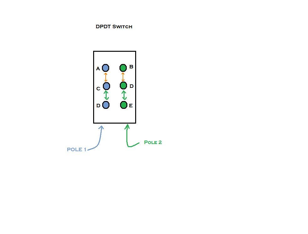 Now, the black wire from the bridge pup goes to what I have shown as "lug C" on my diagram- but it is also connected from there to the phase switch on the other pot, and from there to the series/parallel switch, and from there, through the pots, the selector switch, and on to the output. The black wire doesn't really need to be connected there, it was just a convenient place to take it to. It could just as easily have gone to the phase switch directly. What is important with that switch is what happens with the red/white wire pair. The switch is used to cut the bridge to a single coil, which is done by shorting that red/white pair either to ground (via the black wire to the phase switch which connects to lug "C") or to the "hot" (via the same black wire, when the phase switch is flipped the other way). Shorting the red/white pair to ground selects one coil from the HB; shorting the red/white to the "hot" selects the other coil. The coil cut switch for the neck pup operates the same way, but it doesn't connect to the phase switch, so it looks a bit different. It's also wired "backwards", so that you get the opposite coil from the bridge when both coil cut switches are "on"; opposing coils from the neck and bridge will be hum-cancelling. |
|
vhgtar00
Apprentice Shielder
Posts: 28
Likes: 0
|
Post by vhgtar00 on Nov 2, 2014 12:29:57 GMT -5
In my previous post, I was confused about how the JP Wiring diagram worked. I am no longer. I understood how DPDT switches worked. What I didn't understand was how the tone pot filtered the signal. I now understand that the whole signal doesn't pass through, but rather only some of it. Then, whatever the capacitor filters off goes to ground and the remaining signal 'goes back' to the output. I completed a wiring diagram that I believe works, and I'd like someone to evaluate it for any errors I might have made before I implement it. 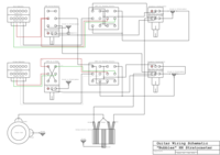 Schematic Controls: Neck Master Volume: Controls Master Output of the entire N pickup Neck Spin-a-Split: Controls the volume of the 'blending coil' Bridge Master Volume: Controls Master Output of the entire Br pickup Bridge Blend Volume: Controls the amount of volume outputted by the 'Blending coil' Neck Spin-a-Split Coil Selector Switch: Switches which coil is considered the 'blending coil' Bridge Spin-a-Split Coil Selector Switch: Switches which coil is considered the 'blending coil' Neck Tone P/P: Switches between N+Br and N*Br Bridge Tone P/P: Switches Br in and out of phase with N --- When writing down the controls, I just thought of an error in the diagram. The way I wired the Spin-a-split selector switch does not create a pair of humbucking coils in each similar position. As an example, if both switches are set to position one, then both of the pickups' 'blending coils' will be set to south as opposed to having one north coil and one south coil. It isn't necessarily a problem. All I have to do is switch the wires from the top row (pos 1) with the wires from the bottom row (pos 2) which is basically a reflection of the neck switch's setup. With that aside, are there any other problems you guys see? Thank You, vhgtar00 |
|
|
|
Post by JohnH on Nov 2, 2014 16:14:42 GMT -5
Hi V
I fear there are several nasty issues lurking there. But I think you can fix them and also simplify the wiring too. The main simplification is a single pole for the blend coil selects instead of 4. Problems I see are around the series/parallel and volume wiring. Also, in series mode, if you fade one coil down on the pickup nearest to hot, which is done on tbe diagram by groundjng it, then it also cuts out the other pickup.
Best to develop this design by thinking of it as two entirely seperate modules. One for neck, one for bridge. They dont meet at all until after their pots and switches, at the three-way and series/parallel switch, then to the output. Each module has a virtual hot and ground. Only one of these 'grounds' is permanently grounded. The other gets switched from ground, to the 'hot' side of the other module.
For say, the bridge pup join red to white permanently. Take that point via the coil blend pot to the pole of a switch that connects it either to black or green. That gives you the coil select and spin-a-split. Take black and green to your phase switch to swap them. Then to tone then volume with output from middle lug (treble bleed recomended too). End of module. I suggest drawing that first.
Neck module is identical, but no phase switch. Possibly swap red with black and green with white so you get a humcancelling pair of singles with default switch positions.
Two seperate drawings there. Then we can combine them to complete the design with the 3-way s/p switch and output.
|
|
vhgtar00
Apprentice Shielder
Posts: 28
Likes: 0
|
Post by vhgtar00 on Nov 4, 2014 17:32:12 GMT -5
JohnH, I'm realizing quite a few problems now that you've pointed it out. I don't quite get the SPDT switch yet because my frame of mind is in this following diagram and trying to send four different wires to three sources (vol, split, ground). cdo.seymourduncan.com/blog/wp-content/uploads/Spin-A-Split.gifi will get back with a V 1.1 Till then, vhgtar00 |
|
vhgtar00
Apprentice Shielder
Posts: 28
Likes: 0
|
Post by vhgtar00 on Nov 8, 2014 11:04:59 GMT -5
JohnH,
You said:
I can't seem to wrap my head around the idea of the Coil Select Switch in the way you implement it. Only the Black and Green wires or the Red and White wires joined can go to the coil blend. The unused Start goes to Volume and the unused Finish goes to ground. Could you explain exactly how I could use that SPDT?
vhgtar00
|
|
vhgtar00
Apprentice Shielder
Posts: 28
Likes: 0
|
Post by vhgtar00 on Nov 9, 2014 0:07:42 GMT -5
|
|
|
|
Post by sumgai on Nov 9, 2014 4:18:55 GMT -5
Errrr..... v-baby, what's with this ".jsch" file extension? Howzabout attaching a regular image file that all browsers* can unnerstand, please? For those of you who aren't clued in, the New and Improved buzzword-of-the-day is Java Secure Channel. Don't bother checking it out, as soon as you get it typed into your favorite search engine, the top-most results will be from The Wayback machine. All that we really need to know is that it's not a file type, it's a Java-based implementation of SSH2. Which I'm pretty sure ProBoards is not ready to handle just yet, but that's a story for another day. * Well, except Pine and Lynx, but I doubt anyone's still using either of them. |
|
vhgtar00
Apprentice Shielder
Posts: 28
Likes: 0
|
Post by vhgtar00 on Nov 9, 2014 16:55:07 GMT -5
Sorry about that. I was using JSchem to create the diagram and forgot to upload the image this time around.  |
|
|
|
Post by sumgai on Nov 9, 2014 18:43:19 GMT -5
v...., I just took the first 10 results from Google, telling me that .jsch is a file extension for use with the Java Secure Channel protocols. If there's some program out there that uses the letter "J" as an indicator that it too is "New and Improved" way of doing the same-old, same-old, then the authors of such a proggie had best be getting on the stick, and alerting Google to that little factoid. As to your latest revision, I'll just give you an overview of what I found: Suffice it to say, you're missing a way for the Neck pup to be heard, if the Neck "choose-a-coil" switch is pointed downwards instead of upwards. And that's just the start of your Neck pup circuit woes. If you go for Series mode, not only will nothing be heard (due to that Neck problem I just mentioned), but you also won't be able to reverse the phase between the two pups - that switch is now out of the circit. Just about as bad, from your standpoint, is the fact that Bridge Vol pot is also null-and-void at this juncture. To cure both of those issues, it'd be best to simply move the OoP switch, the associated 'choose-a-coil' switch, and the Vol pot so that they're in the Bridge's hot line before it goes to the Ser/Par switch. Also, as a matter for consideration, think about how you want the Ser/Par switch to work - only when both pups are selected; or as an "over-ride", meaning that it trumps the pup selector switch (it all goes to Serial no matter which way the pup selector switch is positioned). That might make a difference in how you fix the Neck circuit's problems. HTH sumgai |
|


 )
)

 But if you're gonna use one concentric dual pot for the Vol, why not a second for the Tone controls, too? Then you'd replace the third pot with that spring loaded pushbutton switch I mentioned earlier, for the Kill function. (Or the 3 position (one momentary) toggle switch, depending on your needs/wants.)


 ??). When the pot is up, pole 3 gets connected to throw 5 which is where the red and white wires connect. Again, I can see nothing happening.
