|
|
Post by ashcatlt on Mar 28, 2015 12:37:00 GMT -5
Some of you might be aware that I've been writing some "analog simulation" plugins using the JSFX engine in Reaper. I've got a few "pedals" that I've built. I've also got a super simple, but surprisingly decent sounding "amp sim" thingy that works really well to give some character to things where I don't really need the character of any specific amp, but I'm still using PodFarm for most of my actual guitar tracks. Even just the amp/cabinet module from PodFarm uses an inordinate amount of CPU, though. I've been using GuitarRig on my live machine because it's a little bit lighter, but it's still using like 10 times the CPU of my "sin amp", and I find myself wondering how close I can get with a bit more efficiency by writing my own. I'm betting I can get "plenty good enough" for my purposes with a lot less load on the poor processor. In order to get where I want to go, I need to get my head around some things in a "real" amp, and unfortunately I'm a bit blurry when it comes to the details of tube design. That's why I put this here in the Amps section instead of the Computer-Aided section. I don't (right now) need help with the code, but with actually understanding how the meatspace monsters work. Of course I'm shooting for an AC30TB first, though I hope to just understand basic principles that I can extrapolate to other makes and models later. Here's a schematic, for reference:  So, first thing I need to know is how I can tell where each stage clips. How do I look at this schematic and figure out the maximum (and minumum) voltage limits on the output (or input?) of the preamp tube, for example? Bonus points for how to find the nominal gain of a given tube stage. Then I also need to figure out how to make something similar to that tone stack. I understand that the controls are somewhat interactive, and that's fine. Is it possible, though, to model this as discrete LPF, HPF, and/or BPF mixed together? I can easily share and or copy and scale various parameters between three filters in practice, but I'm having trouble analyzing this particular stack, and haven't been able to find a good reference online to explain it. It seems to be closest to the standard Fender stack, which is pretty well documented (which is not to say I completely understand it either), but it's not quite the same. It almost looks like the James stack, for which I can find some pretty extensive analysis, but that ain't quite right either. Might be I'm missing something fairly obvious. I don't even know how to describe what I think I don't understand. Kinda just need a little shove to get over that hump. Any and all comments, questions, guidance, explanation, links, or whatever would be greatly appreciated. |
|
|
|
Post by sumgai on Mar 28, 2015 14:21:47 GMT -5
ash, OK, I'm on it, to a degree.... This is gonna take more than the few moments of time stolen whilst eating breakfast, so I think it's gonna be tonight before I can settle in with some time, and an allegedly alert mind... we'll see what I can come up with for you. In the meantime, anyone else wants to chip in, don't let me stop you!  sumgai |
|
|
|
Post by JohnH on Mar 28, 2015 14:30:43 GMT -5
We'd better let Sumgai take the lead in the tube-figuring. Interesting question though. My approach to that would be to set out to model each stage in a Spice program and explore it, but there is no doubt a dusty looking text book written in the 1940's that has it all set out. For the tone stack, if you can see frequency response plots, would that be enough to let you wrangle your plug-ins to match it? If so, the Duncan's Tone Stack calculator has that exact circuit built it, and you can slide sliders and change values: Duncan's Tone-stack Calculator I would doubt that you could exactly match it by a series of separate filters one after the other in real RC components, but in the virtual world maybe you have more freedom to make one part dependent on another using parameters that you create. It is probably obvious that I have no idea what I'm talking about! |
|
|
|
Post by ashcatlt on Mar 28, 2015 15:43:07 GMT -5
Thanks both! This is not super urgent. For the tone stack, if you can see frequency response plots, would that be enough to let you wrangle your plug-ins to match it? If so, the Duncan's Tone Stack calculator has that exact circuit built it, and you can slide sliders and change values: Apparently not. I was playing with that the other day, and it kinda just confused me more... I wasn't actually playing with filters or code at the same time, or really had a lot of time to dig into it though. But yeah, I can make all kinds of "ganged pots" and whatnot in code, that ain't really a problem. |
|
|
|
Post by sumgai on Mar 29, 2015 2:18:05 GMT -5
.... So, first thing I need to know is how I can tell where each stage clips. Far too many variables to determine this, sorry to say. The biggest problem here is bias. In the circuit under review, we're looking at cathode bias (or self-biasing) on the pre-amp tubes, and that changes the gain factor for any given input voltage, and thus the clipping point. More on this in a moment. Short answer: you don't. You need to find and read the tube's specification chart. There are lots of figures given on such a chart, but you'll find the exact numbers you're looking for, no problem. More to the point, (I think) you want to know what a given circuit can withstand, not just the tube itself. That's not any easier, but working with the chart and with some info from the link below, you can probably get close enough for your purposes. Here's that link I mentioned. Follow all of the page, as it builds from point to point, but in essence, Point #4 is what you want. sound.westhost.com/valves/bias-gain.htmlKeep in mind that his treatise is fairly general, and I did catch at least one mistake in his component descriptions, but by and large, it beats my repeating it.  I don't see why not. For the most part, it's the same thing as an older Fender tone-stack, except that the Middle tone range resistor is tied to the Bass control's wiper, instead of the "grounded" terminal. That makes for a lot of interaction, as in the 10KΩ resistor is essentially shorting the Bass control. (Not much good, in my personal opinion. OTOH, Vox has bit more spending money in their pocket than I do, so I guess we can see who's the winner here.) But what does that mean for your simulation? Why, nothing at all. You're after emulating the tonal results - how you get there has no bearing on how Vox did it, amiright?  Your bit about LPF, HPF and BPF is exactly where you need to go, and overlapping their frequency ranges is what's needed. Now, what are those ranges? I think some LTSpicing is gonna be needed here. I think you did fine.  Of course, I made some assumptions in my reply, and if they're off-base, then you'll have to straighten me out. Hopefully, the shove didn't send you over the edge! HTH sumgai |
|
|
|
Post by ashcatlt on Mar 29, 2015 9:44:13 GMT -5
sg - I've seen that link, and went back through it, but it's not really getting me where I need to be. Maybe my question wasn't specific enough. I can use that thing or a couple other sources to figure the gain (though it's ugly), but then what? The only thing that page really says about limits is the thing about how the input signal should never be more positive than the cathode bias or the positive peaks will get clipped. So fine, what about the bottom of the wave? I'm absolutely sure that it can't just swing forever in the negative direction! Where does it stop? This is very frustrating. If I'm trying to figure clipping points for an opamp I pretty much just look at the power supply. Output will never be more positive than the positive rail or more negative than the negative and I'm (about) done. It frankly doesn't matter how much gain I apply in the process. The output had clearly defined limits. The tube stage also has clearly defined limits, but I can't seem to find a straight answer on what they are. How close to ground will it get? How close to the top rail? Edit - Maybe I made my question seem too complicated when I used the word "emulate". I'm not talking about much real modeling here. I'm just going to run the signal through a sine clipper. Basically just take the sine of the input. Of course, we scale and limit that input so that it swings between -pi/2 and pi/2 so that it doesn't fold over. I need to know how to do that scaling so that it hits pi/2 around the same point where the stage would clip in the actual circuit. Edit again - This seems to be a pretty deep analysis of the same preamp. They come to a gain of about 74 in the first stage, and a Grid bias of -1.8V, which I think means that the positive limit on the input is 1.8V. 1.8 * 74 ~ 133, which is a little less than half of the VPP at the top of the tube. Can I assume that the output swings around half of VPP and won't get get greater than VPP or less than 0? Or... |
|
|
|
Post by JohnH on Mar 29, 2015 16:15:25 GMT -5
Taking that first stage in the page that you linked, the grid is biased to ground, 1.8v below the cathode in steady state conditions. The cathode is bypassed by a large cap that will mean that cathode voltage hardly changes with audio signals. So even if the tube switches on with a very low resistance due to an up-swing on the input, the output plate voltage cant get below 1.8V.
But are you just wanting to model a pure sine wave with a hard clip?, or do you want to capture the tonak non-linearities of soft clipping of a tube circuit?
|
|
|
|
Post by ashcatlt on Mar 29, 2015 16:48:49 GMT -5
Ultimately and eventually I would be interested in finding a relatively accurate model of that non-linearity, but for now the sine clipper is that model. It actually tracks pretty closely to the log curve you get from a diode, and in sounds pretty good to me. If you've got an idea for a function that will get me closer to "real tube action" without requiring any more of the CPU, I'm all ears. tanh works really well for diodes, but requires some pretty hefty humping comparatively. I tried a 2/3 power thing, and it was interesting, but I don't like that it never really limits...
So, we're saying that 1.8V is the bottom of the output swing. Can't go below that no matter what we ask of it. Of course, this is an inverting stage, so it's the positive swings that will push it to this limit, but that's pretty arbitrary. Where's the top of the output? Will it go all the way to VPP? For that matter, where's the middle? Where am I? WTF is going on?
|
|
|
|
Post by JohnH on Mar 29, 2015 21:53:00 GMT -5
Im in deep over my head.
But Id expect that the tube can be made to switch off, so the upper limit is the top supply rail 275V, that is, ignoring the load on this stage, which is the volume pot. So with no pot there, swing is from 1.8V to 275V, or a bit less according to some tube parameters that I do not understand. That is reduced by the load of 1M due to the pot, so the whole stage has a net swing reduced by a factor of 1M/(1M+220k)
But what is the steady state plate voltage? the link says it is 190V, which is 85V below the supply. But if there is 0.6mA running in steady state, there would be 0.6 x 220 = 132V across the 220k plate resistor, rather than 85V. At which point I sink beneath the waves of confusion.
|
|
|
|
Post by ashcatlt on Mar 30, 2015 11:19:14 GMT -5
I'm not completely sure that the tube actually goes all the way to open circuit, but honestly at these levels a V or two either way is well within the tolerance of the compinents, and likely not an audible difference.
What would make a difference is that 65V difference at the center. 132V is pretty well centered, but 190V is starting to get pretty assymetrical, with the bottom of the swing like double the headroom of the top.
|
|
|
|
Post by sumgai on Mar 30, 2015 12:32:31 GMT -5
Hmmm, time to stick my barnacle-covered oar in the water again.... Recall that tubes (valves, in non-standard English parlance) deal with current, not voltage. In summary, tubes don't care about voltages. In fact, the only reason we need a high voltage (1) (compared to solid-state) is because we need to move electrons off of one element and through a vacuum to another element - that takes power, not just voltage, as in current X voltage = power. (But in a pre-amp stage, that total power is miniscule, granted.) All this talk about voltages in and out is misleading - we need to know the current flow through the grid circuit and the plate circuit (2). Only then can we calculate the voltages expected to be seen at the incoming "current limiter" resistor (3) and the plate's load resistor. Even then, those are approximations, but I'd think they'd be close enough for simulation purposes. Oh, and don't let any talk about bias voltages sway you away from these statements - bias voltage is intended to shift the absolute voltage level in reference to ground, so that a tube can operate in linear fashion, that's all. It's the absolute values with which are concerned here, not the observed values (such as readings taken with a meter, in a real-life working circuit). In fact, several places around the web will attempt to have you obsess over the bias current - that's a red herring... but it's also a story for another day. Now, how does all of that relate to formulating a simulation in software? I dunno, I'm not privy to whatever parameters can be controlled in said software. I do know this though - if one can't designate a given current, in milliAmps or otherwise, then one is somewhat crippled before even starting to write any code. In my humble opinion, of course. The best one can hope for is to designate a basic resistance value, calculate the approximate voltage expected to appear across that resistance, and plug that number into the code - hopefully that'll be close enough, but I won't swear to it. ash, my apologies, I know all of this blather didn't help much, but it does go a long ways toward explaining why there's such a dearth of good (read: correct) info on the web, vis-a-vis how tubes operate, and how to emulate them in software. Us tube-cognizant old-farts are a dying breed, and that's the sad state of affairs. sumgai 1. In point of fact, many circuits exist that use a "standard" 12AX7, and drive it with only 12 vDC to the plate, or even less! The results are interesting, to say the least. Google is probably your best friend here, if'n yer interested. 2. Talk to b4nj0, he's an Amateur Radio Operator (as was I, in an earlier life). Ask him about dipping the grid and peaking the plate. I think we may have one or two other hams around here as well..... 3. According to my link several postings above (sound.westhost.com), the incoming grid resistor is a "stopper", meant to block, or at least reduce, AM radio interference. It's comically obvious to any first year EE student that the author in question slept through that particular class lecture... That resistor is properly called a "current limiter". Its job has nothing to do with radio interference, instead it's meant to take advantage of Kirchhoff's Law, the one that states that the current passing through a component is the same as the current found through all the other components in a series circuit. Don't believe me? Then tell me, how would you calculate the voltage drop across a known resistor, if the current was some fractional value? (And yes, I'm speaking to an instantaneous value here, for example purposes only. In a real-world working circuit, that value is constantly changing, but only in step with the signal level presented to a given component.) By limiting the current from the previous stage, we (try to) keep the input of the following stage from being swamped. |
|
|
|
Post by JohnH on Mar 30, 2015 15:26:24 GMT -5
Heres another link that I found helpful, from ax84.com: preamp theoryThis one seems more helpful and consistent. A similar circuit is analysed and explained. Values are different. Its based on a 274v supply with 100k plate and 1.5k cathode resistor. It shows a cathode voltage of 1.39v and plate biased at 181v |
|
|
|
Post by ashcatlt on Mar 30, 2015 17:59:51 GMT -5
sg - I definitely do appreciate your input. I understand what you're saying about how it's the current through the tube that makes it all happen, and it reminded me that it's really the same thing going on here as in a transistor amp - voltage on one terminal controls current between the other two, causing a voltage drop across some resistor... I certainly could do that in code, but from my perspective all that really matters is the voltage present at the input of the next stage. Ultimately, in the linear region, all of that transconuctance action just amounts to a fixed amount of gain, which is simple multiplication. The curviness at the extremes can be approximated a number of ways, and while I'm now talking about the sine clipper here, it's almost arbitrary.
But I am now seeing that the lowest output possible is when the most current is flowing - when the tube is as close a short circuit as it will get, and likewise the highest output will be when the tube is as close to an open circuit as possible. I guess I still wonder how close to short/open it actually gets, but like I said up above if that leaves a V or two short of the actual open/shorted voltages, it shouldn't make much difference. I'm thinking that just using that VPP voltage and ground as the limits in either direction is a decent eyeball, at least for this particular stage.
Then there's the question of symmetry. I'll have to dig into that most recent link John posted a bit deeper when I can find some time. Is it possible that assymertical non-linearity in the transconuctance kind of undoes the assymetry of the quiescent voltage? Like, the it has further to go to hit the bottom rail but it takes less change at the grid to get there? Or...I that 190V figure that made JohnH's head explode just a red herring?
|
|
|
|
Post by sumgai on Mar 31, 2015 0:45:36 GMT -5
ash, I guess I may have "over cooked" the turkey, eh? When it comes right down to it, Engineers versus Technicians (current versus voltage) doesn't really matter, so long as the job is accomplished to everyone's satisfaction. Engineers just have a bigger ego in defending their position, probably because they spent a lot more money on their education. I looked at John's link, and for a quick read, I saw nothing with which I could argue. I've long known about ax84.com, several of the mainstay participants are EEs, so the theory is pretty solid. The math appeared to be pretty minimal, so that's a plus. While that page (actually, a PDF file) may not answer all your questions exactly, it should get you good ways down the road. Or in other words, I couldn't've written a better treatise myself, and I don't want to reinvent the wheel here, either. (Hint: I think you're gonna find that the gain curve doesn't go all the way between ground and B+, nor does it stop just a few volts short of those limits - in fact it's quite a bit less than that. The relevant pages of that PDF file that deal with this, and how to calculate gain, are 11 thru 17. Start there, and see what jumps out at you.) As to simulations and emulations, I think at this point you're gonna be best advised to simply suck it up, and jump right in! Start with whatever feels like a good set of numbers, and see what happens. The game of the day is Tweak, Tweak, and Tweak some more. I know, it seems like hit-and-miss, and it is.... but when the teeth-gnashing and hair-pulling are all over and done with, you're gonna have one hell of a hot-rod circuit (in some form of simulation) than you just might be able to put on the market - who knows, worse things have happened. sumgai |
|
|
|
Post by ashcatlt on Mar 31, 2015 11:50:15 GMT -5
Well, a big veil was just lifted for me. I suddenly understand how to use those graphs to find the answers I've been looking for. If I'm right, then it's almost too easy.
Draw the load line for the plate resistor. Where it hits the x axis of the graph is the plate voltage at cutoff, and where it hits the 0 line is grid conduction. Those are my limits. Find the point on that line for the quiescent voltage. The voltage difference between that point and the actual midpoint of the load line segment of interest is basically a DC offset which causes asymmetry.
I think I can work with this for the moment. I had 5 sine clippers in a row running last night and it used 0.6% CPU. There's no filters in there yet, but filters are really just a couple multiplies and a couple of adds. We'll see where we end up. The PodFarm Class A30 was showing like 6.5% CPU, though I found out that if I turn the actual amp off (switch to power amp - straight wire with gain) and just leave the cabinet, it drops to 2.3%. I'd imagine they're probably oversampling in there somewhere and whatever, but then the VST format is supposed to be a bit more efficient than JS. There's a guy over on the forum who has a big running start in the direction of an automatic JS to VST conversion utility that I'm pretty excited about.
I'm going to play with things a little now that I think I've got a better handle on the voltages at play, and then maybe dive into the various filters. I think I've got an idea of how to make that tone control work...
|
|
|
|
Post by reTrEaD on Mar 31, 2015 23:36:08 GMT -5
But what is the steady state plate voltage? the link says it is 190V, which is 85V below the supply. But if there is 0.6mA running in steady state, there would be 0.6 x 220 = 132V across the 220k plate resistor, rather than 85V. At which point I sink beneath the waves of confusion. John, it would appear there is a serious error in that link: www.ampbooks.com/mobile/classic-circuits/vox-ac30-preamp/The load line should be drawn between: 1 - the point where the plate resistor (220k) sees the entire supply voltage (275v) and the voltage on the plate (theoretically)is zero. *and* 2 - the point were there is zero current in the tube (and plate resistor) and the plate is at the same potential as the supply. The left end ( 275v / 220k = 1.25 mA ) is correct. The right end ( 0mA, 275v ) is not. It's at 375v. With a fundamental flaw like that, things won't come to adding up. |
|
|
|
Post by ashcatlt on Apr 1, 2015 10:28:58 GMT -5
Shoot! I think I missed that, too. Better take another look here when I get a chance.
I figured out that everything I need is on that load line plot. You can find the gain just by following the load line from one of the gridV lines to the next to find the plate voltage change for a given amount of grid change. Find the quiescent plate voltage by drawing a line for the grid resistor between any of the gridV lines, and where it hits the load line is where it will sit. It's almost too easy!
I also found that the scheme for the 90s AC30TB is a lot easier to follow, partly because it doesn't have the whole reverb thing in the way, and partly because it's just drawn more clearly. That one has the VPPs specifically called out, but they're different from what ampbooks is saying.
I think I've got all the tubes ready to rock. I'm only actually going to use one push-pull pair, though. Theoretically each of the tubes on one side will do about the same thing, so that adding their outputs won't affect the actual curves, basically just linear gain, so we'll save a couple ticks there.
Now the filters. I'm pretty sure I know how to handle the tone stack at this point, but I'm gonna have to look at it a bit.
Then I gotta figure out what to do about the speaker/cabinet emulation...
|
|
|
|
Post by ashcatlt on Apr 4, 2015 13:00:13 GMT -5
I've worked up a couple of functions for shelving filters like this: 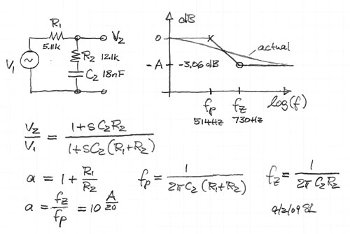 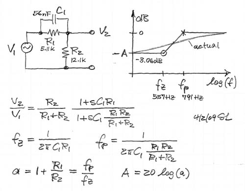 You tell them R1, R2, C, source and load resistance and it just filters and shelfs. I'm using these for the Brilliant V, the tone stack, and the cut. I'm not going to get too far into the details right now, but I think I've got everything but the Cut knob. I understand that it's just really a low-pass that affects both phases going into the power tubes, but there's just a mess of lines and squiggles around that area, and I don't know for sure how to figure any of the parameters I need to send the function. I'm sure a bit of Thevenin and Nortoning will get me there, but I haven't had the time or attention span to untangle that web just yet. Edit - Oh! And we played an entire show last night with nothing but sin_amps and it was pretty darn rockin'. The sin_amp is a really simple plug - gain > sine clipper > parallel all-pass filter > high and low pass "bookends" which was originally intended for background synths and other things that I didn't think deserved the CPU hit of PodFarm or even GuitarRig. But if I put ReaEQ on one side to act like the tone stack and another on the other side to act as a cab/mic simulator, I get really close to what I'm shooting for. Definitely good enough for me to get my thing across in a live setting. It just makes me even more excited for what this AC sim is going to do. We ran the whole robot band behind us and the CPU was maybe at a fast walk pace, no sweat at all. |
|
|
|
Post by JohnH on Apr 4, 2015 23:53:23 GMT -5
Looks like you are making good progress.
I like a bit of math (but not too much). So I thought I'd plot your shelf filter the way that I do them on spreadsheets:
Its based on complex numbers, ie numbers in a 2d grid across the page and up and down the page, instead of in a line. I like to think of them in a graphical way, as below, plotting impedances and resistances.Tthe resistances are plotted across the page (here with the 5.11k and the 12.1k), and capacitive impedances are plotted downwards (ie zC = 1/(2PiFC)
The ratio of the output voltage V2 to the input voltage V1 is the ratio of lengths A and B as plotted. ie, its a voltage divider in 2d. You work out lengths A and B by Pythagoras, and take the ratio, same as you would for a simple resistive voltage divider. The phase lag can also be deduced from the angle between A and B.
illustrated here at 1000hz, at which the capacitor has an impedance of 8840, with a plot in db
|
|
|
|
Post by ashcatlt on Apr 5, 2015 13:29:09 GMT -5
Just realized I had posted double of the "down shelf" instead of the "up shelf". Fixed now. I gave myself a crash course on that whole imaginary number, vector math thing, and I'm glad I did, but for what I'm doing it's not actually necessary to go that far. After all the Pythagorizing, you come up with the number where the filter itself is down 3db - what's called fp on the pics I posted (not mine BTW). And that's all I need. It works out exactly right if you take two copies of the signal, highpass one and lowpass the other at exactly the same fp, and mix them together based on DC voltage division of the resistors around it. For one of them, figure the ratio with the capacitor open, and for the other you figure it with the cap shorted. Apply those factors and then add them together. The volume control works exactly this way, too. The trick is in figuring out which which is which with all the resistors going all over the place. Is that R2, or part of the load? Is it R1 or part of the source? Or is it the load? Then we get a pot involved so that the top half is part of the load, but it's in series with another pot and the bottom half is part of R2, but in parallel with this other thing over here... Even the volume control is really just a shelving HPF with a presumed very large load, the tube for the source, and R1 and R2 split across the pot. Another part of the trick is keeping things from exploding by trying to divide by 0. At the moment it's just random chunks of code - some completely untested and in various states of disrepair - that is not functional as a cohesive unit, but once the functions are written and all of the variables set appropriately, it becomes a simple matter of calling the right functions in the right order every time a sample comes in. To start with the thing will be running DC coupled with an ideal bipolar voltage supply. I haven't decided how much impact any of the highpass action of the tube bypass caps actual has at audio frequencies, so I'm ignoring them completely, but the asymmetry of the stages alone will cause a DC offset between stages which I need to strip out at the points in the circuit where there are coupling caps. I have a pretty good idea of how accomplish a "softer" power supply, but things I've read say that the mostly Class A operation means that current demand at the power tubes never really changes enough to cause noticeable sag. I have stupid ideas of actually rectifying a sinusoidal power supply, feeding a filter, and letting it discharge via the demands of the rest of the plugin, but we ain't quite there yet. I know it's not worth it for my live rig, but I will eventually probably do it for science. |
|
|
|
Post by JohnH on Apr 6, 2015 16:20:35 GMT -5
Will look forward to hearing results in due course!
What interested me about the shelf filter was to see how the two theoretical frequencies compare to a plot of actual response. Usually with a simple HPF or LPF, those frequencies mark the -3db points, where resistance = capacitor impedance and signal level is down by a factor of sqrt2. But here, the overall step is only about 3db total so the curve cant develop its theoretical maximum gradient of 6db per octave before it has to flatten out again for the lower shelf. If you were choosing two frequencies to best capture the response in a tri-linear flat-sloped-flat arrangenent; they would pribably be wider apart, maybe sloping between about 200 and 1100hz. I dont know if that is important audibly though.
|
|
|
|
Post by ashcatlt on Apr 9, 2015 19:19:50 GMT -5
Any ideas at all on that Cut control?
|
|


 Your bit about LPF, HPF and BPF is exactly where you need to go, and overlapping their frequency ranges is what's needed. Now, what are those ranges? I think some LTSpicing is gonna be needed here.
  Of course, I made some assumptions in my reply, and if they're off-base, then you'll have to straighten me out.
