shadowfall
Rookie Solder Flinger

Posts: 22 
Likes: 0
|
Post by shadowfall on Feb 27, 2016 13:50:30 GMT -5
Hello!  I am looking for a wiring diagram so my pickups do the following: 6 way humbucker switch : North coil/South coil/Parallel OOP/Series OOP/Parallel/Series Then 6 way for the HH combinations: Neck/N+B parallel OOP/N+B Series OOP/N+B parallel/N+B Series/Bridge Every pickup has 1 tone and 1 volume Is this possible? |
|
|
|
Post by sumgai on Feb 27, 2016 23:43:20 GMT -5
shaddy,
Yes, you can do this, but I gotta tell ya, this will almost certainly be the first guitar I've ever seen where the switches alone cost more than the whole rest of the guitar is worth!!
When visiting this website, you'd better trot out two checkbooks, because whatever you've got in just one, it won't be enough:
The FREEWAY switch, from Stewart-Macdonald
HTH
sumgai
|
|
shadowfall
Rookie Solder Flinger
Posts: 22
Likes: 0
|
Post by shadowfall on Feb 28, 2016 7:25:17 GMT -5
Hah thanks.Pretty costy for sure.But i think im gonna do it.Are there any of the wirings i want (the HB alone or the one for the HB selection) on the site?Because i didnt find anything.Or maybe i dont know how to search  |
|
|
|
Post by ashcatlt on Feb 28, 2016 11:18:39 GMT -5
I'm sure you could find 4P6T rotaries much cheaper, but...
Have you actually heard these combinations that you're suggesting? Generally, switching between coils in a HB - especially at the neck position - makes very little difference to the overall sound. Because of that, putting both coils of an HB out of phase with one another leaves almost nothing but noise. It does make some sense to select the appropriate coil for humcancelling in combination with the other split humbucker, and that will be different when they are inter-pickup out of phase. I suppose the intra-OoP positions will have an effect on the tone when combined with the other pickup because of changes in overall inductance and resistance, but IDK if that's really worth it.
|
|
shadowfall
Rookie Solder Flinger
Posts: 22
Likes: 0
|
Post by shadowfall on Feb 28, 2016 13:05:07 GMT -5
Ye im aware of the hum noise,the sounds and all these stuff.I havent heard all these combinations.I have half of these in my guitar.I just dont have the out of phase thing and i also cant use 1 split coil plus a humbucker.But it looks to me that its better these way cause i dont need an ultra sophisticated thing with switches and crazy stuff in it.Ill just have the sounds that i want in 3 switches.I saw a similar thing from a guitar maker that had all the combinations lets say.Plus sometimes noises and weird sounds are fun.
|
|
|
|
Post by newey on Feb 28, 2016 22:49:19 GMT -5
Shadowfall-
Hello and welcome!
As to the Stew-Mac "freeway" switch, be aware that there are two versions of this switch. The original version was set up for certain designated wirings, and was not a true 4P6T (i.e., it didn't have 24 wire-able lugs). The newer one is a true 4P6T toggle; I think they call it the "ultra" version or some such. Not sure if the original version can do what you want it to do- it probably can't.
Ashcatlt's suggestion to use rotaries instead is, I think, a good one. A toggle switch is, in principle, easier to switch "on the fly", in mid-song for example, since on a rotary one must go through other positions. But with a 6-way toggle, the odds diminish that you can quickly get to the position you want- it'd be easy to "miss a shift" so to speak. So, on the "ease of use" front, I'd call it a wash. On "ease of wiring", I'd give the edge to the rotaries.
|
|
shadowfall
Rookie Solder Flinger
Posts: 22
Likes: 0
|
Post by shadowfall on Feb 29, 2016 7:09:31 GMT -5
I dont have a problem with rotaries,these are cool too!i just want a diagram that does that thing (or things haha)
And btw thats like the best forum ever.First thread and i got all the admins and mods trying to help.
|
|
|
|
Post by newey on Feb 29, 2016 22:45:31 GMT -5
Well, it is a fairly Nutzy™ scheme. This sort of thing tends to bring us out of the woodwork.
As for a wiring diagram, let's decide for sure on what switches you'll use before we start putting pen to paper(or, more properly, before putting pixels on screen . . )
Whichever switches you do choose, however, this can drawn to be a modular design, if you are willing to accept that all 3 switches have their selections in the same order (which is not the way you list it). For example, you show each HB's switch having the first 2 positions being "N Coil, S Coil", whereas the "master" HH switch has neck and bridge pickups at the opposite ends of the switch. If you can live with having each HB switch wired such that the N coil and S coil settings were at the ends, with the series/parallel/OOP settings in the same order as on the "master" switch, then we'd only need to draw a single diagram, all 3 switches would be wired identically.
I think doing so would not only ease the wiring, but would in practice be easier to figure out while playing, as all 3 switches will then operate in an analogous fashion.
|
|
shadowfall
Rookie Solder Flinger
Posts: 22
Likes: 0
|
Post by shadowfall on Mar 1, 2016 5:40:43 GMT -5
Thats exactly what i wanted.Something that is fairly "simple".And its a nice idea about the single HB too (being like the switch between HBs)
|
|
|
|
Post by JFrankParnell on Mar 2, 2016 14:35:24 GMT -5
|
|
|
|
Post by reTrEaD on Mar 2, 2016 17:32:52 GMT -5
Good idea.
The Free Way switch doesn't seem to be a true 4P6T switch. At least not according to the connectivity diagrams. It would be wise to put an ohmmeter to the Free Way and verify exactly how it works before designing around it.
Near as I can tell it only has two commons. Each half of the switch acts like a 2P6T with the poles tied together. I believe all the functions necessary can be accomplished, but it will require a more creative approach. With a true 4P6T switch one need only connect the 4 poles to the 4 leads of the 2 coils and work from there.
With the Free Way, it looks as if the puzzle can be solved with the following starting point.
1 - One end of one coil will be connected to "ground"
2 - Both ends of the other coil will be free-floating.
3 - One common is connected to out.
Since two throws are in play in each position, this will allow for parallel connection.
4 - The other common will not be used.
Instead take advantage of the two throws that will be connected together at each position.
This will allow for a series link or grounding one end of the free-floating coil.
I tend to agree with JFrankParnell's thought of using a triple-shot for the local HB connections. But it doesn't allow for local OOP between the two coils of a HB. John reports some usefulness in having OOP coils in a HB when another pickup is also used.
|
|
shadowfall
Rookie Solder Flinger
Posts: 22
Likes: 0
|
Post by shadowfall on Mar 2, 2016 19:10:57 GMT -5
I already have triple shot.We wanna go next level here |
|
|
|
Post by ashcatlt on Mar 2, 2016 21:23:51 GMT -5
Alright, this is a schematic showing a module that you can use for each switch, and for each V/T combination. It's not my best work because I'm at the day job using MSPaint, but I think it gets the point across. Pretty sure I got it right, but maybe somebody could verify. It's based on this thing but uses two more poles to flip phase on the bottom coil/pickup in the appropriate positions. Left to right on the diagram it gives: Top/POOP/SOOP/Parallel/Series/Bottom You'll jam the V/T module between each intra-pickup switch and it's place on the inter-pickup switch. I'm not super happy with the way the V pots work. With the inter- switch in either Parallel mode, turning either V pot all the way down will kill the output of the entire guitar. In either system Series mode, the top pickup's V pot acts as a Master, and the bottom one will be a little weird. Maybe JohnH or somebody can come up with a better plan, but I don't know of a good way to make them work well in all switch positions. The simple answer is don't ever turn either one all the way down unless you really want total silence. If you want one pickup all the way off, flip the switch.  The T pots will interact in different ways depending on the inter-pickup switch position as well. In Parallel modes they both act as Masters (unless the V pots are turned down), and in Series mode, they do the whole Broadbucker thing.  Note, where lines cross without a loopy jumpy thing, they should be connected. |
|
shadowfall
Rookie Solder Flinger
Posts: 22
Likes: 0
|
Post by shadowfall on Mar 4, 2016 22:11:53 GMT -5
Thank very much for all the work I'll wait to see if someone will come up with another solution |
|
|
|
Post by JohnH on Mar 5, 2016 15:36:47 GMT -5
Thank very much for all the work I'll wait to see if someone will come up with another solution Ash's design seems fine to me for what you suggest. The issue of one volume turning down both in parallel mode is not a real problem, and the solutions cause worse issues. But if you want to see more, here is one I did in 2006. For discussion, there are quite a few things id change on it now: LP MaximiserThe idea was to have the rotaries to select combinations from each pickup. I use a 5 way rotary, but a 6 way is fine. But it used a standard toggle to select between pickups, with a series/parallel switch, instead of another rotary. This provides the main toggle as a quick-change switch, easier to flick than twisting a rotary. There is no explicit out of phase between pickups, but each pickup has a single coil that is reversed when in combo with the other pickup, so it has more phased sounds than are needed. This allows hum and phase to be better organised and cuts out a lot of combos that hum, where there are other similar ones that don't hum. Things I'd change: Not bother with the buffer, nor the 56k resistors (which address the volume issue above, at the expense of, something). The treble bleed values can be improved (1nF/150k), and the series parallel switch is shown as 3 pole, whereas we know how to do this with just two poles now. |
|
shadowfall
Rookie Solder Flinger
Posts: 22
Likes: 0
|
Post by shadowfall on Mar 13, 2016 6:55:15 GMT -5
Is any other switch configuration (not 3way i mean) which can get me out of trouble?Btw which program did you use for the maximizer shematics?
|
|
|
|
Post by JohnH on Mar 13, 2016 14:22:51 GMT -5
Is any other switch configuration (not 3way i mean) which can get me out of trouble?Btw which program did you use for the maximizer shematics? Could you describe more about what you are seeking from such a different switch arangement, ie how it want it to be different from the other designs on this thread? I do all my diagrams in MS Word, then take a screen shot and post a gif file. |
|
shadowfall
Rookie Solder Flinger
Posts: 22
Likes: 0
|
Post by shadowfall on Mar 15, 2016 1:41:45 GMT -5
I dont have anything specific in my mind.I am just asking if there is another type of circuit that does the same thing but it doesnt work that way. Also what would happen if i had only one master volume and tone ? I was searching for similar projects and i found this.Do you think this guy's guitar has the same V/T "problems" ? 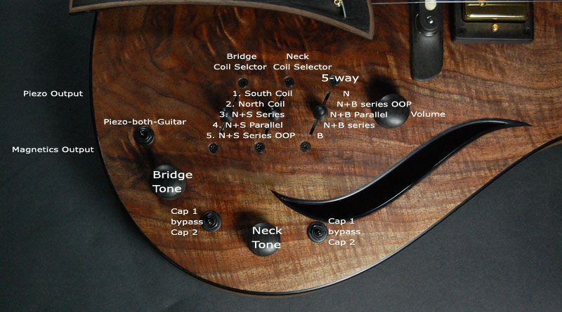 |
|


