|
|
Post by perfboardpatcher on Mar 12, 2016 3:47:26 GMT -5
I thought I'd share this info with you guys. I purchased a bunch of these ones: www.produktinfo.conrad.com/datenblaetter/725000-749999/739679-da-01-en-UEBERTRAGER_1_55V_6000MH.pdfThe label on the transformer says: SK-TECH Electronics Model EF16 - 6.0H The spec sheet mentions an inductance of at least 6.0 Henry but in my case it appears to be a lot more than that! I measured the inductance by using the transformer coil as part of a series notch filter (R=5k6, C=4n6) and I got the following results: 13.0H, 14.8H, 15.3H, 15.8H, 16.4H and 17.5H. The DC resistance for all of the coils was close to 460 ohms. More tests will follow. Paul |
|
|
|
Post by perfboardpatcher on Mar 13, 2016 5:16:39 GMT -5
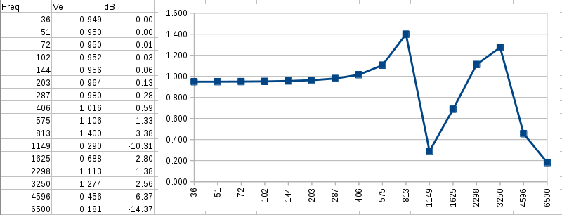
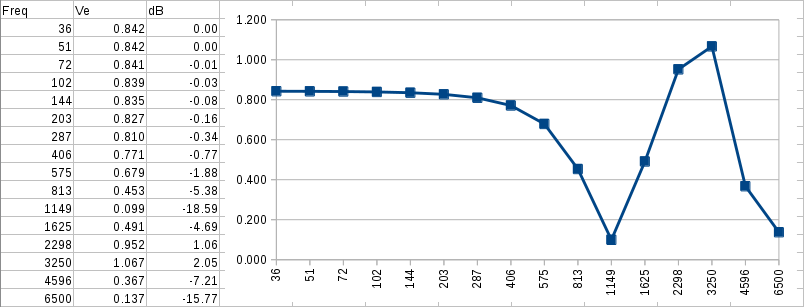
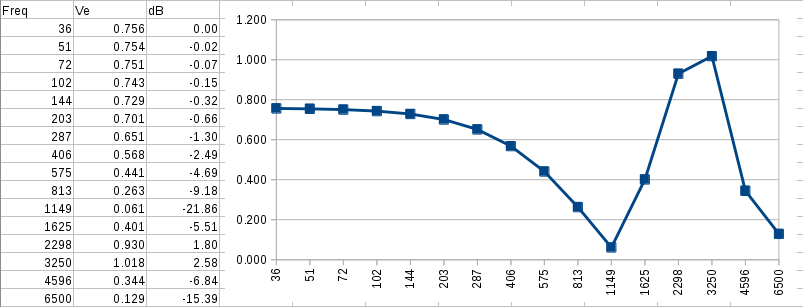
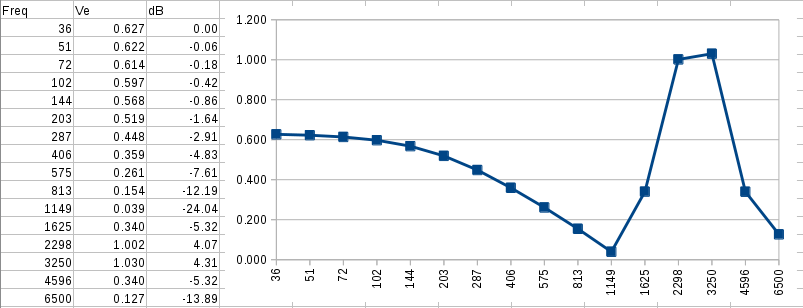
I did some measurements with one of the transformers (L=14.8H) with 3 different capacitors (32n, 4.6n, 1.2n). I also used a scope, signal generator, multimeter and a resistor (5.6k). The procedure is simple. - Use scope to find notch frequency. - Use multimeter to measure the notch frequency - Use scope to determine the attenuation at the notch frequency. The results are presented in 3 spreadsheets. In stead of the ohmic source of 5.6k I've used the impedance of my own guitar pickup (L1-s). The 'onds' represent the loading by cable and potmeter (at 100%) and amp/fx input. V uit (= out) and dB are the results of the notch filter engaged. (Meaning, if not engaged then V uit=1 and dB=0 for all frequencies.) R_Lp is the resistance (at resonance frequency) in parallel with the transformer coil to let the results match reality.
Resonance freq. 230 Herz, L=14.8H, C = 32nF
Resonance freq. 610 Herz, L=14.8H, C = 4.6nF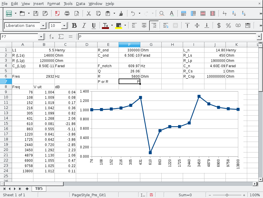
Resonance freq. 1200 Herz, L=14.8H, C = 1.2nF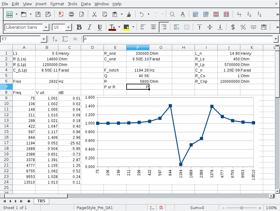 |
|
|
|
Post by perfboardpatcher on Mar 26, 2016 3:22:26 GMT -5
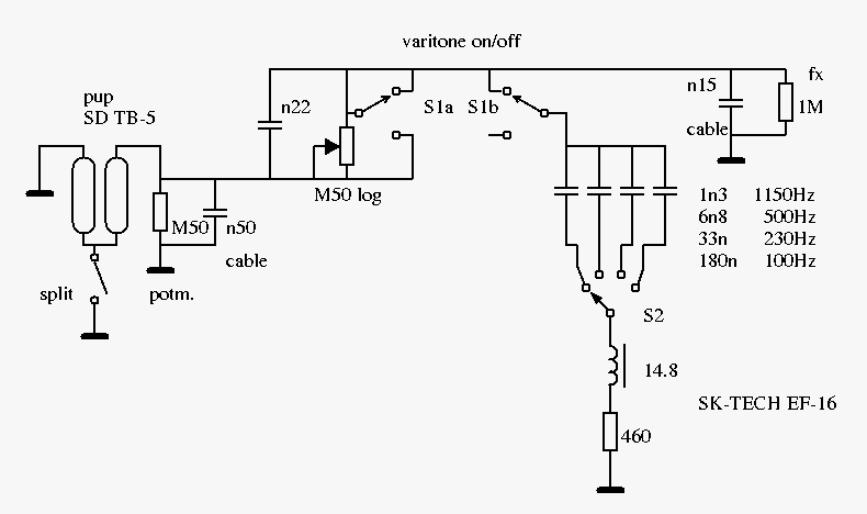
I've built this external varitone box to test the SK-TECH trafo. 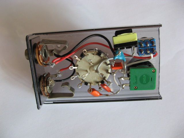 See also the schematic. I performed 2 tests, first one with the configuration as shown in the picture and the second one with the configuration as shown in the schematic. I've modded my varitone box after the first test, but a schematic for test 1 can be obtained from the one posted by shunting M10 and removing M68. 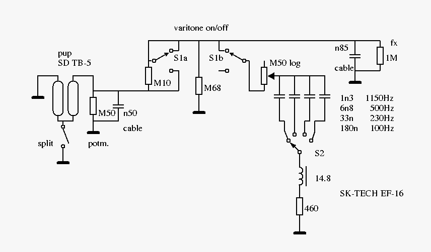 test 1: I can confirm that the SK-TECH trafo does its job well. I've performed the tests with a clean sound through an effects processor with only eq and delay into a headphone amp. The Seymour Duncan TB-5 in series seemed to sound better in all 4 positions with the varitone switched on - less clutter, if that's the word. I was concerned that the varitone would create distorted sounds but that's not the case. The eq is subtle. There isn't much volume loss. The notch is narrow-banded, the tone pot doesn't really function like a tone control but more like a trim pot. Too subtle an effect to waste a potmeter on. The varitone's eq is noticeable in humbucker as well as in split coil mode. test 2: I've added M10 and M68 to make it behave more like a Gibson varitone. I didn't bother to disconnect the volume potmeter and due to the extra cable there is even more loading. With the varitone switched on I noticed more volume loss. (Some of the volume loss is due to the voltage divider and some to the deeper notches.) I expected some muffled tones but that's not the case. I liked the 1150Hz notch in particular. Paul |
|
|
|
Post by newey on Mar 26, 2016 7:32:38 GMT -5
pfp- You work on this is solid, good job! Of course, subjective descriptions like "less clutter" and "subtle effect" wouldn't be necessary if we had some sounds clips . . .  |
|
|
|
Post by reTrEaD on Mar 26, 2016 19:43:59 GMT -5
Nice work, this. The eq is subtle. There isn't much volume loss. The notch is narrow-banded, the tone pot doesn't really function like a tone control but more like a trim pot. Too subtle an effect to waste a potmeter on. The varitone's eq is noticeable in humbucker as well as in split coil mode. Maybe eliminate M68 entirely and move M50 to replace M10, with the pole of S1b connected directly to capacitors? |
|
|
|
Post by perfboardpatcher on Mar 30, 2016 13:50:02 GMT -5
pfp- You work on this is solid, good job! Of course, subjective descriptions like "less clutter" and "subtle effect" wouldn't be necessary if we had some sounds clips . . . Thanks for the compliment, newey!  But I'm already contributing so much! I will be busy for a while modding my spreadsheets and testing and tweaking my varitone circuit. The actual construction of the varitone is relatively easy. Anyone with soldering skills can build a varitone circuit and do a sound test that is more suited to his own needs and taste. A sound clip of my DI-ed high output humbucker with only a little bit of treble boost won't impress nobody, I can tell you that! Nice work, this. The eq is subtle. There isn't much volume loss. The notch is narrow-banded, the tone pot doesn't really function like a tone control but more like a trim pot. Too subtle an effect to waste a potmeter on. The varitone's eq is noticeable in humbucker as well as in split coil mode. Maybe eliminate M68 entirely and move M50 to replace M10, with the pole of S1b connected directly to capacitors? Thanks for your suggestion, ReTrEaD! I will move the 500k pot around and test if it improves the working of the potmeter. But before that I will use the old wiring configuration (#1) to test another transformer I dug up. The trafo looks like a bigger version of the SK-TECH, bigger size and bigger coil, but for some reason the self-inductance is only 1.8 Henries. DC resistance is 300 ohms. I've replaced the cable after the varitone (850pF) with one with a lower capacitance (150pF). 850pF is a ridiculously high capacitance for a 2 meters long cable! I've tested with 3 caps: 120n, 33n, 10n. (Roughly 330, 660, 1150 Herz) Here's another graph with the eq effect when switching on the varitone full on. This is what happens when the self-inductance becomes small, you take a big chunk out of the frequency spectrum. Notch freq. 660 Herz, L=1.8H, C = 32nF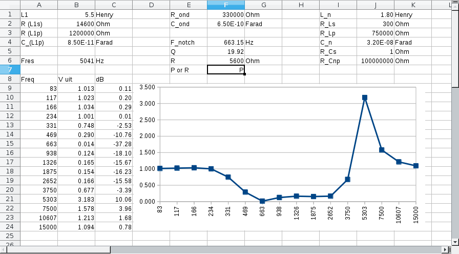 The varitone potmeter works well. For the series HB mode: notch frequencies at 330 and 660 Hz sound good, with the notch at 1000Hz there is too much low mid emphasis to my taste and pick attack is lacking. But it could work for distorted tones. The split humbucker with the varitone engaged gives acoustic highs. Perhaps a small cap between the taper of the varitone pot and earth could be used to keep the resonance peak a bit lower. A way to deal with the varitone's low end is to shunt the cap with a resistor, in this case shunt the 10nF cap with a 68k resistor. Result: +12dB @ 1150Hz, -3.2dB @ 400Hz, -1.5dB @ 50Hz. Not a big improvement. There's still too much signal loss at 3kHz. Notch freq. 1150 Herz, L=1.8H, C = 11nF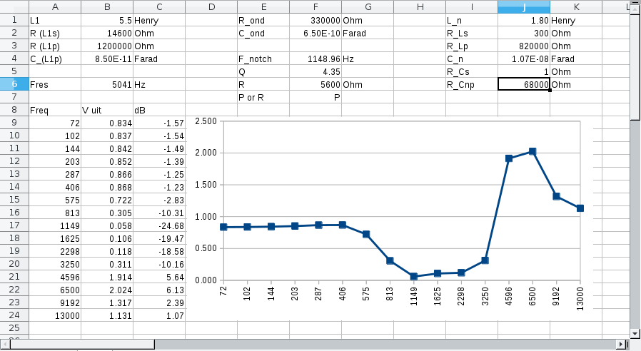 |
|
|
|
Post by perfboardpatcher on Apr 6, 2016 13:27:00 GMT -5
|
|
|
|
Post by JohnH on Apr 6, 2016 16:26:26 GMT -5
This is great work indeed.
So your plots are based on physical test readings, rather than calculations? If so, Id be interested to try to reproduce a couple of them with GuitarFreak spreadsheet. If a reasonable correlation is achieved, then it might be a good tool to investigate different scenarios.
How do you create the input signal to the pickups? Also, what do you reckon the pickup inductance is? How did you work out the values for cable capacitances?
|
|
|
|
Post by perfboardpatcher on Apr 7, 2016 14:08:57 GMT -5
JohnH,
my spreadsheets are merely calculations based on electrical properties of the components which I've measured. So it should be possible to use the GuitarFreak to achieve the same results if there was/is the option to put in all the data. For me personally I have more flexibility if I design my own spreadsheets. Also there is a compatibility problem when using the GuitarFreak in Linux LibreOffice Calc. Drawings aren't converted correctly from Excel into Linux Calc.
I used a multimeter to measure resistances and capacitors (including cables, will also work for piezo discs).
I used a signal generator + scope to measure/determine the electrical properties of the pickup and the inductor.
From then on it's basically creating a spreadsheet with voltages and impedances, voltage dividers, thevenin equivalents.
At this point I'm reworking a spreadsheet to accompany a tweak to the circuitry. I will post the schematic for the old and the new circuit I am experimenting with when ready.
|
|


 But I'm already contributing so much! I will be busy for a while modding my spreadsheets and testing and tweaking my varitone circuit. The actual construction of the varitone is relatively easy. Anyone with soldering skills can build a varitone circuit and do a sound test that is more suited to his own needs and taste.