|
|
Post by christopher on May 8, 2017 12:53:00 GMT -5
So attached to this thread I have a wiring diagram. It's supposed to work like this: 5-Neck Humbucker 4-Neck and Bridge split* out of phase with the neck through a capacitor 3-Neck and Bridge split in series 2-Bridge split* 1-Bridge full The splits marked with asterisks will be run through a resistor to only partially cancel the coil. Does the attached diagram work? I think their might be some errors with the grounding for the split on 3 and 4. The neck will be split to screws and the bridge split to slugs. One last thing, the arrows on the bridge pickup are pointing the wrong direction. Attachments:
|
|
|
|
Post by newey on May 8, 2017 22:16:14 GMT -5
Christopher-
Hello and Welcome to G-Nutz2!
I only had time for a quick glance at your diagram, hopefully I'll have some more time in the next day or two to delve more deeply. But at first blush, I thought I saw some problems at position 3. More to follow, IOW, unless someone else steps up in the meantime.
|
|
|
|
Post by sumgai on May 8, 2017 22:39:38 GMT -5
christopher,
Hi, and welcome to The NutzHouse!
5-Neck Humbucker 4-Neck and Bridge split* out of phase with the neck through a capacitor 3-Neck and Bridge split in series 2-Bridge split* 1-Bridge full My first problem here is, when you say "split", you don't say it for both pickups, it seems to me that you specifically call for the Bridge to be split. But in your diagram, splitting happens for both pups in various positions (or it's supposed to anyways), and since it's not consistant with your truth table (quoted above), I'd like more clarity - does split mean both pickups each and every time, or does it mean Bridge pickup only?
Next, you mention OoP (Out of Phase), but that can't happen with the current wiring - you need to make sure that what is normally the 'hot' lead is instead going to ground, and that what's normally supposed to go to ground instead goes to the output terminal (where the 'hot' normally goes). Although.... by inserting a capacitor in the circuit, did you intend to mean "half out of phase"? That's a different type of wiring, and before we go there, we'd like some clarification on this too, please.
There there's this:
Excuse me?! All you've accomplished is to load the pickup's coil such that it won't produce it's full potential. Around here, we call that 'tone robbing'. Trust me, it won't sound good, and it will definitely upset the tonal balance between the two pickups. But if that's what you want..... Sorry, nope. And, there sure are. Some errors, that is. And they aren't limited to just Pos 3 & 4, sorry to say. Too much information. The circuit doesn't care about screws and slugs, and you shouldn't either. What's more important is that you engage the correct pair of coils that will still cancel hum. It's a known, and hard-learned fact that not all pickups are created according to Hoyle. Even from the same company, what is alleged to be the 'North' coil, with such-and-so a wire called the 'start', that can vary over time, or even in the same batch. Someone who's new to the job, or had too much caffeine (or something else, at lunch break), anything can get in the way of quality control, and the next thing you know, crap happens. Don't take the manufacturer's word for it - test it for yourself, before installation. See my point above - the circuit doesn't care about arrows and such, and you shouldn't either.
But not all is lost. Actually, once we've gotten our terms straightened out, I think we can modify your diagram to make it all come out the way you want it. The ball is in your court. 
sumgai
|
|
|
|
Post by JohnH on May 9, 2017 15:26:14 GMT -5
Im having trouble following the diagram today (its very early here). Where do you take the output from?
It looks like you are setting up a particular set of tones that you have tried before, which if so is all good.
I get the part-bypassed idea with the resistor. I like that too when splitting a bridge PU, it keeps a little thickness in the sound. I use a 0.047uF cap instead of a resistor on my LP, which is a good alternative.
|
|
|
|
Post by christopher on May 11, 2017 16:59:39 GMT -5
Thanks for the help, seeing as few people are on here I'm surprised I got help this fast.
Since my diagram doesn't work, could one of you come up with one that does? And if you want to draw this in just for your own sake, it's master volume and master tone. And just to clarify here are the positions:
5-Neck Humbucker
4-Neck split and bridge split out of phase in parallel with the neck through a capacitor(with resistor for split)
3-Neck split and bridge split in series (no resistor)
2-Bridge split (resistor)
1-Bridge Humbucker
And Sumgai, usually I agree with you on the fact that which coil you leave on when you split doesn't matter, but these are hybrid pickups I made and if you split to the wrong one it will be weak (these were in a guitar with a switch to switch between coils before this one).
|
|
|
|
Post by sumgai on May 11, 2017 21:20:49 GMT -5
christopher,
First, there are many participants here, but most of them feel they are being polite by letting one of us "core" members take the lead. That's all the more true when there are problems with a circuit, big or small. Still, about a dozen of us are with you, and we'll get you where you need to be.
However, we do 'prefer' to teach you how to do it yourself, instead of just handing you a piece of cake. That said, I can whomp up a drawing in a few hours, please stand by.... (The wife has put the arm on my time this evening, and Lowered help the interwebs that get in the way when she's in Command Mode! I'll need to wait until she's toddled off to bed. After that, the computer is all mine, hehehe.)
Care to share anything more about your self-built hybrid pickups, they sound interesting....
And even for unmatched coils, the criterion is that the two chosen coils don't hum, regardless of position. Or in your case, regardless of signal strength. But I'm sure that by now, you have already figured out that a pickup can be rotated such that the desired chosen coil is in the desired position. (Unless you built yours really odd-sized/odd-shaped!!)
Come to that, I'm not sure as to exactly why you want a resistor in the circuit, but so be it, I'll include it as you've shown it in the attachment to your first post.
sumgai
|
|
|
|
Post by newey on May 11, 2017 21:45:38 GMT -5
I had a go at a diagram for this but I won't swear that it'sright with any great confidence. I am also still not clear on exactly what this means: So I've got parallel out-of-phase at position 4, with the neck split coil through a cap to ground, but with no resistor, since I wasn't sure from your description which coil(s) were supposed to get the resistor. But maybe this can at least serve as a template. It can probably also be simplified. 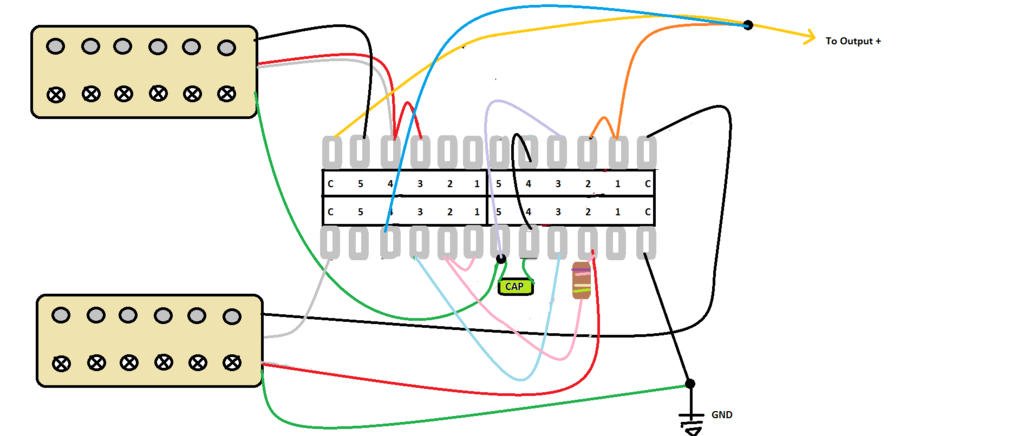 The wire colors are Seymour Duncan color coded, which seemed to correspond to what you had for your custom pups. Green/red is the screw coil (which is "South" in the SD world), black/white is the slug (SD's "North" coil)- not sure if that's the same as yours or not. As JohnH mentioned, some testing may be in order. Also note that the white wires are shown in light gray for clarity. |
|
|
|
Post by christopher on May 12, 2017 7:02:38 GMT -5
Thank you for your help, this is actually more information than I usually get on larger forums. Newey, just to clarify, the resistor is in series with the coil that is being shunted to the ground on both the neck and the bridge of position 4. The reason I'm doing this is to give less of a volume drop in the 2 and 4 positions, I don't want the resistor in position 3, as the pickups are in series anyway. The capacitor is so that the low end gets blocked from the signal so that they won't get canceled out when it's out of phase with the bridge. And since you took an interest in my pickups here they are: 59/Jazz (59 slug/ Jazz screw) hybrid with a A3 magnet, it's really good for cleans, with harp-like bass strings and chimey treble strings. The bridge pickup is a 59/78 (59 screw/ 78 slug) hybrid with an A2. Given that it's coils are mismatched and that the 78 is pretty bright as it is, the tone control is really important for this pickup. It's very versatile for different types of rock, able to go from AC/DC to Van Halen when full and gets pretty good p90 tones if splot with a resistor. I like them, though the 59/78 might be better with 250k pots.
|
|
|
|
Post by sumgai on May 12, 2017 11:51:44 GMT -5
christopher,
I'm sorry to have to say, you haven't fully answered my question about phasing. Did you mean a fully out of phase condition on Position 2, regardless of the capacitor? Or did you mean that the capacitor will impart a tone that we call "half out of phase"? As I read it now, you wish for both conditions, is that correct?
If so, I'm gonna need a bit more time. I still think I can do it, but it won't be straightforward. And I might be pissing up a rope for all I know, I need to do the design step by step, from start to finish. As it stands now, I know it can't be done using your original diagram as a start, that much is clear.
Punt, the ball's in your court!
sumgai
|
|
|
|
Post by christopher on May 12, 2017 13:31:29 GMT -5
Position 2 is the bridge split. Position 4 is the one that is the Bill Lawrence half out of phase. That would be the neck and bridge totally out of phase with each other. There is a cap between the hot from the neck to what ends up as the volume. They will also be partially split with the resistor between the coils. I hope this cleared it up.
|
|
|
|
Post by sumgai on May 12, 2017 18:08:54 GMT -5
That would be the neck and bridge totally out of phase with each other.... I hope this cleared it up. Indeed it did, thank you.
I have an idea. It may not be a good one, but at my age, having any kind of an idea is good enough reason to make a special entry in my diary! 
sumgai
|
|
|
|
Post by christopher on May 12, 2017 19:12:55 GMT -5
Funny, I've got the opposite problem, I'm at that age where I have a lot of ideas, but rarely any that are as good as I think they are when I come up with them.
|
|
|
|
Post by sumgai on May 13, 2017 11:10:04 GMT -5
christopher,
Still working on it. Real-life keeps intruding on my cogitations. I've probably got it, but I think there's one issue yet that needs careful inspection, before releasing it into the wild.
Hang in there!
sumgai
|
|
|
|
Post by sumgai on May 14, 2017 1:30:17 GMT -5
christopher, OK, let's see if this image trips your trigger: (Tip: right-click and open in a new window/tab, then you can view both text and image at the same time.) 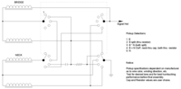 Besides the notes on the drawing itself, I want to point out something. Long time readers here will recall our numerous discussions and ruminations about the so-called 'hanging hot' issue. Cutting to the chase, I can't get away from the issue with your circuit. I've solved the five combinations you asked for, but no matter how I slice it, there will always be a loose coil, ready to induce noise into your signal. Thinking on that, I decided to experiment, or be more correct, I'm going to "let" you do my experimenting for me. Here's the skinny: In Pos 5, Neck only, the Bridge is still connected to the outgoing line. In fact, both Bridge coils are hanging from hot at this point. It may look like I could simply connect/disconnect the Bridge 'hot' lead with the upper-right pole of the superswitch, but then in Pos 3, I'd have the Neck lower coil in parallel with two 'upper' coils that are in series - not desired. So.... With a single coil pickup it is trivial to remove the hanging hot - simply short the coil's negative lead to the hot lead, and you're done. Here, I have two coils, in series. The negative end goes nowhere, thus rendering the pair as hanging from the hot signal out line. But, this is a humbucker - that's something I've not had to deal with before, nor do I recall anyone else here successfully overcoming a hanging hot on a humbucker. I suppose I could be forgetting someone/something, but you and I are here and now. What I wish for you to do is to wire up the system as shown, and test carefully for any extraneous hum while in Pos 5, Neck only. If there is more hum than you can tolerate, do this: hook up a short jumper cable from the 5th position terminal on the upper left Pole to short out one of the two coils. It won't matter which one, we can't short them both, or we'd never have any sound out of the pup at all.  But my hope is, a humbucker will actually "self-annhilate" any hum that might otherwise get into the signal path, so I left that jumper out. A report on your findings would be nice, please.  Also, sound clips of each of the positions would be nice. You can post them either here or in the Sound Samples forum, as you wish. HTH sumgai |
|
|
|
Post by newey on May 14, 2017 6:52:53 GMT -5
Sumgai is right, I too couldn't see how to do this without having the neck "hanging from hot".
I traced through his schematic, it looks good. Somewhat of a different approach than I took but as I said, there's a few ways to do this. Now you have to either translate sg's schematic into a wiring diagram, or alternatively, wait for someone to vet my diagram and insert the resistor .
|
|
|
|
Post by christopher on May 14, 2017 8:05:53 GMT -5
Thanks, I should be able to wire it up later today. And I was thinking as I read your post that a humbucker should still be able to buck hum when it has a "hanging hot". I'll report back as soon as I'm able. I did shield my pickups and pickguard though, so there might be less noise anyway. Also, I'm not used to diagrams with the pickups written in the way that you have them, what are the wire colors for this diagram with Seymour Duncan? I take it that this diagram has it so that the bridge splits to the slugs and the neck to screw?
And those sound samples might not be the greatest, I'm one of those guys who spends all his time modding instead of practicing, and it's gonna be on a cell phone.
|
|
|
|
Post by JohnH on May 14, 2017 15:27:02 GMT -5
Just hold the wiring!! It's great to see the schematic drawing. I'm thinking the resistor part is not doing what christopher intended though. This is how I read the desired 5 settings, which all make sense to me:  |
|
|
|
Post by christopher on May 14, 2017 17:32:10 GMT -5
Sorry, I didn't see your post before I wired it. The only position that works is #1, but that's probably my fault, I was working with a switch that had already been used. I'll try it again with a new switch as soon as the parts ship in. Another thing to consider that I didn't notice until today, the magnet in the bridge is in backwards.
|
|
|
|
Post by JohnH on May 14, 2017 17:37:07 GMT -5
Ok. It would be good if you can check my sketch to see if it shows the settings that you are after
|
|
|
|
Post by christopher on May 14, 2017 18:28:52 GMT -5
That is correct. I would also just like to remind you that the magnet for the bridge is in backwards, so the hot and ground would be reversed.
|
|
|
|
Post by sumgai on May 14, 2017 22:44:21 GMT -5
christopher, .... what are the wire colors for this diagram with Seymour Duncan? I take it that this diagram has it so that the bridge splits to the slugs and the neck to screw?
As I noted before, color codes and such only get in the way when designing a circuit meant to solve a problem in logic. By focusing on this key element, anyone reading this in the future who might say "hey, that's for me!" can supply their own specifications for wire colors, winding directions, screw vs. slug, magnet orientation and mounting requirements. That makes this a rather generic drawing, the exact purpose of a schematic.
Having said that, you earlier noted that the pups are 'custom built'. I have no idea which coil from which original pickup has what wire colors, whether it's a screw or slug, which one might be start or finish, etc, you get the idea. Perhaps with a stock pickup I could dope it all out, but at this point, I have to defer to your deeper knowledge of how the parts and pieces were re-assembled into the custom units. Sorry 'bout that. 
HTH
sumgai
|
|
|
|
Post by sumgai on May 15, 2017 0:35:48 GMT -5
Just hold the wiring!! It's great to see the schematic drawing. I'm thinking the resistor part is not doing what christopher intended though. This is how I read the desired 5 settings, which all make sense to me: John,
Thanks for the second pair of eyes.
In Pos 4, you determined that the Neck positive is going directly to ground, and that the Neck negative goes through the cap to the upper-right switch pole. Sadly, I see it differently. The positive lead goes through both the cap and the resistor, then to terminal 4 of the lower-right pole and thence to ground. The negative terminal goes directly to terminal 4 of the upper-right pole. The Bridge positive lead goes where expected, and the negative lead goes through the resistor, but not the cap, to terminal 4 of the lower-right pole, and thence to ground. The coil-split leads for each pickup go nowhere.
Taken altogether, this yields B + Noop, with a cap diminishing some of the lows for the Neck, and a shared resistor loading both pickups on the same signal polarity.
For Pos 2, you see the resistor as shunting the lower Bridge coil. In my drawing, Pos 2 of the upper-left pole clearly shunts the Bridge lower coil, as it connects the coil-split lead to terminal 2 of the lower-right pole, and thence on to ground.
christopher, unless I mis-read your updated intent, then I'm pretty sure this solves your logic puzzle. Any questions?
sumgai
|
|
|
|
Post by JohnH on May 15, 2017 2:56:38 GMT -5
Sumgai, I think the main difference between what I thought and what you drew is that in positions 2 and 4, your drawing has the whole signal from everything active, going through the resistor to get to ground. I dont think that is what is wanted here but chris can best comment. I think the idea is to partly bypass one bridge coil in these positions, which makes a brighter sound compared to full humbucker, with a bit of added low end.
|
|
|
|
Post by christopher on May 15, 2017 4:15:56 GMT -5
JohnH is right on this one, the resistor is meant to be in series to ground on the shunted coil as to let some of the signal pass through.
|
|
|
|
Post by sumgai on May 15, 2017 12:45:37 GMT -5
JohnH is right on this one, the resistor is meant to be in series to ground on the shunted coil as to let some of the signal pass through.
So help me Gawd, I'm having a dystopian moment here.  I can't figure how a coil is shunted (in parallel), yet the shuntee (the resistor) is in series to ground? WTH??? Are we perchance meaning that the resistor is in series with the 'upper' coil, and it is shunting the 'lower' coil? I can't figure how a coil is shunted (in parallel), yet the shuntee (the resistor) is in series to ground? WTH??? Are we perchance meaning that the resistor is in series with the 'upper' coil, and it is shunting the 'lower' coil?
That's question number 1. Question number 2 is:
From the updated specs: Quesition number 2 is: should I have taken that to mean that only the Bridge has the shunting resistor, and not both Bridge and Neck? That wasn't made clear, and in fact, the original diagram shows the shunting resistor on the coil-split leads for both pups. How was I to know? I mean, my only clue was that both christopher and John recently spoke in singular, and not in plural... that lead me to wonder if I misinterpreted the original intent. I'm sure everyone can understand why I'm now a bit shy about making any further changes - detailed instructions are somewhat lacking.
Upon further cogitation: I see now that why I immediately assumed that the original diagram had at least one problem. In seeing that both pickup lower coils were grounded, and that both coil-split leads were going to ground through a capacitor, I jumped to the conclusion that series was not going to happen, period. I dropped all further analysis, sorry to say. Perhaps the fault here is mine.....
And question number 3 is: are both Bridge coils expected to be fully engaged in Pos 2? And ditto for the both pups in Pos 4?
I'm not ready to give up just yet, there are still some tricks left in this old dog. He just needs the right amount of doggie treats to encourage him, that's all.
sumgai
|
|
|
|
Post by christopher on May 15, 2017 16:03:39 GMT -5
I'm sorry, I'm new with all this electrical terminology. I'll try to explain it in a better way:
1- Bridge, both coils in series
2- Bridge, Slug coil in series with screw coil (the screw coil is shunted through a resistor, the slug coil is not, referred to as partially split)
3- Neck split with screw coil active in series with bridge split with slugs active (no resistor in circuit)
4- Neck partially split in parallel and out of phase with bridge partially split (the neck goes through a capacitor)
5- Neck, both coils in series
The answer to question one is yes, the electrical path goes from ground, to the coil that is being shunted, through the resistor, through the active coil, to the output. All of that is, of course, in series.
Question 2: The shunting resistor is active on both the bridge and neck in position 4. It is not active on either in position 3. And it is active on the bridge in position 2.
Question 3: If by both bridge coils are active in position 2 (and both pups in positon 4) you mean that both contribute to the signal, then yes. But in both the positions they are partially split, so one of the coils in whichever pickups are in those two positions will be extremely low on output.
|
|
|
|
Post by JohnH on May 15, 2017 16:28:07 GMT -5
I'm now much more confused! (though actually I didnt think I was confused before!).The last set of descriptions are not what Id thought.
Unless sumgai sees it all clearly now, Id suggest sketching seperate diagrams of each setting without switches, similar to my sketches above. Note: one key thing on tbose is a + symbol to indicare which side of a coil would go towards hot if it was in a standard wiring.
But I still think that the way I sketched the settings is what you probably might want. If so, it can be done. There are a few hanging connections needed but not a big problem particularly in covered pickups.
Also i was wondering if you have tried the position 2,3 and 4 sounds before? I think they should be good though I havnt tried that out of phase recipe myself.
|
|
|
|
Post by christopher on May 15, 2017 16:44:58 GMT -5
|
|
|
|
Post by sumgai on May 15, 2017 19:43:18 GMT -5
christopher,
Your latest descriptions are good as gold for me, thanks a bunch. And it's not your lack of 'electrical terms expertise', we're all using standard English here, nothing to get excited about.
John, I can see from the description immediately above, and from the original diagram, just what christopher is trying to accomplish, no problem. Your suggestion about separating out each 'tone path' as a way to illustrate the switching logic Truth Table has great merit. I think we should all push a little more for that kind of descriptive drawing in showing how something complicated is intended to work. In my drawing's next incarnation, I'll do that part too.
Please stand by, this will take a bit more time than a simple wave of the Magic Wand. BRB......
EDIT: John, I think that Position 3 is merely a straightforward N * B combo, with single coils instead of full humbuckers. This shouldn't load the output so badly that the tone would suck, but it won't have the expected sparkle we'd usually find, being series instead of parallel and all.
sumgai
|
|
|
|
Post by christopher on May 15, 2017 20:33:58 GMT -5
I forgot to mention, since the bridge magnet is in opposited polarity as the neck, if the diagram were to be drawn so that both the pickups would be split to the screw coil and then I switched the hot and ground wires, that would make it so the bridge is back in the correct phase for positions 3 and 4 and make it so that the bridge splits to the slug. Forgive me for the run on sentence, it almost pained me to type it.
|
|


 But my hope is, a humbucker will actually "self-annhilate" any hum that might otherwise get into the signal path, so I left that jumper out. A report on your findings would be nice, please.


 I can't figure how a coil is shunted (in parallel), yet the shuntee (the resistor) is in series to ground? WTH??? Are we perchance meaning that the resistor is in series with the 'upper' coil, and it is shunting the 'lower' coil?