cmscss
Meter Reader 1st Class
 Ad-free Angel
Posts: 78 
Likes: 2
|
Post by cmscss on Dec 13, 2017 20:25:48 GMT -5
Hi There, A few years ago a posted the attached schematic for review and have just got round to wiring it but have the following issues: - The neck pickup doesn't work
- Can't test parallel/series & pop because of the above
- The volume knob doesn't work
I've checked the wiring against the schematic several times and have tried different pickups just incase but no joy. I'm very green when it comes to guitar wiring (I've build a few guitar pedals) so am unsure what I might be doing wrong. Any help or pointers in the right direction or a trouble shooting process would be much appreciated.  Cheers Ben |
|
|
|
Post by sumgai on Dec 13, 2017 22:57:07 GMT -5
Ben, Somehow your screen name seems famailiar.... Your diagram doesn't appear to have any problems that I can see, so I have to assume that one of two things is at fault here (or both of 'em are): - dead Neck pickup - bad solder joints Since you've tried other pups, we should be able to eliminate the first culprit. Added into the mix is a non-functioning Vol pot. That's easily tested (unsolder one wire and check it with a meter), but I still like the idea of bad solder joints. While you're at it, you could/should test every switching component for continuity. As other members here will tell you, sometimes a new component arrives on your workbench already kaput. Not often, but then again, Murphy has a law named after him for a very good reason!  Action items for you: - re-heat all solder joints, inspecting for any tiny 'solder bridges' that might cause a short - test each component separately (unsoldered from the circuit) for proper operation After all that, and it still doesn't work, then go back to basics - install and test one - and only one! - component at a time. One pickup. Works? Good, now put in the Vol pot. Still works? Good, now put in a switch. (Polarity, at this point) Still works? Good. You get the idea here, it's nothing more than building blocks - one at a time, over and over and.... If at some point a failure is encountered after several successes, then you know exactly what to investigate, right? OK, that's all I have for you, good luck! HTH sumgai |
|
cmscss
Meter Reader 1st Class
Ad-free Angel
Posts: 78
Likes: 2
|
Post by cmscss on Dec 14, 2017 0:28:06 GMT -5
Awesome reply, very much appreciated.
Will do as you suggest and report back, cheers
|
|
|
|
Post by sumgai on Dec 14, 2017 14:14:06 GMT -5
Ben,
I just had another thought.... (And this is for everyone reading, not just you.)
In the big majority of cases, the 3-way pickup selector has the common terminals for each of the two poles on opposite ends. (This is in contrast to those that look like printed circuit boards, where the commons are usually in the center of a single line of terminals.) But the rub is, a few manufacturers have put the commons on the other end of the string of terminals from what we normally expect.
To wit: if we observe a switch from the backside (the terminal side, not the lever side), and if we orient it 'horizontally', we would ordinarily expect to find the common terminal for the lower section on the far right, and for the upper section on the far left - this is the case for your diagram. However, like I said, there are switches for sale out there that are lined up in the opposite direction. When I said that you should test each of your switches to make sure they are operating as expected, this particular test is one that I had in mind. If you've somehow gotten a switch of the opposing direction, then your test will reveal such, and you can make wiring changes as necessary.
BTW, I must commend the author/designer of that diagram for figuring out how to eliminate potential hum from a "hanging hot" in Pos 1.
And.... In thinking about that congratulatory note, I realized something else. (Again, for all readers, not just you.)
<theory discussion> (already well hashed out, but renewed here for reasons to follow) In a two pickup scenario like this one, a Series/Parallel (S/P) switch can be located in either of two places in the circuit - before the pup selector or after. In the second option, that's called a "Master S/P" switch because it overrides the pickup selector - when Series is chosen, it won't matter what the pickup selector is set to, both pickups will be turned on, in Series. When, like in this circuit, it's active only when the pickup selector is in Pos. 2, then it's a subservient S/P switch - it's only active in that one position.
The reason to make this distinction is that both pickups on in Series is usually a bit louder, and not quite as schrill as the Bridge alone. For some players, that makes the combo a desirable "now I'm gonna blast it out" setting, leaving the pickup selector in place for, perhaps, a less strident rhythm setting. It is a matter of personal choice, but I think it's good to have options, I'll bet most players will agree.  </theory discussion>
And for the record, did you consider the use of a so-called Fender "Baja" switch? This is a four-position lever-type switch that lets a two-pickup guitar have both series and parallel on one switch. Intuitive, less messing around with multiple switches while playing, less trouble and frustration on the workbench trying to hook it all up, less expensive, I could go on, but... 
Alright, that's enough for now! 
HTH
sumgai
|
|
cmscss
Meter Reader 1st Class
Ad-free Angel
Posts: 78
Likes: 2
|
Post by cmscss on Dec 14, 2017 19:53:00 GMT -5
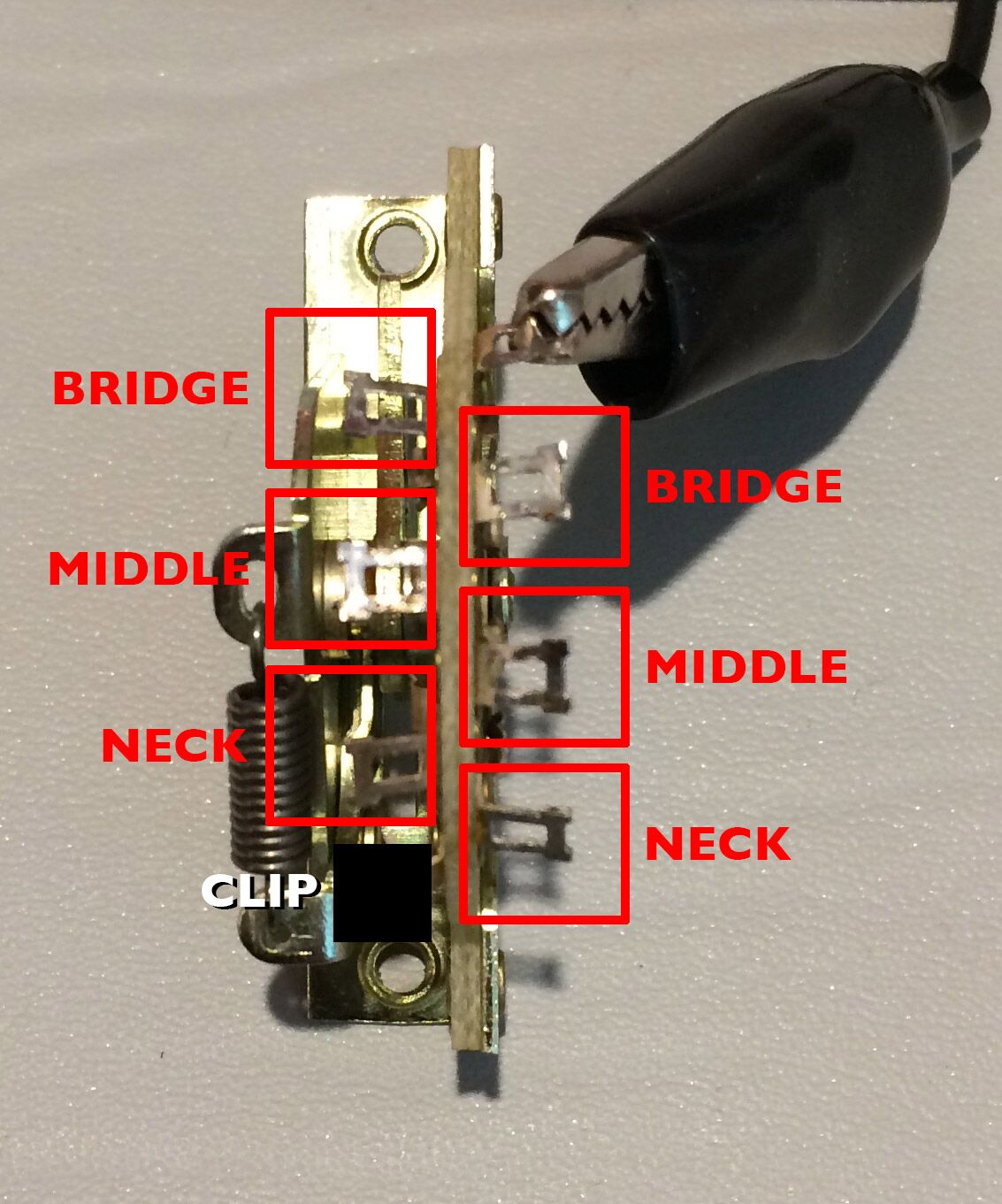
I've started testing things, both pickups read 6K Ohms but I'm having trouble with the 3-way switch. Not sure I have it orientated correctly but how would I test the switch by itself in a standard config (I've removed all the wiring). This is what I'm doing...  Questions: Questions:1. In the image, I have the black lead on the volume lug and the red lead on what I understand to be the bridge pickup (in a standard config). I get continuity with the selector in the bridge position which is correct - right? 2. But with the selector is in the middle position I don't get continuity, should I? 3. My understanding is that the bridge pickup is the first lug opposite the volume (closest to the start pop the spring)? When I place the hot lead there I don't get continuity in any position. Sorry for the simple questions but any pointers would be much appreciated. Cheers |
|
cmscss
Meter Reader 1st Class
Ad-free Angel
Posts: 78
Likes: 2
|
Post by cmscss on Dec 14, 2017 19:54:15 GMT -5
Ahhhh, sorry, didn't refresh before posting and have only just seen your new post - will read now.
|
|
|
|
Post by sumgai on Dec 14, 2017 20:41:35 GMT -5
Ben,
We're almost doing this in real-time! 
To directly answer your questions:
1) No, not for your switch, see my comments below. But as to the continuity test, yes, the two farthest apart terminals are connected, and in your case, that is designated as the Bridge pickup.
2) If I have read your intent correctly, then no, there should not be continuity.
3) You don't get continuity to the other terminals because that's not the common terminal, see my comments below.
In essence, you would be served best by dropping such labels as "volume terminal" and "bridge terminal". This is because there is no one "standard" way to hook up the switch to pickups or controls or to whatever the player wants - you can do just about anything you can imagine! (If you want to refer to the Fender way of hooking things up and call that "standard", that's cool, but it's not the only way. But for comparison here, we need only look at any Fender diagram using this switch, and we'll see that the pickups are never wired to a common terminal, only to one (or more) of the individual terminals. Just about every time, in Fender's case, the common terminal goes to the Volume and Tone controls.)
Also of note however, is that we prefer the term "common terminal" to denote the terminal that makes contact with the other terminals, as the switch lever is moved. In the case of your picture, you have the red clip on the common pole. Accordingly, as the lever is moved to one end of travel, the circuit will be completed from the common to the terminal where you have the black clip. Staying with the naming convention in your diagram, Pos 1 (Bridge) would connect the black clip to the red clip - and no other terminal is connected to either of those two.
HTH
sumgai
|
|
|
|
Post by reTrEaD on Dec 14, 2017 20:53:57 GMT -5
To wit: if we observe a switch from the backside (the terminal side, not the lever side), and if we orient it 'horizontally', we would ordinarily expect to find the common terminal for the lower section on the far right, and for the upper section on the far left - this is the case for your diagram. Not sure there's a to wit or a two wit or a full wit or 50% of a wit here. If we're talking about 3-way switches found on Fender® Telecasters . . . When the switch is oriented horizontally and viewed from the wafer side, the poles (commons) will follow your verbal description exactly. But . . . The offset of the lugs is opposite from the way it's shown on Ben's drawing. The pole on the lower right should not be shifted to right of the last lug in the upper row (as drawn). Instead it should be to the left of the last lug in the upper row. Maybe this switch is different. Careful visual observation will reveal which lugs are the poles. For instance:  The pole on this side of the wafer on the right |
|
cmscss
Meter Reader 1st Class
Ad-free Angel
Posts: 78
Likes: 2
|
Post by cmscss on Dec 14, 2017 21:01:03 GMT -5
OK, I'm way out of my depth! 1. The reason I went for seperate switches is because live, I find selector switches too fiddly. So happy with this setup. 2. I much prefer your idea of a Master S/P switch which means I could switch to a boosted sound from any pickup position right? 3. Can I do the same thing with the phase switch, can you use one switch to switch in both pickups out-of-phase from any pickup position? 4. I'm lost sorry. Would it be possible to help outline the following...
- How to test and understand what kind of switch I have (which terminals are what)?
- How to modify the diagram to have a master S/P switch?
- If possible, one switch out-of-phase from any pickup position
Have removed the switch, here are some shots.
www.dropbox.com/s/r0zz2yzc4gru30n/3-way-switch-1.JPG?dl=0
www.dropbox.com/s/3ns37k5gq52a6q3/3-way-switch-2.JPG?dl=0
Thanks for all your help, you guys are awesome.
Cheers
Ben
|
|
|
|
Post by sumgai on Dec 15, 2017 2:09:26 GMT -5
Ben,
This has to be quick, I'll be gone for the day tomorrow, and need to make preparations for an early start.
(EDIT: Paragraph removed for lack of clarity. Further explanations below.)
As noted, I can't spend but another few moments on this for you just now, but since reTrEaD has joined the conversation, I think if you ask him nicely, he'll be able to point you in the right direction concering how to redraw the diagram for your switch, and how to change things around to implement a Master S/P circuit. Either way, I'll be back online Saturday morning. Good luck!
HTH
sumgai
|
|
cmscss
Meter Reader 1st Class
Ad-free Angel
Posts: 78
Likes: 2
|
Post by cmscss on Dec 15, 2017 21:26:41 GMT -5
|
|
|
|
Post by sumgai on Dec 16, 2017 3:09:45 GMT -5
Ben,
I'm back from my short trip, but I'm ready for some sleep. (Advice: don't grow old, it's hell on your body!) I saw your latest image, and it's good to have those labels. I'll see what I can draw up for you tomorrow morning - hang tight!
sumgai
|
|
|
|
Post by reTrEaD on Dec 16, 2017 10:50:27 GMT -5
Ben, you displayed a willingness to put some effort into this process. We like that. Over the next few day, I think we can sustain a dialog that helps you get where you want to go. This is likely to include several Nutz members. Your switch is a CRL but the offset is different from what I've seen in the past. The image you just posted does a fine job of defining how it works. The image I'll post now defines how it fits into your original drawing. 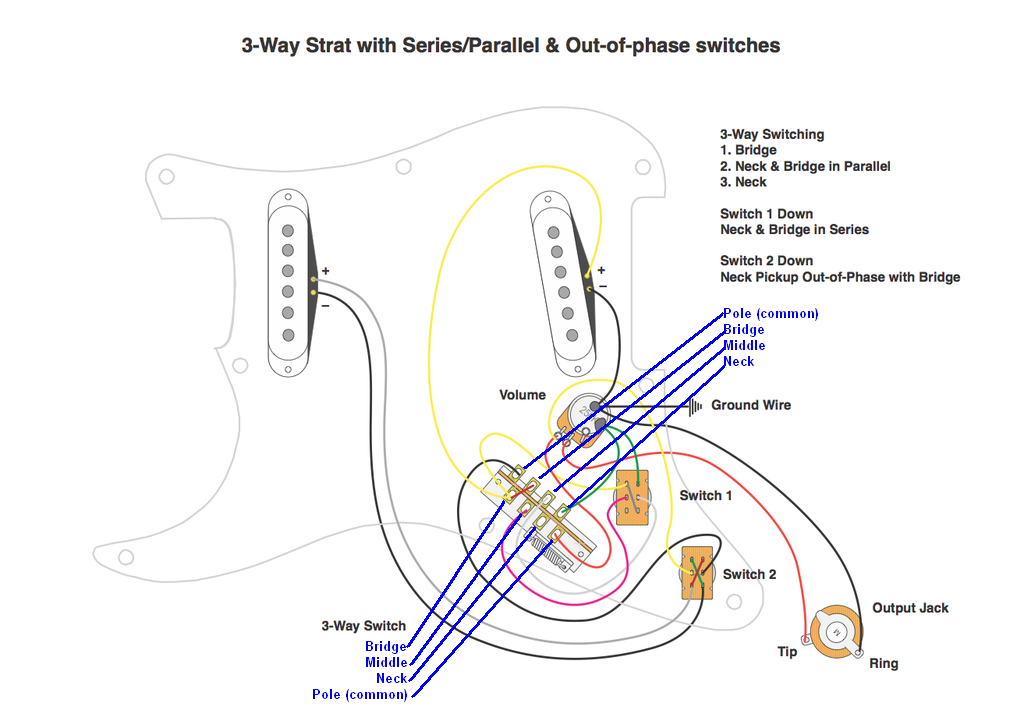 It seems we're likely to abandon the original scheme though, based on the questions you asked in a recent post. I'll try to answer them in my next post. |
|
|
|
Post by reTrEaD on Dec 16, 2017 11:46:06 GMT -5
OK, I'm way out of my depth! No worries. We'll take this a step at a time. You'll learn as we proceed. 1. The reason I went for seperate switches is because live, I find selector switches too fiddly. So happy with this setup. Okay then. A 3-way plus two mini-toggles will be the plan. 2. I much prefer your idea of a Master S/P switch which means I could switch to a boosted sound from any pickup position right? Let's not call it a Master S/P switch. That doesn't fully describe what it does. More like Series Override. Two pickups in Series, instead of Whatever is selected by the 3-Way. And yes, that will get you the slightly stronger and darker sound of two pickups in series with the flip of the minitoggle, regardless of what is selected by the 3-Way. However if the phase switch is in the Out of Phase position, Series out of Phase is a bit weaker than Bridge-only or Neck-only. 3. Can I do the same thing with the phase switch, can you use one switch to switch in both pickups out-of-phase from any pickup position? If we have enough poles, anything is possible. But in this case, it would take an awful lot of poles. Your original plan had the capability of providing six choices. Neck-only Bridge-only Neck and Bridge in parallel Neck and Bridge in series Neck and Bridge in parallel (Out of Phase) Neck and Bridge in series (Out of Phase) (Neck-only Out of Phase will sound the same as Neck-only so we don't count that as a choice) If you choose to make your phase switch a "two pickups out of phase override" you would need to decide whether the pickups are series-out-of-phase or parallel-out-of-phase. That would limit your choices to a total of five. Not saying that is a bad thing. Just that it is what it is. Series-out-of-phase would be preferable to parallel-out-of phase. But the choice is yours. ALSO worth considering. . . Instead of just out of phase, your phase override might be designed around a Half-out-of-Phase configuration. Parallel Half-out-of-Phase is an interesting choice. It doesn't castrate the bottom end. For instance, you could have the full bottom of the neck combined with the out of phase bridge coupled through a capacitor. Only the mid and upper frequencies would have the potential to cancel. In any case, a two-pickups-out-of-phase override switch would require four poles. So you would need to upgrade from a DPDT mini-toggle to a 4PDT minitoggle. Also, the two-pickups-out-of-phase override switch would take precedence over the two-pickups-in-series (in phase) switch. Unless we also upgrade the two-pickups-in-series (in phase) switch to a 4PDT switch. --------- Personally, I favor staying with the two DPDT switches, phase switch for the Neck pickup, and Series Override switch. But the choice is yours. We'll move according to your preference. |
|
|
|
Post by sumgai on Dec 16, 2017 13:06:21 GMT -5
Ben,
'TrEaD has pointed out some worthy topics for you to consider. But for me, and most others, the name of the game is KISS - Keep It Simple, Stupid. As you don't like "fiddly", then stick with your original plan: 3-way, phase and Series Override (reTrEaD is correct, my use of "Master" was incorrect).
Sadly, as another new member here was the guinea pig to find out, we have now hit a limit in our attachments*. We can still link to images on other websites, but the market forces are moving to disallow this practice (as a freebie, at least). It may be next decade, or next week, but it will happen. For that reason, the Staff here in The NutzHouse is discussing our next move. More on that in a new thread to come soon.
But the upshot is, we can't directly attach anything to illustrate how to hook up everything discussed so far, so it'll be a "few" moments before a suitable diagram can be displayed here, sorry to say.
As to a "phase reverse override" switch, I'd not be so hasty - there will be times when having both the series and the parallel OoP options onboard will be nice. And since you already have the switch mounted anyway, why limit its usefulness to just one or the other?
HTH
sumgai
* Unbeknownst to newey or myself, ProBoards very conveniently "forgot" to display (in the Administration panel) the little factoid that there is a limit to attachments. In fact, neither of us can get into the section of Administration Settings that would, allegedly, allow us to upgrade and get past this snafu.
|
|
|
|
Post by reTrEaD on Dec 16, 2017 13:58:51 GMT -5
As to a "phase reverse override" switch, I'd not be so hasty - there will be times when having both the series and the parallel OoP options onboard will be nice. A selling point, but maybe a small one. Depends on the individual. I never bother with OoP anyway so my opinion shouldn't carry much weight for a decision made by someone who likes that stuff. As far as the fully out of phase configurations, it seems Series out of phase tends to be much preferred over Parallel out of phase. By most folks, anyway. Using the simpler arrangement of a standard phase switch on one pickup keeps the wiring strategy simple so that's the big plus - in my opinion. YMMV. Ben, Here's a drawing which displays the strategy of a Series Override with a standard 3-way pickup selector. It applies to a Tele, LP, or any two pickup design where the 'both' selection is Parallel. The selector is just represented by a box. Specifics will depend on the particular switch being used. The dots represent the lugs of a DPDT switch. Those filled in blue are the poles. The blue lines represent the connections being made inside the switch, depending upon the position of the toggle. 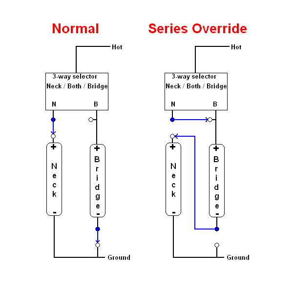 In the Series Override mode, the position of the 3-way selector becomes irrelevant. The Bridge (+) is ultimately connected to hot regardless of the selection of Neck, Both, or Bridge. The Neck (+) is linked in series with the Bridge (-). |
|
cmscss
Meter Reader 1st Class
Ad-free Angel
Posts: 78
Likes: 2
|
Post by cmscss on Dec 16, 2017 14:06:44 GMT -5
Thanks heaps guys, very much appreciated!
So if we keep the original idea of a 3-way and 2 DPDT switches, how do I modify the diagram to accomodate my selector switch?
I don't really understand the different between my selector switch and the one used in the diagram.
Thanks again guys, you guys are awesome.
Cheers
Ben
|
|
cmscss
Meter Reader 1st Class
Ad-free Angel
Posts: 78
Likes: 2
|
Post by cmscss on Dec 16, 2017 14:07:21 GMT -5
Aghhhh, sorry, forgot top refresh before posting. Reading your new posts now.
|
|
cmscss
Meter Reader 1st Class
Ad-free Angel
Posts: 78
Likes: 2
|
Post by cmscss on Dec 16, 2017 14:10:41 GMT -5
OK let's keep the original idea of a 3-way selector and 2 DPDT switches.
How do I modify the diagram to accomodate my selector switch? Or has that already been answered and I don't understand!
|
|
|
|
Post by reTrEaD on Dec 16, 2017 14:31:09 GMT -5
OK let's keep the original idea of a 3-way selector and 2 DPDT switches. Okay. So the plan is 3-way DPDT Series Override DPDT Phase switch for Neck pickup. How do I modify the diagram to accomodate my selector switch? Or has that already been answered and I don't understand! Not fully answered. My most recent drawing suggests the overall strategy minus the phase switch. But we haven't connected all the dots yet. I'll post a drawing later using your original diagram and erasing all the connections. The first part will be to show the connections to hot and where the N and B from the selector block in my drawing end up in the selector you're using. Might be later today. |
|
cmscss
Meter Reader 1st Class
Ad-free Angel
Posts: 78
Likes: 2
|
Post by cmscss on Dec 16, 2017 15:12:32 GMT -5
|
|
|
|
Post by reTrEaD on Dec 16, 2017 16:49:06 GMT -5
Thanks for posting that blank, Ben. I had already been chopping up the original but I saved that blank to my computer. Might need it later. Here's repeat posting of the general overview and a partially completed diagram. 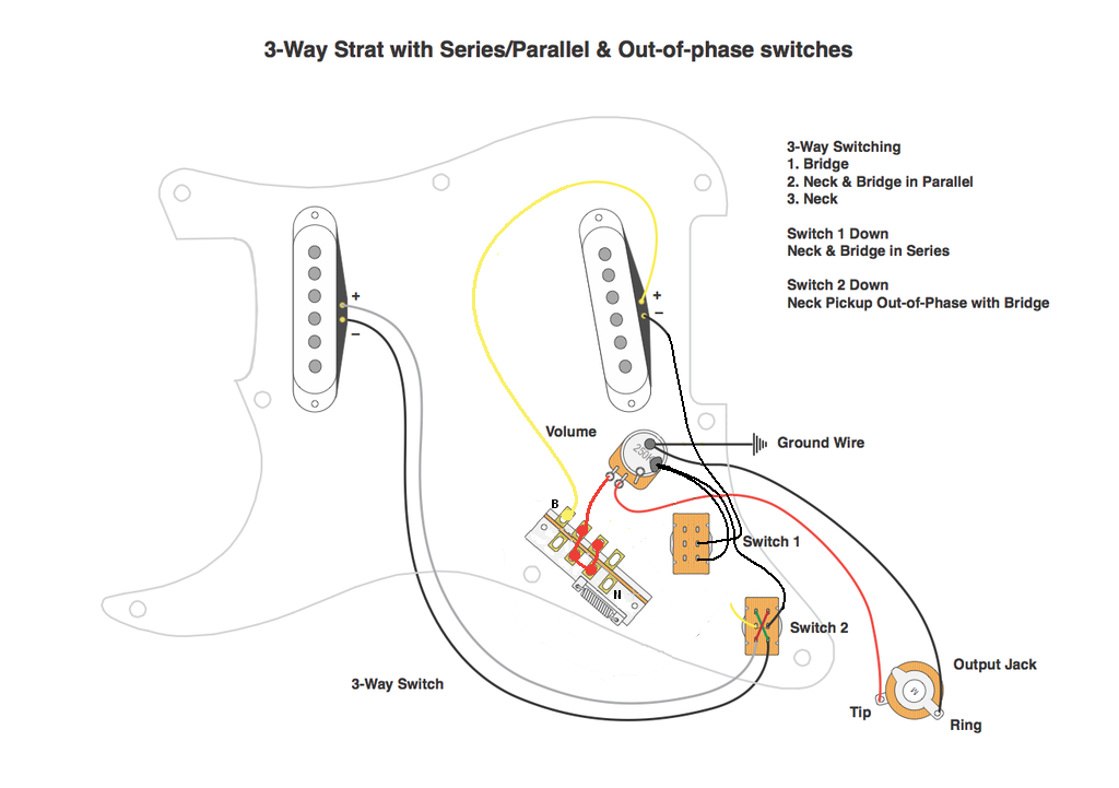 The 3-way has been configured in the method Fender usually employs on the Telecaster. One pole is for B the other for N. The lugs necessary to connect those poles to hot in the various positions have been joined together and connected to the CW lug of the volume control (hot). I drew the connection for the Bridge (+) to the 3-way. The Bridge (-) is connected to one pole of Switch-1. When the switch is in the up position, a connection is made to ground (as drawn). Also drawn is ground connection between the Neck phase switch (Switch 2) and ground. If you like, you can make the rest of the connections. If necessary, I can talk you through it in steps. For instance, the N pole of the 3-way needs to connect to the pole (middle lug) on the left side of Switch-1. Would you like to try? Have I given you enough information or should I just complete the drawing? |
|
cmscss
Meter Reader 1st Class
Ad-free Angel
Posts: 78
Likes: 2
|
Post by cmscss on Dec 16, 2017 17:38:34 GMT -5
Thanks heaps for this. Once I'm back from work I'll have a good look and see if I can work it out. Cheers
|
|
cmscss
Meter Reader 1st Class
Ad-free Angel
Posts: 78
Likes: 2
|
Post by cmscss on Dec 17, 2017 19:27:28 GMT -5
|
|
|
|
Post by reTrEaD on Dec 17, 2017 23:06:29 GMT -5
I'm glad you made an attempt but that one won't work. Wait for one of the other Nutz to proofread this to insure I haven't made an error but I'm pretty sure this will get you where you want to go. EDIT: DO NOT USE. DOES NOT WORK. |
|
|
|
Post by sumgai on Dec 18, 2017 2:42:23 GMT -5
reTrEaD,
The N+ never gets to the output while S1 is in parallel.
The series override will be heard in Pos 1 and 2, but not in Pos 3.
You have jumpers between the two poles that are superflous.
Did the blue wire perhaps "fall short" of the proper terminal that would make everything work as intended?
And if it were me, I'd modify the diagram text for S1 to reflect the override funtionality.
sumgai
|
|
|
|
Post by newey on Dec 18, 2017 7:07:35 GMT -5
Yes, sg has it right, attaching the blue wire to the "N" terminal solves the issues.
Note to cmscss: The terminals that RT has labeled as "B" and "N" are more usually called the "Common" or "C" terminals, or sometimes "P" for "Pole". On some switches, it's easy to tell the commons, as they are set a bit further apart from the other lugs. On other types, it can be tricky to tell. Double check your particular switch before you start soldering things.
|
|
|
|
Post by reTrEaD on Dec 18, 2017 10:02:24 GMT -5
Thanks, Team. Yes indeed the blue wire was connected to the wrong lug on the 3-way. I had drawn it to the lug where the pole is on other 3-ways that I'm accustomed to using rather than where the pole actually is on Ben's switch. I had marked that lug with an N in the intermediate drawing but drew to the wrong lug anyway. I guess old habits die hard!  Ben did continuity checks of his 3-way and posted an image on the first page so this should match up correctly. |
|
|
|
Post by sumgai on Dec 18, 2017 11:45:08 GMT -5
Yes, reTrEaD's most recent diagram will do the job.
Ben, this is quite a bit more simple than what you had originally planned. It should sound good, and be easy to use. Good luck!
sumgai
|
|
cmscss
Meter Reader 1st Class
Ad-free Angel
Posts: 78
Likes: 2
|
Post by cmscss on Dec 18, 2017 14:55:27 GMT -5
Awesome guys, much appreciated. Will put this together in the coming days and report back.
Cheers
|
|