|
|
Post by rogergalvaniii on Feb 3, 2018 9:41:33 GMT -5
I have 3 humbuckers. Tone and volume 500k push pull pots. 5 way super switch. Is there a wiring diagram similar to John Hewitt's Super 15 schematic that i can use?
|
|
|
|
Post by reTrEaD on Feb 3, 2018 23:36:36 GMT -5
Is there a wiring diagram similar to John Hewitt's Super 15 schematic that i can use? JohnH has some very good designs and clean drawings. If it's possible to use one of his designs as a starting point, that would probably be a good plan. But a search for "Super 15" came up empty. Can you post a link to the thread to which you're referring? |
|
|
|
Post by JohnH on Feb 4, 2018 2:15:37 GMT -5
ill look for that scheme. Im pretty sure i can find the dagram
|
|
|
|
Post by JohnH on Feb 4, 2018 3:27:08 GMT -5
Here is one: 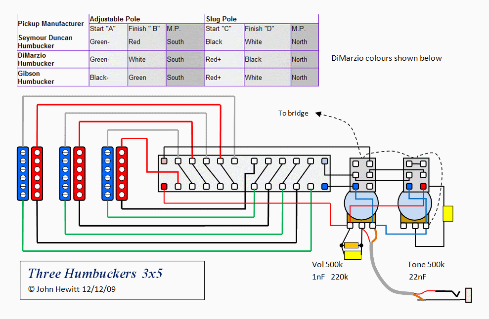 This one is a development/variation 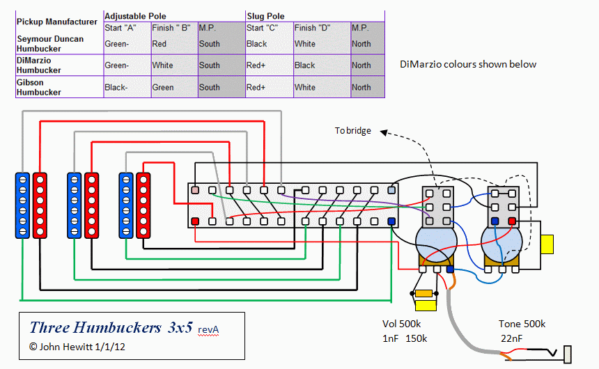 If I remember right, the first one selects adjacent pairs of north and south coils as a 'moving humbucker', from bridge to neck, then offers series or single coil options with those. Need to find its thread... But is that the sort of thing? |
|
|
|
Post by JohnH on Feb 4, 2018 4:14:12 GMT -5
|
|
|
|
Post by rogergalvaniii on Feb 17, 2018 11:06:00 GMT -5
I will try these out.. John Hewitt you are the master!! I'm honored. Thank you Sir!!
I love the super 15.. Could you add to the empty 4th settings ( with both pots pulled up). 5 combinations of 3 pickups in use. An idea for a super 20.
|
|
|
|
Post by JohnH on Feb 17, 2018 16:11:43 GMT -5
Thanks for your comments. THe Super15 was an HSH (rather than HHH) design, like this: 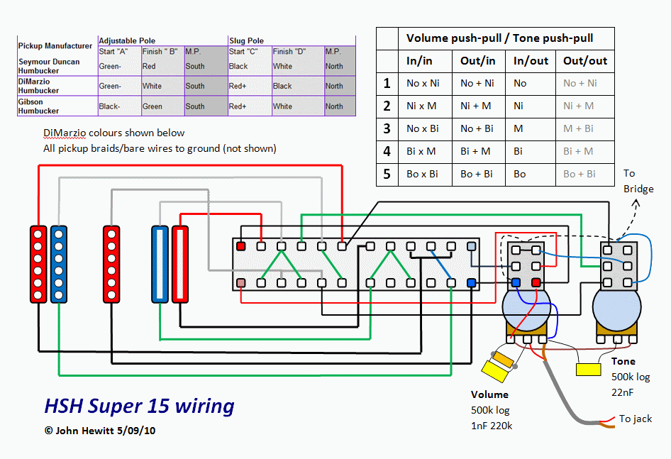 (note on the above, drop the 220k treble bleed resistor down to 150k for best results) Some of the thinking was similar to the HHH ones above. You could have the Super15 in HHH, and the M pickup is just always a full Hb. Need to be careful with wire colours and polarities etc specific to your pickups. |
|
|
|
Post by rogergalvaniii on Feb 27, 2018 1:55:18 GMT -5
Mr. Hewitt.. You are the best there is!!!
Thank you very much.. I'm truly a fan of your skill. I use your super 15 on all of my guitars.
Thanks again!!
|
|
rhaegal
Rookie Solder Flinger

Posts: 1
Likes: 0
|
Post by rhaegal on Apr 16, 2020 18:21:48 GMT -5
Thanks for your comments. THe Super15 was an HSH (rather than HHH) design, like this:  (note on the above, drop the 220k treble bleed resistor down to 150k for best results) Some of the thinking was similar to the HHH ones above. You could have the Super15 in HHH, and the M pickup is just always a full Hb. Need to be careful with wire colours and polarities etc specific to your pickups. Hello! I'm new to this forum. I'm desperately looking for a diagram similar to this one. However, I need H-S-H 1 vol push/pull for Series/Parallel 1 tone push/pull for coil splitting. I understand I might have to use a superswitch. Hope you can help me and thank you in advance. Regards |
|
|
|
Post by reTrEaD on Apr 16, 2020 18:57:08 GMT -5
Hello! I'm new to this forum. I'm desperately looking for a diagram similar to this one. However, I need H-S-H 1 vol push/pull for Series/Parallel 1 tone push/pull for coil splitting. I understand I might have to use a superswitch. Hope you can help me and thank you in advance. Regards This diagram mentioned by JohnH earlier in this thread might suit your needs. And yes, it does require a superswitch.  |
|
yahont
Rookie Solder Flinger

Posts: 8
Likes: 1
|
Post by yahont on Jun 23, 2020 16:04:45 GMT -5
Greetings to all! I'm new here. Unsuccessfully looking for a wiring option H-H-H, 1vol/push-pull, 1 tone/push-pull, 5-way super switch, but the photo is not reflected (possibly deleted from the server) please send me a complete scheme and various variations if someone has it available! I have SD TB-14 in bridge, SD aph-1b in neck, and China Hot rails mini humbucker in Middle. All pickups are 4-wire conductor. Thank you very much in advance!
|
|
|
|
Post by thetragichero on Jun 23, 2020 21:06:23 GMT -5
yahont welcome! it seems as if the original image hoster doesn't allow hotlinking but they're still viewable by right clicking. I've uploaded them elsewhere  
|
|
yahont
Rookie Solder Flinger

Posts: 8
Likes: 1
|
Post by yahont on Jul 6, 2020 14:49:30 GMT -5
Hi everyone! in what positions of the super switch and push-pulls which coils work in both versions of the circuit (three hum’s 3x5 and three hum’s 3x5 revA)  Like on photo...H-S-H in this thread... |
|
|
|
Post by JohnH on Jul 6, 2020 17:44:36 GMT -5
|
|
|
|
Post by JohnH on Jul 6, 2020 23:12:58 GMT -5
I had another look.
The earlier diagram is the easier one to think about.
Both knobs in and you get moving series humbucker of
Bridge both coils
Bridge x Middle one coil of each
Middle both coils
Middle x Neck one of each
Neck both coils
Pull the tone knob and its as above but now each coil pair is parallel, for a brighter cleaner sound
Or, pull the volume knob instead and you get just one single coil from each pair starting from the bridge end.
That diagram is all fine, just use a 150k instead of 220k in the treble bleed circuit.
Rev A
The second rev A version is more smart-a$$ clever-clever. It was aimed at getting additional options based on coil combinations of a bridge and a neck coil, which is a very nice distinctive extra option. You pull the volume to set this up, and it happens with the 5-way set to bridge and you can have series or parallel NB combos.
Instead of single coils being selected by the volume switch, this now happens by turning the tone pot, only in this setting with volume knob out and if tone is in. If so, then the tone pot acts with single coil at 10, and normal humbucker from 9 down to 0.
|
|
stratobob
Rookie Solder Flinger

Posts: 8
Likes: 1
|
Post by stratobob on Oct 31, 2020 17:45:34 GMT -5
Good evening, I hope everyone is well. I am sending my message from France.
First of all I would like to thank Mr Hewitt for the diagram of the HHH super 15 that I intend to apply on an old Aria Pro 2 that I have refurbished. The problem for me is that I am trying to understand the color code of the pickups manufacturers and to compare them to mine now that I have discovered which is which (positive and negative on each coil) because on your diagram which is really very clear and despite the table of manufacturers I cannot understand where the positives and negatives of each coil are... I don't undertand the table...
This is the diagram of my pickups :
___________
+ Green ----(___________)---- Red -
___________
+ Black ----(___________)---- White -
Thank you for your help I hope I was clear enough it's not easy to find the good words to be understandable, I just need to know which one of my wires is the white one on your diagram, same for the red, green and black.
Be safe, Stratobob.
|
|
|
|
Post by JohnH on Oct 31, 2020 18:10:28 GMT -5
Good evening, I hope everyone is well. I am sending my message from France.
First of all I would like to thank Mr Hewitt for the diagram of the HHH super 15 that I intend to apply on an old Aria Pro 2 that I have refurbished. The problem for me is that I am trying to understand the color code of the pickups manufacturers and to compare them to mine now that I have discovered which is which (positive and negative on each coil) because on your diagram which is really very clear and despite the table of manufacturers I cannot understand where the positives and negatives of each coil are... I don't undertand the table...
This is the diagram of my pickups :
___________
+ Green ----(___________)---- Red -
___________
+ Black ----(___________)---- White -
Thank you for your help I hope I was clear enough it's not easy to find the good words to be understandable, I just need to know which one of my wires is the white one on your diagram, same for the red, green and black.
Be safe, Stratobob. Hi Stratobob, welcome to GN2 Quite a few makers use those same colours, but in different arrangements. From your listing, they could be the same as Seymour Duncan, in which case we know what to do. There are various ways to work it all out. But if they are the existing pickups wired in a simpler circuit that works fine, then the easiest thing is to tell us how they are wired now. 1. Which wire goes to ground? 2. Which wire goes to the main switch? 3. Are there two wires joined (eg red/white), and which are they? 4. Are all pickups wired the same as 1, 2, 3 ? If this doesn't apply to existing wiring, we will move on... |
|
stratobob
Rookie Solder Flinger

Posts: 8
Likes: 1
|
Post by stratobob on Nov 1, 2020 2:46:18 GMT -5
Hi Stratobob, welcome to GN2 Quite a few makers use those same colours, but in different arrangements. From your listing, they could be the same as Seymour Duncan, in which case we know what to do.There are various ways to work it all out. But if they are the existing pickups wired in a simpler circuit that works fine, then the easiest thing is to tell us how they are wired now.1. Which wire goes to ground?2. Which wire goes to the main switch?3. Are there two wires joined (eg red/white), and which are they?4. Are all pickups wired the same as 1, 2, 3 ?If this doesn't apply to existing wiring, we will move on... Good morning Mr Hewitt, thank you for your answer, I am honored. 1. As you can see on the pictures I actuallly have 5 wires on each pickup but I didn't mention the 5th one because it's the ground and I guess it goes on the top of the pot (top on the pot lol) 2. I don't know wich wire goes to the main switch from my pickups, on your diagram they all go so from mine too right? 3. When I received them, the ground wire was joined to the black, the green to the white and the red was just alone. 4. No, all pickups are not the same, neck and middle are Belcat Alnico V Hot Rail Blade Strat Coil Pickup www.amazon.com/-/es/A0985/dp/B00APTW2HK?language=en_US and bridge is FLEOR Alnico 5 Bridge Pickup Double Coil Humbucker www.amazon.com/FLEOR-Electric-Guitar-Humbucker-Pickups/dp/B073D4BGFW/ref=sr_1_3?crid=25CDY2PR04KVP&dchild=1&keywords=fleor+alnico+5+humbucker&qid=1604216281&sprefix=fleor+aln%2Caps%2C227&sr=8-3
on wich red and white are joined, ground and green are joined too and black is alone but I didn't test the polarity yet because I have to go working now but I will tonight.
Thank you very much for your help, I really appréciate. Have a nice day Stratobob   |
|
|
|
Post by newey on Nov 1, 2020 6:18:18 GMT -5
3. When I received them, the ground wire was joined to the black, the green to the white and the red was just alone. This indicates that these pickups share wire colors with Gibson humbuckers, which means you can use the Gibson wiring in the chart above to translate wire colors from JohnH's diagram, which uses DiMarzio colors. However, while it is likely that these are the same as Gibson, we don't know for sure (without some testing on your part) wheether the slug and screw coils are the same as Gibson, they could be the opposite way around- meaning that the diagram would work, but you might not be selecting the appropriate coils, inner versus outer. This would indicate that this pickup shares wire colors with DiMarzio pickups, and so should follow the diagram. But, again, we don't know that the screw/slug coils are the same as in DIMarzio, nor do we know the magnetic polarity of each coil, North or South. Anytime you are using dissimilar pickups, you run the risk that they will be out-of-phase with each other, without first testing them to ascertain the polarity. Here, we have the additional question of whether the screw and slug coils matcvh up with Gibson's and DiMarzio's, respectively. Testing this before wiring is therefore highly recommended, particularly since this scheme is based, as John has said, on the "moving humbucker" idea, so whether the screw coil or slug is selected matters a lot here. And, if the phasing is also wrong when you wire it, that's easily corrected, but it does mean going in again to swap wires on the bridge pickup. Better to know for sure beforehand. Your photos don't help with this issue. To test for which coil is screw vs. slug, you will need a multimeter, and to test for the magnetic polarity, you will need a toy compass, although there are other ways of testing as well. |
|
|
|
Post by JohnH on Nov 1, 2020 14:47:33 GMT -5
newey is totally on the money. We can definitely get this scheme to work but with different pickup makes, particularly when they are not from the big best-known makes, it is pretty much a guess at how they will interact in a scheme such as this unless we step through a testing process. They may well use a known wire colour scheme, and work fine in a standard design and with only one pickup make. But they may not follow the DiMarzio or Gibson intent fully in terms of magnetism and slug/screw orientation etc. The first things to figure out/check, using the multimeter: On each pickup, which are the wires that go to each coil, that is there is a measurable resistance between them of a few k, rather than infinite resistance when measuring between wires from different coils? Work out relative north and south for each pickup coil poles- using the compass is best, or you can just bring one pickup face to face with another and figure it out from attraction or repelling. Need to work out how to place the pickups so you get alternating north and south, like on the diagrams (you can work with nsnsns or snsnsn, its ok) That will give a good start. Then phase tests are needed. See if you have what you need to do any of the approaches on this thread: guitarnuts2.proboards.com/thread/4938/testing-phase-screwdriver-pull-test |
|
stratobob
Rookie Solder Flinger

Posts: 8
Likes: 1
|
Post by stratobob on Dec 3, 2020 7:11:36 GMT -5
Hi, I hope everybody is wel
Sorry to be so long to answer and thank your for your precious help. I did the test on the fleor pickups (Neck and middle) that's what I show on my first message :
___________
+ Green ----(___________)---- Red -
___________
+ Black ----(___________)---- White -
This is the fleor pick up, on the the top the green is positive matching with the red negative and on the bottom the black is positive matching with the white negative... But that said there is no screw and slug on this rails so it makes it more difficult. Now do I really need a compass to make it ?
Thank you, take care!
Stratobob
|
|
yahont
Rookie Solder Flinger

Posts: 8
Likes: 1
|
Post by yahont on Jan 31, 2021 15:43:17 GMT -5
Hello! I am addressing the community with a problem. First I soldered rev.A.
When all two push-pulls are down In the first position of the super switch (bridge humbucker only), the bridge humbucker works. Then pos. 2-3-4-5 there is no sound. If you UP the tone push-pull, then 2-3-4-5 works, but apparently with cutoffs.
That is, the problem is that positions 2-3-4-5 do not work when push-pulls is Down.
Soldered for 1 option, there is no sound at all when push-pulls are Down. Up the tone push-pull - all 1-2-3-4-5 work but with cutoffs.
What could be the mistake?
|
|
yahont
Rookie Solder Flinger

Posts: 8
Likes: 1
|
Post by yahont on Jan 31, 2021 16:06:37 GMT -5
Forgot to clarify, all 3 humbuckers are Seymour Duncan. The green wire on all three is connected to the 5th wire of the humbuckers - a braid.
|
|
|
|
Post by newey on Jan 31, 2021 17:48:45 GMT -5
The green wire on all three is connected to the 5th wire of the humbuckers - a braid. Did you disconnect th green wire from the braided one? You would need to do so to wire this properly. I don't know if that explains your problem or not, but the green wire would need to be separated from the braided one. |
|
yahont
Rookie Solder Flinger

Posts: 8
Likes: 1
|
Post by yahont on Feb 13, 2021 6:42:57 GMT -5
Hello! Yes, i disconnect all the green wires from the braided one, But it’s not resolve my problem...
In first position of superswitch with vol and tone push-pulls down only bridge full Humbucker works. 2-3-4-5 positions not working. If I up the tone push-pull in 1-st pos. works half bridge hum, then 2-3-4-5 works all 3 hums, but in half mode (I think, because sound more quiet than bridge full hum).
|
|
yahont
Rookie Solder Flinger

Posts: 8
Likes: 1
|
Post by yahont on Feb 13, 2021 15:02:10 GMT -5
I fixed it! Sorry friends! for some reason, I thought that the jumpers are part of the superswitch. But looking at version 1 and rev.A I realized that these are the circuit elements that need to be soldered. In general, as I soldered all the jumpers - everything worked! Thank you all for your help! Thanks to the author of the scheme! I supplemented this scheme with a piezo bridge. All the ideas to come to fruition. Everything is cool!
|
|
stratobob
Rookie Solder Flinger

Posts: 8
Likes: 1
|
Post by stratobob on Feb 14, 2021 12:15:49 GMT -5
Hi!! Soldering in progress... 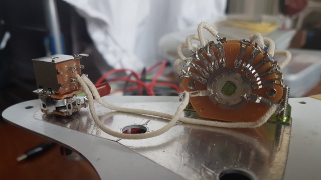 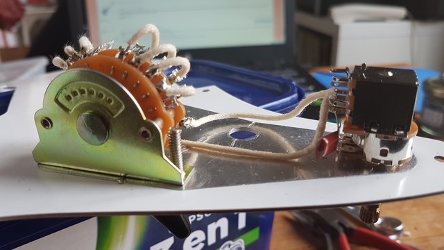 |
|
stratobob
Rookie Solder Flinger

Posts: 8
Likes: 1
|
Post by stratobob on Feb 24, 2021 16:10:02 GMT -5
Good evening, After watching thousands of videos I finally found out what is north, south, start and finish and I finally understood how my pickups are set. Anyway I wanted to thank you for your help, it's not always easy to be understood when you don't speak the same language and I try do it by myself without Google translate. I soldered the pickups temporarily just to check that everything work and yes it works... Ok it's not the sexiest wiring that you have seen in your life but hey, it's my first time so I'm pretty proud of me and anyway I have to remove it all for painting the body. Actually putting the pots face to face was probably not the best idea for soldering. Thank you again for your support and patience... Stratobob 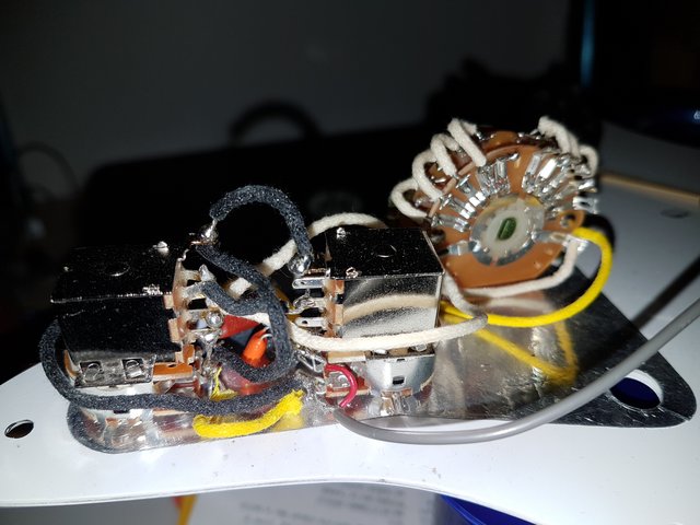  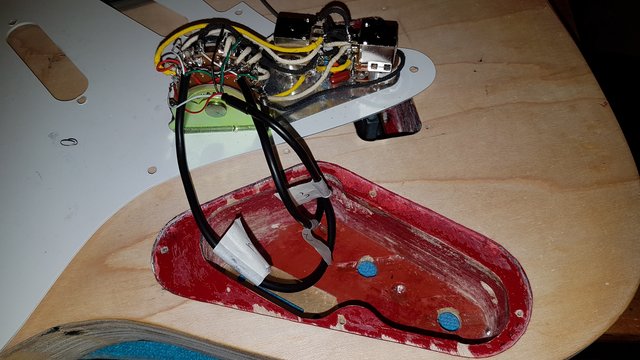 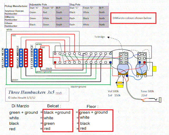 |
|
|
|
Post by newey on Feb 24, 2021 16:26:27 GMT -5
Glad you got it working, stratobob! Once you get the painitng done, please post some pictures of the end result in the Gallery, and maybe post some soundclips for us (if you are set up for recording and ambitious enough to do so!)
|
|
|
|
Post by frets on Feb 24, 2021 16:46:01 GMT -5
Hey Stratobob,😸😸
I think your wiring looks fantastic. Congrats!! Can’t wait to see the guitar.
|
|