|
|
Post by ourclarioncall on Nov 19, 2019 19:01:58 GMT -5
Hi all, newbie with a question regarding controlling volume on a guitar like a strat
Would it be possible to somehow have adjustable volume on a 5 way switch instead of a volume pot ?
For example the 5 way switch at the bridge position could be the lowest volume , then it incrementally increases to full volume as you get the neck position on the 5 way
I guess there might be a way you could do it by having 5 volume pots set to different volumes hidden in the cavity under the pickguard that is wired to a 5 way switch ?
Cheers
|
|
|
|
Post by JohnH on Nov 19, 2019 20:26:22 GMT -5
Hi ourclarioncall and welcome to GN2
Could certainly do that, using a series of fixed resistors worked out to give 5 evenly-spaced steps.
Short of having some bright idea, that escapes me right now, I'd say a normal 5-way would not be ideal, since the 2 and 4 positions are shorted, not independent. A switch with five independent settings would be best. Could be a rotary, or a half superswitch.
|
|
|
|
Post by ourclarioncall on Nov 19, 2019 21:07:20 GMT -5
Could be a rotary, or a half superswitch. Thanks JohnH ! What is a half superswitch ? Is that half of a superswitch ? Or something different than a superswitch ? I’m sure I have a superswitch in my tool box I bought years ago to do the mike Richardson mod Thanks |
|
|
|
Post by reTrEaD on Nov 19, 2019 21:44:31 GMT -5
|
|
|
|
Post by ourclarioncall on Nov 20, 2019 10:18:23 GMT -5
Ah, thanks !
Now I’ve learned something new. I have a double wafer , but didn’t realise you got single wafer versions
|
|
|
|
Post by ourclarioncall on Nov 20, 2019 10:39:21 GMT -5
The thought I had was to have three 5 way switchs
Well, actually if I have two single coil pickups , then I would have 5, 5 ways switches in total. A volume and tone for each pickup and then a pickup selector for both pickups.
Selection would be
1. Kill switch
2. Bridge
3. Bridge and Neck in parallel
4. Bridge and Neck in series
5. Neck
The idea would be for testing different tone combinations and the pickups would be sliding/moveable.
One for volume, one for tone (with various different caps??) and one for pickup selection
———
I’m wondering if on the volume 5 way I could have one of the positions where there is no resistance at all, as if it was hard wired to the input jack with no volume pot in the circuit . Hope I’m making sense . Possibly like a “no load” pot ? And then the other four positions on the 5 way could give incremental increases in volume
And the same with the tone 5 way switch , where one of the selections is like having no tone pot at all, then the other four have varying caps ?? connected.
And maybe for the pickup selector , have one of the positions as a kill switch and the other 4 as pickup selections.
—-
By the way, I’m just thinking out loud and it’s just nan idea to kick around , I’m not anywhere near the stage of actually building anything , so no pressure to come up with solid soloution just yet
Cheers !
|
|
|
|
Post by reTrEaD on Nov 20, 2019 11:18:17 GMT -5
Hi ourclarioncallAll the things you're targeting could be done, although I'm not sure about whether you'll actually find using lever switches for volume and tone controls to be worth the effort. In each position of the volume controls, you'll be able to have whatever division ratio you desire or a connection that's similar to a no-load with the pickup being directly connected with no resistor in parallel with the pickup. In each position of the tone controls, you'll be able to have any combination of capacitor and resistor you want. The master selections present no problem, other than the #3 position. (Bridge and Neck in parallel). If your minimum volume on either of the volume controls is zero (a shunt), this will work just fine when the two pickups are selected in series, but will be a problem when two pickups are selected in parallel. The shunt created when one volume is at zero, will kill all sound from the other pickup, regardless of the setting of the volume setting on the other pickup. I think this might be avoided by some clever use of the additional unused poles on the two volume switches and the master selector. |
|
|
|
Post by ourclarioncall on Nov 20, 2019 16:01:18 GMT -5
Hi ourclarioncall All the things you're targeting could be done, although I'm not sure about whether you'll actually find using lever switches for volume and tone controls to be worth the effort. Your maybe right. What I would maybe find more useful for volume might be having 3 volume options. Maybe on a three way vintage strat selector switch.. The centre notch would be normal room volume , then either side would be set to cut the volume in half and the last setting to boost the volume by 10db or whatever would work for a guitar solo . But most of the time it would be set on the centre “full volume “ setting . The half volume might be good for when having two pickups on and letting one be more dominant in the mix. Or I suppose just simply the half volume might just come in handy to be a bit quieter. I teach guitar for a living so half volume could be handy when I’m playing along with my students or when I’m playing and talking at the same time. The volume boost setting could be handy when in a band context when fighting with the sound man I could also just settle for some sort of simple two throw switch with normal volume and half volume Same with the tone, I could maybe settle for a double throw switch with normal tone and then a darker half tone setting This Would fix the bridge and Neck in parallel #3 setting as there is now no shunt ? Cheers |
|
|
|
Post by JohnH on Nov 20, 2019 16:30:31 GMT -5
It's clear that you know how you use your gear and know what you want. For myself, I would have difficulty chosing a very limited range of settings, since needs for volume very. That being said, I normally control at the amp rather than the guitar. But if the guitar was to be the main control position, have you thought of retaining the pots, and having a switch to bypass them? so you'd have either whatever the pot was set to, or full volume? Or maybe full volume, one controlled by a pot, and one fixed reduced volume? (Same idea for tone)
|
|
|
|
Post by ourclarioncall on Nov 20, 2019 16:40:12 GMT -5
It's clear that you know how you use your gear and know what you want. For myself, I would have difficulty chosing a very limited range of settings, since needs for volume very. That being said, I normally control at the amp rather than the guitar. But if the guitar was to be the main control position, have you thought of retaining the pots, and having a switch to bypass them? so you'd have either whatever the pot was set to, or full volume? Or maybe full volume, one controlled by a pot, and one fixed reduced volume? (Same idea for tone) My problem is I’m a minimalist at heart , yet very creative and want to explore every wiring scheme possible haha, so I can figure out the handful of best sounds , then go back getting rid of everything except what I need to get those few sounds. I do like having the volume pot for dialling in just what I need when I need it but thought a 5 way with 5 volume choices would be enough to keep me happy and also a quicker way to dial in the amount of volume I want . Also shallow things like asthetics n stuff come into it too. I like switch’s and think they are cooler than pots 🙂 Also pots are bulky (minimalist thing again) |
|
|
|
Post by ashcatlt on Nov 20, 2019 17:45:40 GMT -5
I have stepped V and T in my Rickenbacker. I used rotaries, but it's not different from a proper 5 way switch. Had pics of that up here a while back, but I'm sure they are long lost. They can both be done with just one pole as long as you're not also trying to also switch caps or something OR want a No-Load position for the Volume. You basically just wire your resistors between the adjacent lugs and end up with the same 3 terminals you'd have on a pot. For the V you use all three, and for T only the two. Edit - Here's a good schematic of what I'm on about, but with 6 steps. It's kind of up to you to figure out the best actual resistor values. I figured it to be more or less equal steps on the logarithmic scale, but I'm not sure it was the best choice. 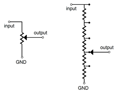 |
|
|
|
Post by ourclarioncall on Nov 20, 2019 18:21:51 GMT -5
Ashcatlt
Cool, how does it work for you in real life ?
Why did you chose the rotaries instead of pots?
Cheers
If you were to do it all again would you change anything ?
|
|
|
|
Post by ashcatlt on Nov 20, 2019 21:35:19 GMT -5
Cool, how does it work for you in real life ? Honestly, I almost never use the individual V and T controls, and not just because they are kind of loose and if I try to turn them the whole thing just spins and I haven't bothered to open it up and tighten them down. :/ Because I'm a whackjob and just generally don't use the pots anyway. IIRC, my Vs use 2 poles in order to allow a No Load option and I think also allow it to turn one pickup off in series mode without killing the whole thing, but it's been a while, so I'm not super sure about exactly what I did in there.  |
|
|
|
Post by ourclarioncall on Jan 18, 2020 19:57:16 GMT -5
This was my very first post on GN2 and I’m just coming back to this again to figure out how to apply some of these ideas In a circuit
I would like to use a simple hypothetical example to get a bit of understanding
So let’s say I have one single coil and it’s wired straight to the output jack. But I want a simple way to lower the volume of the pickup , lets just say I want roughly half volume , and it must via a toggle switch.
From what’s been said already it sounds simple enough. I am thinking I could do this with a DPDT toggle switch and a resistor ?
If that’s correct , I don’t know if the resistor is wired in series with either the hot or ground wire or if it’s wired in parallel with both hot and ground ?
|
|
|
|
Post by sumgai on Jan 19, 2020 0:58:59 GMT -5
(In the voice of Robby the Robot from Lost In Space:) Danger, OCC, DANGER!! Big words ahead!!
Simply stated, you don't need a DPDT switch for this, an SPST will do, but in point of fact, you won't achieve the results you intend.
While I sometimes assail ashcatlt for his insistance that the world is a voltage divider, in this case he is absolutely correct. In the shortest sentences possible, a Volume control is wired in parallel with the pickup, and a varying amount of the resultant decrease (thanks to the wiper) is in parallel with the amp's input (via the output jack and cable, of course.)
But that's too simple by half. What's really happening here (and again, this is the simple version), is that each side of the Vol control is "loading" the other components. That load is usually stated as an "impedance" value. In DC terms, we call it resistance, but in a guitar, we speak of AC frequencies, so it's correctly called impedance.
Now, to the heart of the matter. Resistors have no frequency dependancies, they are frequency-neutral. But they do present a load to any other component, and the size of that load (and its effects on the other component(s)) depends greatly on how it's connected. You did, rather wisely, ask about series or parallel, and that's where the rubber meets the road.
In essence, if you insert a single resistor in series with a pickup, and on out to the amplifier, then you are changing the load only a tiny amount... if at all noticible. The value of the resistor will vary greatly, depending on how "hot" the pup is, and whatever the input impedance of the amp might be. Remember, the amp expects to see a certain value impedance coming in. Mess with that too much, and things start to go bump in the night.
Additionally, a pickup expects to see, and it works best into, a certain valued load. This is almost universally a Volume control, with a Tone control added in for good measure. Neither of them are absolutely necessary for the pup to work (witness a Blower switch, etc.), but they do have an effect on the signal that we generally call acceptable.
So, that simple series resistor? Doesn't do much. If you make it large enough, then sure, you'll get a reduced volume. But what about the tone?  That's gonna require either some Engineering-level analysis, or a large box of resistors that can be inserted into the circuit, with multiple test runs very time you make a change. Oof. (And not oof-da.) That's gonna require either some Engineering-level analysis, or a large box of resistors that can be inserted into the circuit, with multiple test runs very time you make a change. Oof. (And not oof-da.)
ash's multiple resistor chain is a direct substitution for the Vol control, terminal for terminal. Instead of the wiper being infinitely variable, it's cast in concrete - one of the 5 steps, and that's it, baby. But here's the culmination of all I've said so far - that resistance chain is presenting the exact same load to the pickup at all times, and it's varying the load out to the amp, just as a normal Vol pot does. The amp is made to handle that variance, so no sweat on that account.
Bottom line for you? You'll want two resistors, at the least. Wire them in series with each other, then that combo is wired in parallel with the pickup. Your switch can then select the top of that series-resistor-pair (max signal level to the amp, just like having the Vol pot all the way up) or it selects the terminal between the pair, effectively forcing the signal to come out at a reduced level. Capish? See ash's diagrams again, and imagine the chain with only two resistors, that should make things easier to envision.
Remember, nearly everything you can think of, and a lot more besides, affect one's tone. This business of impedance is but one not-too-small factor. Good luck!
HTH
sumgai
|
|
|
|
Post by ourclarioncall on Jan 19, 2020 18:47:48 GMT -5
sumgaiHi. I was actually having a look at volume pots again. well, I’m not sure if I’m getting it but here’s a few attempts . No doubt it will reveal my comprehension or lack of ! Attempt 1  Attempt 2  Attempt 3 
|
|
|
|
Post by sumgai on Jan 19, 2020 22:50:53 GMT -5
occ, Errr, nope, none of the above. Observe:  When the SPST switch is closed, the signal's full volume will pass to the pedal(s), amp, what have you. When the switch is open, then a reduced signal level will be passed outward. Note at this point in the conversation that we are changing the total resistance value (by shorting one of the resistors), and thus we are also changing the overall impedance. Most pickups will work well with the kind of change, and I can't think of any amplifier that would be bothered, either. However, some pedals might come unsoldered at the seams, should an impedance change of this magnitude be presented to their input jack. Just an FYI. HTH sumgai |
|
|
|
Post by ourclarioncall on Jan 19, 2020 23:34:30 GMT -5
sumgai ah, I misread SPST the first time you wrote, I thought it was SPDT. I’m sure these schematics are simple enough to understand but I’m really struggling to see what this would look like on the SPST I think if I could see what it looks like then I think after re-reading you last posts a couple times it would all click in my brain
|
|
|
|
Post by reTrEaD on Jan 20, 2020 0:47:56 GMT -5
occ, Errr, nope, none of the above. Observe: When the SPST switch is closed, the signal's full volume will pass to the pedal(s), amp, what have you. When the switch is open, then a reduced signal level will be passed outward. Note at this point in the conversation that we are changing the total resistance value (by shorting one of the resistors), and thus we are also changing the overall impedance. Most pickups will work well with the kind of change, and I can't think of any amplifier that would be bothered, either. However, some pedals might come unsoldered at the seams, should an impedance change of this magnitude be presented to their input jack. Just an FYI. HTH sumgai Well, ackshally ... For half volume (-10dB) the value of the bottom resistor to the total resistance is roughly 31.6%. So if we look to emulate a 250k pot with the correct volume reduction, that gives us about 78k. That seems like a significant tone-suck to me, when the volume is at max. I think I'd spend a couple of extra pennies for a SPDT switch. Using standard values for resistors, the bottom would be 82k and the top would be 180k giving us a total of 260k. And maybe JohnH could run a ToneFreak sim to determine the optimum value of the capacitor for this unique application.  |
|
|
|
Post by sumgai on Jan 20, 2020 13:17:04 GMT -5
reTrEaD,
You will be glad to note that I did not specify any values for those resistors. That was on purpose, as any discussion of perceived volume level differences is necessarily fraught with "loose" definitions of things like Sound Pressure Level, intensity, loudness, exposure time, spectral composition, temporal structure, information content and subjective mental attitude. Whew!
But roughly, you've correctly spelled out the electrical side of how to cut a speaker's perceivable output in half, if we don't get into exacting definitions. And the idea of adding the cap is a great next step. I was going to go down the road of more complex switching to avoid mis-loading the pup, but your capacitor idea might obviate the higher level switching schema I was envisioning. Or as an alternative, I might have simply upped the resistor chain's total value in the first place, allowing the lower leg to present a greater value (or, lesser chance of Tone Suck) to the pickup. (For the record, I have always been a proponent of 1Meg pots - you can always reduce treble frequencies with various controls, but if they've been effectively removed by a too-low value Volume pot, they can never be recovered.)
BTW, if I didn't know better, I'd swear that you had access to my AutoCAD drawing(s) - that addition caused me to do a double-take!
sumgai
|
|
|
|
Post by ourclarioncall on Jan 20, 2020 14:46:36 GMT -5
Full disclosure
I am hoping to integrate these volume switches at some point into my circuit over on the other thread (2 pickup Brian May with half out of phase ?) which I Could call “The Tenacious Tartan Toggler” or “The stubbornly strict switch” 😉
So before you guys go and do lots of mental gymnastics , will that cause difficulties because of the complexity of series/parallel etc like the capacitors did?
Just so I don’t waste your time
However I would still be very interested to see how this would work and what it looks like wired up for a simple one pickup to the output jack circuit
|
|
|
|
Post by ashcatlt on Jan 20, 2020 20:08:50 GMT -5
sumgai’s is wrong and he told you why. It shorts the top resistor rather than switching the output between the top and the middle.
reTrEaD’s is correct with a treble bleed cap. You could snip (NOT short) that cap and have a straight volume switch without the treble bleed.
How any of that fits into the BM thing I can’t say right now and don’t have time to really look atm.
|
|
|
|
Post by sumgai on Jan 25, 2020 16:58:25 GMT -5
sumgai’s is wrong and he told you why. That's quite a feat, being wrong and admitting it in the same breath. Fortunately, that's not quite the full skinny.
As it happens, the topic opened with a sketchy sketch of a DPDT arrangement that would not have done the desired job. After a several other responses, most of them developing the idea into something workable, I inserted the supposition that the job could be done with an SPST. Granted, there were and are drawbacks, but the best place to start designing a resolution to a task is at the most simple level possible.... and then work to improve it.
I provided that simple-as-hell jumping off point, that can't be denied. But rather than go into anything more here, let me just link to reTrEaD's expanded (and excellent) discussion, here:
Volume Switches - mini-toggle, two or three position.
A good rallying point for those who wish to keep control options to a minimum.
HTH
sumgai
|
|
|
|
Post by ourclarioncall on Jan 25, 2020 18:16:40 GMT -5
|
|
|
|
Post by sumgai on Jan 25, 2020 22:30:27 GMT -5
occ,
Errr, the above two images aren't coming through for me. I'll wait until you've posted correct links........
sumgai
|
|
|
|
Post by newey on Jan 25, 2020 23:28:46 GMT -5
OCC-
Your diagram looks good, as per RT's SPDT version.
|
|
|
|
Post by ourclarioncall on Jan 26, 2020 0:33:20 GMT -5
|
|
|
|
Post by ourclarioncall on Jan 26, 2020 0:34:10 GMT -5
|
|
|
|
Post by ourclarioncall on Jan 26, 2020 0:55:10 GMT -5
So, is this like a direct replacement for the volume control ? Hence there is 2 hot wires and 1 ground?
For example one of the hot wires would be going to the 5 way switch in a common Strat wiring
if what i have drawn is correct then it was hard for my brain to accept one leg of the resistor is hanging off the edge of the cliff. Would you just solder a ground wire to this leg? Looks like it might be a bit unstable. If you had a DPDT switch instead could you attach that cliff dangling leg to a terminal on the extra pole (for stability ) ?
also, if I have the diagram correct , then what would it look like if I was just using one single coil to the switch to the output jack ? No 5 ways , no pots etc.
im thinking the hot that would have went to the 5 way could be substituted for the hot wire of the pickup and the ground wire of the pickup..... I’m not sure. It could straight to the output jack but it feels like it should be going through the switch 🤔
|
|
|
|
Post by ourclarioncall on Jan 26, 2020 0:58:21 GMT -5
Ye or Nae ?  |
|


 That's gonna require either some Engineering-level analysis, or a large box of resistors that can be inserted into the circuit, with multiple test runs very time you make a change. Oof. (And not oof-da.)

