|
|
Post by Yogi B on Jun 17, 2020 18:49:17 GMT -5
Putting this side topic into its own thread: (I don't know what advantage is gained by having the terminals laid out in a way that doesn't follow that of a typical import switch.) The Japanese import strat 5-ways have three 'rings' of stationary contacts. They use just two moveable contacts that bridge between these rings and bridge between all three rings in the positions where there are three contacts being made. I haven't dissected one of these, but I think the moveable contacts are of 'bent metal spring' design. Megaswitches use just two rings and four moveable contacts. The moveable contacts are each a polished cylindrical 'rod' laying across the rings. They use tiny coil springs in the plastic rotator to push the rods against the rings. This is a highly reliable design and isn't prone to issues like difference in level of the two rings but I think that would become a problem if there were three rings. Also, they can use exactly the same rotator, coil springs and contact rods in every Megaswitch, regardless of type. All's well up to this point. Why? I don't follow the logic you've used to paint yourself into this corner. You don't need a two-layer board though, you just need to layout the contact pads in a more intelligent way. Borrowing from my Guide to Eyb/Schaller Megaswitches, the truth table for the (original) megaswitch S is this: | Throws |
|---|
| Commons | 1 | 2 | 3 | 4 | 5 |
|---|
Terminal 4
(Common 1) | | Terminal 1
(Middle 1) | Terminal 1
(Middle 1) | Terminal 1
(Middle 1) | | Terminal 3
(Bridge 1) | Terminal 3
(Bridge 1) | | Terminal 2
(Neck 1) | Terminal 2
(Neck 1) | Terminal 8
(Common 2) | | Terminal 5
(Middle 2) | Terminal 5
(Middle 2) | Terminal 5
(Middle 2) | | Terminal 7
(Bridge 2) | Terminal 7
(Bridge 2) | | Terminal 6
(Neck 2) | Terminal 6
(Neck 2) |
Now what they could've/should've done instead is this: | Throws |
|---|
| Commons | 1 | 2 | 3 | 4 | 5 |
|---|
| Common 1 | Bridge 1 | Bridge 1 | Middle 1 | Middle 1 | | | Middle 1 | Middle 1 | Neck 1 | Neck 1 | | Common 2 | Bridge 2 | Bridge 2 | Middle 2 | Middle 2 | | | Middle 2 | Middle 2 | Neck 2 | Neck 2 |
Yes, I know I've got two connections to each of the middle terminals in position 3, I've done that to show that it can be done more than anything. However, doubling-up the pads means that if you wanted a little more clearance between the middle and outer pads that could be done without reliability suffering. And just to prove that the above result isn't an artefact of abstraction, here's what the above table could look like when implemented on a PCB: 
I could have done with this message a few weeks ago, when I pulled an Eyb megaswitch apart. A discrepancy I note to your description is the contacts: it didn't have what I would describe as "cylindrical rods" but rather saddle shaped contacts, which sit over the tops if the springs and fit into slots either side. I imagine this difference made it much easier for me to reassemble mine than when you reassembled yours, though I did still require the help of tweezers. |
|
|
|
Post by frets on Jun 17, 2020 19:57:51 GMT -5
Although tangential, I thought you may be interested in knowing this as FYI in relation to EYB Megas. I asked EYB to make this for me and they did so.  |
|
|
|
Post by reTrEaD on Jun 17, 2020 20:53:39 GMT -5
Putting this side topic into its own thread: Good call. This can be an interesting and productive discussion without derailing an existing thread asking for assistance. I could have done with this message a few weeks ago, when I pulled an Eyb megaswitch apart. A discrepancy I note to your description is the contacts: it didn't have what I would describe as "cylindrical rods" but rather saddle shaped contacts, which sit over the tops if the springs and fit into slots either side. I imagine this difference made it much easier for me to reassemble mine than when you reassembled yours, though I did still require the help of tweezers. I tend to think now that I may have misremembered the innards. It was roughly 15 years ago when I did my disassembly. And just to prove that the above result isn't an artefact of abstraction, here's what the above table could look like when implemented on a PCB:
While that might be possible, this looks as if you're using substantially less rotation between positions than would exist on a 5-position megaswitch lever/detent mechanism. Also I suspect they use a universal plastic rotator for all the non-custom-order megaswitches. There are four possible clockings of the rotator on the square shaft but they all result in the same relationship of the saddles to the foil, since there are four saddles which are 90 degrees apart. Also the 'center' position of the saddles are dead on the x and y axes. That not to say they couldn't use a different plastic rotator for the S & T switch, but I can see why they might be hesitant to do so. I don't have an image of the foil pattern side of an S & T board but I did process this image of the backside to add more contrast.  res.cloudinary.com/gnuts2/image/upload/v1592443685/Switches/mega-grey2.jpg res.cloudinary.com/gnuts2/image/upload/v1592443685/Switches/mega-grey2.jpg |
|
|
|
Post by Yogi B on Jun 17, 2020 22:57:56 GMT -5
Although tangential, I thought you may be interested in knowing this as FYI in relation to EYB Megas. I asked EYB to make this for me and they did so. I already know of those, though I think it is the first time I've seen one with the "3.0"/through-hole style board. I've mentioned them before as a potential solution when a regular super/megaswitch just doesn't have enough poles to cut it for a particular wiring scheme. I even planned to use one in a scheme I designed for myself, but chickened out of it in the end. However, that idea hasn't totally died: my new plan only requires a 6P5T switch as a minimum which I reckon I can just about DIY from a couple of Oak-Grigsby style switches, but a ready-made 8P5T would make things easier and allow me to neaten up the wiring. So, if you don't mind me asking: what does Eyb charge for the thing?
While that might be possible, this looks as if you're using substantially less rotation between positions than would exist on a 5-position megaswitch lever/detent mechanism. Maybe a little less but, I think it's pretty close. Measuring angle between the extents of the pads on the image of the Schaller switch I got roughly 70 degrees, so the angles between mine are 70/5 = 14 degrees, but now I've been challenged on it 15 degrees does seem like a more likely number. Yeah, mines on a 45 degree wonk isn't it (either clockwise or counterclockwise). 
I did it the way I did to make it easier to draw due to symmetry, but that angle could potentially be changed. |
|
|
|
Post by newey on Jun 18, 2020 5:55:57 GMT -5
I had thought the double-wafer 8-pole versions were available directly from Schaller as well, but one had to call and ask, not a regular catalog item IIRC.
I still haven't figured out a use for the Oak/Grigsby 6-way lever I bought a while back, with its wonky switch logic.
|
|
|
|
Post by reTrEaD on Jun 18, 2020 11:16:33 GMT -5
While that might be possible, this looks as if you're using substantially less rotation between positions than would exist on a 5-position megaswitch lever/detent mechanism. Maybe a little less but, I think it's pretty close. Measuring angle between the extents of the pads on the image of the Schaller switch I got roughly 70 degrees, so the angles between mine are 70/5 = 14 degrees, but now I've been challenged on it 15 degrees does seem like a more likely number. Agreed. I think each 'slice' is 15 degrees. A slice that holds a single contact is comprised of a foil section and two half-width empty minor gaps, one on each side. That means your empty slice at the top should be 15% plus two half-width minor gaps separating the foil sections on either side. You have more space in there (an extra 5 degrees?) than is actually available. It's not as bad as I originally assumed because there is no foil trace running to an inner ring in that empty slice. A bit of an optical conclusion. Your two traces going to the inner rings at the bottom won't have as much real estate to work with as your drawing suggests. I think it would be possible although a bit more crowded than it appears in your drawing. Yeah, mines on a 45 degree wonk isn't it (either clockwise or counterclockwise). Yes. I wonder if this orientation would have been a better choice for all the megaswitches than what they are currently using? (see my next comment.) I did it the way I did to make it easier to draw due to symmetry, but that angle could potentially be changed. By rotating things 45 degrees, one side becomes more crowded, the other benefits from extra space. I don't think it would be a deal breaker though. Also, while there is some benefit from having the two 'pole' connections adjacent to each other, the crowding where the two traces emerge from the same empty gap could be minimized if one trace is connected to it's inner ring 180 degrees from the other. Instead of B M N P P B M N you would have B M N P B M N P or P B M N P B M N Which still follows a more logical pattern than what they currently have. Oh, and circling back to this ... Why? I don't follow the logic you've used to paint yourself into this corner. That was short-sighted thinking on my part and I reckon the Germans were stuck in the same rut. Since we essentially have two 'poles' connected together it really doesn't matter whether all three positions serving the Middle are addressed from the same pole, or if some positions are addressed from one pole and other position(s) are addressed from the other pole . I know this but for some reason, wasn't thinking in those terms. |
|
|
|
Post by frets on Jun 19, 2020 7:59:35 GMT -5
Yogi,
It was $38 shipped. A client requested combination required me to purchase it. I could not have achieved the particular combinations utilizing a standard Superswitch. At the same price point as a Freeway, it was preferable given the “fit” issues surrounding the Freeway.
|
|
|
|
Post by reTrEaD on Jun 19, 2020 11:19:31 GMT -5
I asked EYB to make this for me and they did so. Is that a seven-position detent mechanism? |
|
|
|
Post by frets on Jun 19, 2020 17:45:54 GMT -5
Hey Retread,
I wish!! Just a five position. I wouldn’t buy it again.
|
|
|
|
Post by Yogi B on Jun 19, 2020 22:24:42 GMT -5
I think each 'slice' is 15 degrees. A slice that holds a single contact is comprised of a foil section and two half-width empty minor gaps, one on each side. That means your empty slice at the top should be 15% plus two half-width minor gaps separating the foil sections on either side. You have more space in there (an extra 5 degrees?) than is actually available. It's not as bad as I originally assumed because there is no foil trace running to an inner ring in that empty slice. A bit of an optical conclusion. Your two traces going to the inner rings at the bottom won't have as much real estate to work with as your drawing suggests. I think it would be possible although a bit more crowded than it appears in your drawing. My 70\degree measurement didn't account for any gap at the outer edges of each quadrant, even so I did then go on to include them, so my drawing isn't even accurate in that regard. For the separation gap I estimated 3\degree, it occurs to me now that with a 15\degree position spacing and my measured 70\degree quadrant angle, that the separation gap would be 15\degree \times 5 - 70\degree = 5\degree. However, maybe upping the position spacing and also the separation gap is still 'cheating'. It is definitely is crowded but there is at least a relatively spacious 20 mil (20 thou) spacing between traces/pads by my calculations. Also "calculations" is the operative word, it's important to point out -- N.B. my drawings are not to scale, they're just close enough to give an idea of what is possible.So anyway, a new drawing with 15 degree position spacing, 5 degree gap spacing, and the all important an eighth-turn counterclockwise:  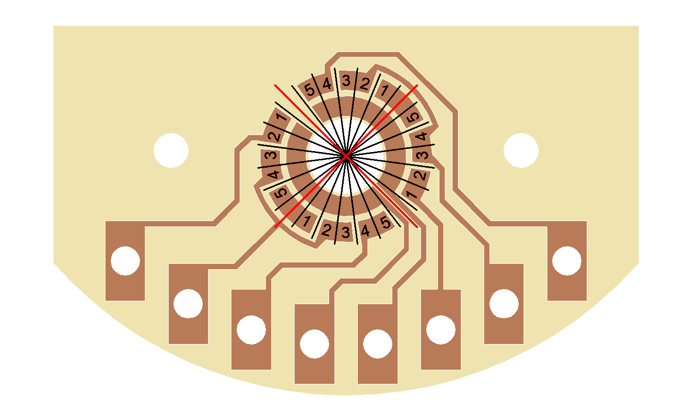
I agree that they're all 'better' than the original -- and, in a vacuum, the latter alternatives with the repeating pattern are best -- but unfortunately the 'standard' has been set to that of "adjacent pole terminals" by the vast majority of cheap import switches, so I think we should at least try to stick to that, rather than proliferating alternatives. I'm somewhat surprised because this would be quite a boon for the marketing department, the switch would be an 'upgrade' from other 'inferior' import switches as a direct terminal-for-terminal replacement. Although, I suppose that boon is balanced against 'locking' customers into a new 'proprietary' terminal layout.
Any particular reason, other than expense? And given another situation where a standard superswitch wasn't enough, what would you use instead? Or, would you rework the wiring scheme so an alternative (less complex) switch could be used? |
|
|
|
Post by frets on Jun 21, 2020 11:58:13 GMT -5
Hi Yogi,
The switch’s cost is not warranted from a consumer perspective given its overall cost to benefit. Working with the double wafer is quite cumbersome. A Superswitch or Standard 5-Way with an auxiliary switch would be preferable from a practical wiring perspective. Simplification of the switch so that the need for the second wafer were eliminated with the same available configurations seems plausible. Lastly, the dimensions of the switch are such that I can envision it not fitting in all cavities without cavity modification. Perhaps EYB will simplify the switch to one wafer.
|
|


 (I don't know what advantage is gained by having the terminals laid out in a way that doesn't follow that of a typical import switch.)The Japanese import strat 5-ways have three 'rings' of stationary contacts. They use just two moveable contacts that bridge between these rings and bridge between all three rings in the positions where there are three contacts being made. I haven't dissected one of these, but I think the moveable contacts are of 'bent metal spring' design.


