cmscss
Meter Reader 1st Class
 Ad-free Angel
Posts: 78 
Likes: 2
|
Post by cmscss on Jun 26, 2020 15:39:11 GMT -5
Hi There, I can solder but my electronics knowledge is crap sorry. I was wondering if someone with knowledge could help me with the following wiring:  I'm having a lot of trouble understanding how to wire this up sorry. Kill Momentary/ToggleI'm hoping there's a wiring solution where the Kill toggle will allow normal operation (kill the signal when the momentary is pressed) or the opposite, where the signal is dead but pressing the kill switch will allow the signal to pass? Series Momentary/ToggleI love the sound/volume boost of the PUs in series so am hoping there's a way to have the Momentary engage series in any pickup selection, with the toggle reversing this so that the guitar is in series with the Momentary engaging parallel? 3-Way PU SelectorAs shown in the diagram, the middle selects both pickups in parallel like a Tele (have I got that right?). And based on my last wiring adventure, the lugs for the 3 way are wired like this:  I realise I know nothing so sorry if this is impossible or painful. I completely understand if it's too time consuming to work out so any pointers in the right diection would be much appreciated. Cheers Ben |
|
|
|
Post by newey on Jun 26, 2020 16:15:45 GMT -5
Your diagram depicts the momentary switches as simple SPST Off-(On). With this type of switch, pressing the button simply makes a connection when pressed, and disconnects when released. It will work for a kill switch, but you would not be able to alter its action as you suggest without having additional switch poles.
Same issue for a series/parallel, but I'm having even more trouble envisioning how that would work. Let's let others chime in.
|
|
cmscss
Meter Reader 1st Class
Ad-free Angel
Posts: 78
Likes: 2
|
Post by cmscss on Jun 26, 2020 16:26:38 GMT -5
Your diagram depicts the momentary switches as simple SPST Off-(On). With this type of switch, pressing the button simply makes a connection when pressed, and disconnects when released. It will work for a kill switch, but you would not be able to alter its action as you suggest without having additional switch poles. Thanks for the reply. Actually, I also have these switches that have more lugs - could they work? www.digikey.com/product-detail/en/nkk-switches/LP0125CCKW01A/360-2526-ND/2105102 "Same issue for a series/parallel, but I'm having even more trouble envisioning how that would work. Let's let others chime in." Let me clarify. I currently have a toggle which engages series in any pickup position. I'm hoping this can be moved to the momentary switch, then have the toggle reverse the function. e.g. 1. With the toggle switch up, the pickups are in parallel as per usual so pressing the momentary engages series. 2. With toggle down, the pickups are in series and pressing the momentary switches engages parallel instead. 3. Then I'm hoping to repeat this arrangement for the kill switch. With the toggle up, pressing the momentary switch kills the signal like a normal kill switch. But with the toggle down, there's no signal unless I press the momentary switch. Does that make more sense? Cheers |
|
|
|
Post by Yogi B on Jun 27, 2020 2:33:58 GMT -5
Let me clarify. I currently have a toggle which engages series in any pickup position. I'm hoping this can be moved to the momentary switch, then have the toggle reverse the function. e.g. 1. With the toggle switch up, the pickups are in parallel as per usual so pressing the momentary engages series. 2. With toggle down, the pickups are in series and pressing the momentary switches engages parallel instead. With the toggle down, do you still want the 3-way switch to select pickups only in (the momentary) parallel mode? I assume that's you intention, but I can't be sure. The kill momentary needs to be at least a SPDT on-(on) switch, your current series-overide switch is presumably a DPDT toggle and the momentary version shouldn't require anything more complex: so yes, a pair of DPDT on-(on) switches should have you covered. Now, on to the toggle switches: the kill toggle only needs to be a SPDT, so using half of the DPDT you indicated on your diagram is fine; however, for the series toggle a DPDT probably isn't going to be enough, you are likely going to need a 4PDT. |
|
cmscss
Meter Reader 1st Class
Ad-free Angel
Posts: 78
Likes: 2
|
Post by cmscss on Aug 9, 2020 16:29:47 GMT -5
Firstly, thanks for your help and sorry for the delay. I'm back onto this project.... With the toggle down, do you still want the 3-way switch to select pickups only in (the momentary) parallel mode? I assume that's you intention, but I can't be sure. If you mean the pickup selector switch should function identically when either the parallel toggle or momentary is used, then yes. I've updated the diagram and while I had a go myself, I got confused very quickly and thought it easier/less confusing if I posted a clean image. How would I wire this up? Sorry if it's a lot of work, any help is much appreciated as I have a hard time understanding electronics sorry. Cheers Ben  |
|
|
|
Post by Yogi B on Aug 9, 2020 21:15:27 GMT -5
Organising this as per your wiring diagram will take a little while, but for now here's a schematic of what I'm thinking: |
|
|
|
Post by newey on Aug 10, 2020 5:41:07 GMT -5
Just so we're clear here, setting the 4PDT to series (momentary parallel) bypasses the 3-way switch, so that both pikups are in series regardless of the 3-way setting, correct? (as opposed to having the series setting only available when the 3-way is in the center position)
If that is the case, the schematic looks good to me.
|
|
|
|
Post by sumgai on Aug 10, 2020 10:52:04 GMT -5
newey, Yes, cmscss did state early on that he wanted 'series override', not 'selector-specific'.
Yogi, I too, see a winner in your diagram. 
cmscss, Yogi's schematic gives you everything you wished for. If you must, wait for a 'wiring diagram', potentially from Yogi or possibly from another member. But just for drill, why not take another chance on doing it yourself?  Simply, and very carefully, follow each wire shown, then trace it/them onto your blank template. One suggestion though, if you do take this step: Rotate the 4PDT on the drawing 90°. As currently shown, the switch handle moves sideways, and that makes things difficult to translate to "switch handle up" or "switch handle down". Beyond that precaution, I'd say: Have Fun!  HTH sumgai |
|
cmscss
Meter Reader 1st Class
Ad-free Angel
Posts: 78
Likes: 2
|
Post by cmscss on Aug 10, 2020 17:22:08 GMT -5
Well, after several hours, I don't understand how to translate this into a layout sorry. e.g. 1. How to I work out which contacts to use on the switches? My 4PDT has 12, the DPDT has 6 and the momentariness also have 6 contacts? 2. For the pickup selector, do the wires come in at point 2 on both sites, and contacts 1 and 3 are bridged (depending on the side)? EDIT: I've had a go but I'm sure you can all tell that I'm completely lost sorry!  |
|
|
|
Post by sumgai on Aug 11, 2020 20:14:17 GMT -5
cmscss, Yes, I can "verify' that you are indeed lost.  But that's why we here, to act like St. Bernards, only the cask won't be filled with Brandy, but instead with help. Let's break this down to little pieces, and start with the simplest thing possible. For now, I want to concentrate on the Kill momentary switch. Nothing else will be used or even touched for the rest of this discussion. The momentary switch you're using is overkill, electrically speaking, but you already own it, so you save money. Bonus! But we'll need only one set of pins, and I've chosen to use the upper three as a set. (This set is what we call a "pole". Your switch has two such poles.) Basically, all we want to do is ground out the hot lead (the one containing the signal), and doing so will kill all output. In simple terms, we turn on the switch to make the connection, and turn off the switch to break the connection. On is "kill engaged", off is "kill disengaged", or full sound output. Got that? Easy, wasn't it. EDIT: Part of this paragraph has been superceded by my Reply #11, below. Now for the hard part. I want you to take the single pin in the center of those three (it will be labeled "Common"), and hook it up to ground. Take the pin to the right, because it will be the pin that connects to the Common when the button is depressed, and hook that up to the "reversing switch". At this point, you've not done anything that we can prove works, but like I said before, we're doing this a simple step at a time. When you've got that drawn into your blank template, post it and we'll go on from there. HTH sumgai |
|
|
|
Post by Yogi B on Aug 11, 2020 20:57:58 GMT -5
Now for the hard part. I want you to take the single pin in the center of those three (it will be labeled "Common"), and hook it up to ground. Take the pin to the right, because it will be the pin that connects to the Common when the button is depressed, and hook that up to the "reversing switch". You might want to check the datasheet for those switches -- their terminal layout doesn't follow the usual 'middle is common' arrangement that you're assuming, but on the plus side (according to the digikey 360° product images) the weird layout is actually labelled on the switch itself: |
|
|
|
Post by sumgai on Aug 11, 2020 21:24:21 GMT -5
Yogi, The datasheet you linked was one I'd already found. I do note that there is no actual pinout diagram, for whatever reason that might be. But I also noted that the manufacturer stated, rather clearly, that the markings were on the casing for each pin. Still, you're correct, I made an incorrect assumption, and it's now backfired on me. 
cmscss, EDITed to add: I just realized that I'm using "pin" and "terminal" interchangeably. Bad form, that's true.... but I'm too lazy to go back and change it all to one way or the other. You need to ignore the instructions I previously posted. Do this instead: For the Common terminal, use the upper-left-most terminal as shown in your blank template - this will go directly to ground. (In Yogi's image, this is the lower-left-most pin - the image is rotated 90° from what you drew in your template.) For the wire that goes to the reversing switch, use the "center" terminal of that pole (set of three pins, remember?) - that is, the pin labeled "NO" in Yogi's image. The circles he's drawn in show where you should be able to find the label on the casing. "NO" is short-hand for "Normally Open". (And "NC" is short-hand for "Normally Closed".) When we say "Normally", we are speaking as if the button is not depressed. Think of it as the internal spring is holding the button upwards (or outwards, if you wish). When the button is depressed, the NO is no longer "normal", the connection is now closed, and thus the signal will be grounded through these two pins, rendering all output null and void. The NC pin will come into play when we hook up the rest of the reversing switch - stay tuned! HTH sumgai |
|
cmscss
Meter Reader 1st Class
Ad-free Angel
Posts: 78
Likes: 2
|
Post by cmscss on Aug 12, 2020 21:36:01 GMT -5
Thanks guys, give me a few days to digest your answers and get my head around things.
Cheers!
|
|
cmscss
Meter Reader 1st Class
Ad-free Angel
Posts: 78
Likes: 2
|
Post by cmscss on Aug 16, 2020 13:55:10 GMT -5
Thank you for the instructions, very very helpful - below are the results as I've interpreted them. I'm totally lost as to where to connect the Kill Momentary but after re-reading the instructions, we didn't get that far - right? Is there a continuity test I could perform on the 4PDT to understand its poles or is it a standard switch? There's nothing written on the casing that seems to explain things (that I can see) but here's the 4PDT switch I have and I didn't understand the spec sorry: www.jaycar.co.nz/4pdt-mini-toggle-switch/p/ST0506Thanks again guys, your patience is very much appreciated. Cheers Ben  |
|
|
|
Post by sumgai on Aug 16, 2020 16:49:05 GMT -5
cm, Your latest does exactly as I instructed, good going! But you're also correct, so far there is no way to test the results in a real-world situation. A meter (that reads Ohms) could tell you what's happening, but that's not the real-world, so I didn't go that far. BTW, do you have any kind of meter at all, in your tool kit?  I'll be back with the next step in a few bits, but right now I'm eating lunch, and when that's done, I'll have to go back to my "day job" - finishing up odds and ends of our long-running house remodel.  Last week it was electrical and plumbing, this week it'll be hanging sheet rock, then mudding it up and finally painting the stuff. Texture will come some time next year, I still have a lot to do outside of this place, getting it ready for the winter.  Stay tuned! sumgai |
|
cmscss
Meter Reader 1st Class
Ad-free Angel
Posts: 78
Likes: 2
|
Post by cmscss on Aug 16, 2020 16:54:33 GMT -5
Thank you for your help and yes, I have a multimeter. No hurry, just when you get time. Cheers
|
|
cmscss
Meter Reader 1st Class
Ad-free Angel
Posts: 78
Likes: 2
|
Post by cmscss on Sept 2, 2020 17:03:50 GMT -5
Sorry for bumping this, just wondering if anyone could help with the next stage on this? And sorry I don't understand what I'm doing, any help would be much appreciated.
|
|
cmscss
Meter Reader 1st Class
Ad-free Angel
Posts: 78
Likes: 2
|
Post by cmscss on Sept 23, 2020 0:01:37 GMT -5
As above - sorry!
Happy to do it one wire at a time if that's easier/less time consuming. Or can I pay someone to help me?
Cheers
|
|
|
|
Post by newey on Sept 23, 2020 6:32:46 GMT -5
cmscss-
Sorry, sumgai was the one helping you here, and he seems to have dropped off the board over the last couple of weeks. Presumably, real life has intervened . . .
Let me take a look and I'll see if I can "pick up the thread" here. May be a day or so before I can get to it, however.
|
|
cmscss
Meter Reader 1st Class
Ad-free Angel
Posts: 78
Likes: 2
|
Post by cmscss on Sept 23, 2020 9:43:26 GMT -5
All good, no need to apologise - I'm the one asking for help!
Cheers, much appreciated.
|
|
|
|
Post by rogerioprazeres on Sept 24, 2020 19:47:47 GMT -5
I will try to help... The kill switch is easy... Just short-circuit the output to ground. You can add a kill switch to any guitar using two wires from the jack without messing with the original circuit. So lets focus in the main problem... The Serie override. Since you want a instant serie option, it must happen "before" the pickups signals go to the switch. It has to bypass all the switching. You will have to decide if you want to bypass the volume and tone controls too... I'm going to make a little draw to help us to understand whats is needed... Hold on!  |
|
|
|
Post by rogerioprazeres on Sept 24, 2020 20:25:41 GMT -5
All good, no need to apologise - I'm the one asking for help! Cheers, much appreciated.  Something like this. Now we just need to figure out the serie override "module". |
|
|
|
Post by sumgai on Sept 24, 2020 21:13:15 GMT -5
cm, Sorry, real life is interfering something awful just now. I'm happy to let roger take over, but don't hesitate to ask questions, should you feel the need to do so. Others, such as newey, were only being 'polite' and not jumping in when it appeared that I might have a plan on how to get you up and running. I do, but it's not my destiny to keep my promises just now. Sorry 'bout that.
roger, Please feel free to offer up whatever help you can, and hopefully you and cmscss will make it all work out to his satisfaction. sumgai |
|
|
|
Post by rogerioprazeres on Sept 24, 2020 23:30:57 GMT -5
I think this will do the trick for a while.  You have to make sure if you want both instant and toogle series switchs in that guitar. It is a lot of contacts to fail... I may suggest you to keep the main blade 3-way switch and only 3 controls in the positions of the original pots (instant kill, toogle to series "override" and volume). It would look very clean and functional. |
|
|
|
Post by rogerioprazeres on Sept 24, 2020 23:45:21 GMT -5
cm, Sorry, real life is interfering something awful just now. I'm happy to let roger take over, but don't hesitate to ask questions, should you feel the need to do so. Others, such as newey, were only being 'polite' and not jumping in when it appeared that I might have a plan on how to get you up and running. I do, but it's not my destiny to keep my promises just now. Sorry 'bout that.
roger, Please feel free to offer up whatever help you can, and hopefully you and cmscss will make it all work out to his satisfaction. sumgai Thank you. Sorry if I was intrusive in anyway. English is mot my native language, so sometimes I'm not able express myself in the proper way. Hope everything is gonna be all right soon. Best regards! |
|
|
|
Post by rogerioprazeres on Sept 25, 2020 7:32:43 GMT -5
By the way, the Yogi B seems to works very well to me. And it and covers all original functions. Very impressive work! I think it is just very difficult to draw and to make work inside the guitar, even for an experienced person. You may want to take two steps back and do a simple version... A standard 3-way, a low profile kill button, a very smooth DPDT toggle and a standard Volume pot. In this way, nothing is going to be in the way while you trying to reach the controls and the guitar will be very intuitive to play. 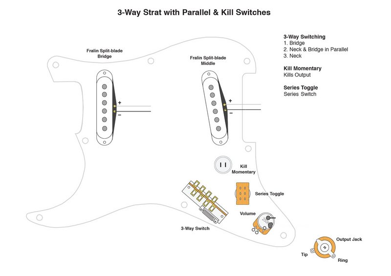 The circuit would be way simple:  The play/kill toggle function is interesting too. You can do that in a push-pull pot in the volume. Just copy the end of Yogi B circuit. Hope it helps! |
|
|
|
Post by newey on Sept 25, 2020 12:18:16 GMT -5
rog-
YogiB's schematic has "got the goods", so to speak, and your diagram is likewise helpful. I believe the problem is that cmscss is not "fluent" in Schematic. He'll need one of us to "connect the dots" for him.
cmcss-
Our philospohy around here is that everybody does better if they take a stab at a wiring diagram themselves, and let us vet it. You will then start wiring the project with a better understanding of how the scheme functions, which will make your build go smoother, and will help if you need to troubleshoot things after you're done.
You've already started in that direction with your Replies #8 and 13, and since then some added direction has been given. So, at this point I would say, why don't you take another stab at a diagram, starting from what you have and incorporating the later info given.
If that is too daunting, one of us will get a diagram up eventually. For my part, it would be next week at the earliest as I'm firing up the Harley and hitting the road with some friends this weekend.
|
|
cmscss
Meter Reader 1st Class
Ad-free Angel
Posts: 78
Likes: 2
|
Post by cmscss on Sept 30, 2020 1:40:21 GMT -5
Firstly, thanks so much for the posts and the work, very much appreciated.
Secondly, you’re right, my brain isn’t wired for this stuff sorry. I think a huge obstacle is understanding where to hook things up - there are a lot of terminals and I don’t understand why sorry - the switch controls are simple!
Is there a methodology for working out what terminal does what? I do have a multimeter if that helps.
And sorry if this is easy.
Cheers
|
|
|
|
Post by newey on Sept 30, 2020 6:38:16 GMT -5
Is there a methodology for working out what terminal does what? I do have a multimeter if that helps. You use the multimeter, set to measure resistance (Ohms), and check from terminal to terminal for each position of the switch. However, while it is recommended to do so in order to assure that a switch is properly functioning before installation, it is not necessary to do so simply to understand how a switch works, as the "switch logic" is either well-known, or published by its manufacturer in a "data sheet". In checking, if you get an "infinite resistance" or "out of range" reading on the meter, the two terminals are not connected; a reading of either 0Ω, or of a very tiny (i.e., maybe 1-2Ω) resistance, means they are connected. For example, earlier in this thread, there was discussion of the unique switch logic of the momentary switches you are using, with yogiB using the datasheet to correct sumgai's misidentification. So, how those switches operate should be clear now from that discussion (and the switches are apparently labeled as well). But I would certainly check them with the meter to be sure, not how they work, but that they are in fact working as they are supposed to do. As for the DPDT switches, the operation of these is easily described. Each pole has 3 terminals/lugs; the center lug of each triplet is the common one, which connects to the lug above it in one position, and to the lug below it in the other. (Note that in a toggle switch or a lever switch, the position of the toggle or lever will be opposite to the lugs being connected) For example, here is how a push/pull pot operates. Your DPDT toggles will be the same, except for the lever vs. the pulling up of the pot stem:  Your previous posts already detail how your 3-way lever switch operates. |
|
|
|
Post by rogerioprazeres on Oct 1, 2020 9:32:22 GMT -5
Firstly, thanks so much for the posts and the work, very much appreciated. Secondly, you’re right, my brain isn’t wired for this stuff sorry. I think a huge obstacle is understanding where to hook things up - there are a lot of terminals and I don’t understand why sorry - the switch controls are simple! Is there a methodology for working out what terminal does what? I do have a multimeter if that helps. And sorry if this is easy. Cheers Most mods in guitar wiring is just about switching, so a multimeter with continuity test (beep) is a very good start. Make note what is connect to what in each positions and you will start to understand. Please do not get me wrong or discouraging, but I truly recommend to star with a simple circuit. Make it work first ad enjoy it for a while. If you try to wire that complete circuit it can be very frustrating and you will probably damage the components with the solder iron before accomplish the final result. If you wanna to go for that simple version I'm proposing, I can draw it for you in the easy mode (visual representation of the wires). Regards! |
|


 Simply, and very carefully, follow each wire shown, then trace it/them onto your blank template. One suggestion though, if you do take this step: Rotate the 4PDT on the drawing 90°. As currently shown, the switch handle moves sideways, and that makes things difficult to translate to "switch handle up" or "switch handle down". Beyond that precaution, I'd say: Have Fun!
 But that's why we here, to act like St. Bernards, only the cask won't be filled with Brandy, but instead with help.


 Last week it was electrical and plumbing, this week it'll be hanging sheet rock, then mudding it up and finally painting the stuff. Texture will come some time next year, I still have a lot to do outside of this place, getting it ready for the winter.


