|
|
Post by ourclarioncall on Jul 26, 2020 20:34:20 GMT -5
Anyone care to share an overview or history of attempts to get the extra 6 sounds ? by that I mean
(neck * middle) + bridge
(neck * bridge) + middle
(middle * bridge) + neck
(neck + middle) * bridge
(neck + bridge) * middle
(middle + bridge) * neck
has any circuit managed to achieve all 6? Or to be more specific , has any circuit been able to get these 6 aswell as the 4 parallel and 4 series sounds and the 3 individual single coils
|
|
|
|
Post by JohnH on Jul 26, 2020 21:06:04 GMT -5
|
|
|
|
Post by ourclarioncall on Jul 26, 2020 22:03:36 GMT -5
Brilliant read, I actually read it yesterday I think, but just had another look through it again A quote from ChrisK “ NanooMan Glad to see that you're interested. Complete solution sets have existed for both a 3 throw version sans phase (+PARALLEL, OFF, +SERIES that uses three each of an 8P3T rotary switch) and a 5 throw version with phase (-PARALLEL, +PARALLEL, OFF, +SERIES, -SERIES that uses three each of an 8P5T rotary switch). I took unk's basic 4P3T Center-ON toggle switch version and extrapolated it to complete solutions with full positional inheritance from the other pickups sometime around Feb07. Here is the post for the The HSS All Mode 'Caster which implements the 5 throw design.” —- So it’s been done , but with rotary switches? I just had a look and can’t find any 8p3t toggle switches nor any 7p3t or 6p3t. If there is such a thing. So as far as with just switches go, one of the biggest GN2 mountains has yet to be climbed . Exciting 😄 . Who will be the first to achieve it Here’s an idea— It would make life much harder than having a single 8p3t Rotary, but could you use TWO 4p3t on-on-on switches together side by side? If that makes sense. Maybe you could create some sort of device that makes both switches move at the same time as if it were one big 8p3t switch. Maybe solder/weld a piece of metal to both switches. This could Maybe be a step closer to an all toggle switch all pickup combo circuit |
|
|
|
Post by reTrEaD on Jul 26, 2020 23:09:55 GMT -5
One part of his work that never made it to that thread was something that's buried in another thread. Using superswitches for each pickup to determine if it's on or off, in-phase or out-of-phase and whether it's placed the series loop or the parallel loop. So basically one superswitch per pickup. guitarnuts2.proboards.com/post/8597/thread |
|
|
|
Post by JohnH on Jul 27, 2020 2:47:19 GMT -5
If you choose to climb that mountain, be sure to take a selfie.
but damn! you've gone and gotten me thinking again...
If I had to do it, I think I'd tackle it with two ideas:
1. Our basic BM series/parallel circuit, with three singles, on/offs and a 4pdt for series parallel
2. We know how to use a dpdt on-on-on with two coils, to get series/single/parallel
then:
3. In the main circuit, what are currently dpdt switches for on/off, would become 4pdt. One half would be exactly what the current dpdt's do. The second half of each would have the pickups direct to them, if the pickups are 'on' they send the connections into the main circuit as usual. But any pickups that are 'off' are flipped over towards the extra dpdt on-on-on, where there get combined in parallel.
Now we have two 'mega pups' one is what would be the usual series or parallel combo for the base design. The other is a parallel combo of all the 'off' pickups (which might be just one of them).
This extra switch then, in its center position, just delivers 'mega pup 1' being the main all-series or all-parallel options as before with no quirks. But if it is 'up' or 'down', it will add the 'off' pickups (megapup 2) to those of 'megapup1' in series, or in parallel, hence allowing all mixed combos to be derived.
There's probably an extra dead spot, if there's nothing in 'megapup2', and it is put into series with the on-on-on. But lets just embrace that as a cool 'kill switch' setting.
|
|
|
|
Post by ourclarioncall on Jul 27, 2020 8:21:16 GMT -5
JohnHI’m on the edge of my seat now 😄 tell me MORE 🤣 A lot of folks died trying to climb Everest , I think I will stay at the bottom and encourage the more experienced climbers 😉😄 I’m glad to stir up and inspire a steady flow of fresh headaches and fun puzzles 👌
|
|
|
|
Post by JohnH on Jul 27, 2020 8:41:33 GMT -5
I'm out of words to explain it more , it obviously would be better with a diagram, which would be subject to having time to do one.
Is this something you might want to build? or just exploring ideas? (that's OK too)
|
|
|
|
Post by ourclarioncall on Jul 27, 2020 9:06:46 GMT -5
I'm out of words to explain it more , it obviously would be better with a diagram, which would be subject to having time to do one. Is this something you might want to build? or just exploring ideas? (that's OK too) For me, having all possible 17 combinations in a circuit with mini toggle switches would be the ultimate (preferably with oop options too) .I don’t think I would rest until I had them all 🙂 my thoughts were maybe If I could not have all 17 in one circuit then I could have 2 guitars with 2 different circuits. One guitar would have your BM design or Andrew Roberts design with variation of it with my volume switches and then I might drive you guys Nutz sowing the seed of a circuit that offers just the final 6. Not sure how hard that would be . So yeah, one guitar would have the 11 sounds and the other guitar the 6. But all 17 in one circuit would be phenomenal I’m just in the process of wiring up your BM design at the moment as I just moved from exploring 2 pickups to 3. I like some of the other designs that offer 3 of the final 6 (the mixed series and parallel settings) but I wouldn’t build them unless there was all 6 As i prefer your BM version that has logical easier to remember switching. But for all 17 sounds I wouldn’t be too fussy on having the switching perfect and logical and everything clean . It would just be great to have all 17 in a guitar with mini toggles and not 5ways or rotaries. I wouldn’t mind paying big money for switches either. Nor is space in the cavity an issue. I think that I would/will use mini toggle circuits when playing live or teaching or bedroom playing , these won’t be a studio or experimental circuits for me they will be my everyday everywhere go to. |
|
|
|
Post by ourclarioncall on Jul 27, 2020 10:40:49 GMT -5
JohnHjust took time to re-read your concept again, wow, that would be amazing, especially being able to keep the simple functionality of the original BM design. Love the idea If out of phasing is possible I guess they would be on separate 2pdt switches
|
|
|
|
Post by newey on Jul 27, 2020 12:11:36 GMT -5
But all 17 in one circuit would be phenomenal Understand that some of these combos will sound very similar, and, depending on the sorts of pickups used, may be indistinguishable from one another. As has been said here many times, these "all-everything" guitars are useful as a technical exercise, but not all that practical for day-to-day use on stage or in studio. They quickly become too "switchy", meaning one cannot easily find the combo one wants, and many of the selections will sound the same, and will therefore seem redundant. If you build such a guitar, you will find certain "go to" combos that you use frequently; most of us then end up building a much simpler guitar to incorporate only those tones we use regularly, and to make them easy to get to. |
|
|
|
Post by ourclarioncall on Jul 27, 2020 12:33:27 GMT -5
But all 17 in one circuit would be phenomenal Understand that some of these combos will sound very similar, and, depending on the sorts of pickups used, may be indistinguishable from one another. As has been said here many times, these "all-everything" guitars are useful as a technical exercise, but not all that practical for day-to-day use on stage or in studio. They quickly become too "switchy", meaning one cannot easily find the combo one wants, and many of the selections will sound the same, and will therefore seem redundant. If you build such a guitar, you will find certain "go to" combos that you use frequently; most of us then end up building a much simpler guitar to incorporate only those tones we use regularly, and to make them easy to get to. Thanks Newey. Yeah, good points to bear in mind. I have already processed the possibility of the extra 6 sounds not being that great or not being my favourite go to’s. But I’m maybe a bit weird , that I would just get a thrill out of knowing I have them all , preferably In as clean and functionaly logical a circuit as possible. But who knows, maybe i will love them or at least one - (B*M)+N 🙂 I think if I could have all those sounds now in a mini toggle circuit BUT there were tons of dead spots/redundancies and too many switches , I would not build it. Even if it offered all the sounds. So yeah, it’s a bit of a balance between logical function/switch count/available sounds. Cost doesn’t bother me personally nor does cavity size. |
|
|
|
Post by JohnH on Jul 27, 2020 15:16:44 GMT -5
OK, so it seems like this idea could work out, and that the issues of its complexity are understood. ill draw it.
yes, it might as well have all the phase switches too, although you could save one phase switch and put the extra on-on-on there if you wanted.
The general flow would be for each pickup:
pickup wires,
to phase switch,
to this new extra half of the on/off switch -
into the main BM series para circuit
out of the BM circuit
into the new on-on-on where it meets pickups that were 'off'
volume and tone pots
From other guitars, I think there are a few genuinely useful mixed combos on an SSS guitar, assuming that you have a standard not-noiseless set with an RWRP middle pu
If you put B and N in series and then add M in parallel with it all, its similar to M but humcancelling
B and M in parallel, then all in series with M is also humcancelling, and its loud like other series combos but not muddy since its inductance is x1.5 instead of x2
If you start using the phase switch you can find several other humcancelling mixes, eg B and M out of phase in series, all in parallel with N, sounds like an edgier but non humming N
|
|
|
|
Post by ourclarioncall on Jul 27, 2020 19:58:41 GMT -5
JohnH Great stuff, look forward to seeing how you get on 👍 👍 I think I would really like the mixed combos. I like subtle shades . The ability to have a sound that’s close but a little different. The ability to lose one of the phase switches is handy. As I could use the the extra space that creates for a master volume . I like symmetry , I’d rather have 8 switches than 7 😁. But ... I’m wonder if it would be a bit easier to follow with the 3 phase switches as I may get confused, but even more importantly, the series /off/parallel switch would feel more logical and memorable being directly in line with the other series /parallel switch. Like below . Either way doesn’t matter too much just whatever works for you drawing it out. I can always tweak it come time. I remember reading something about Brian May rewiring his guitar so that the neck or bridge was RWRP so that his favourite go to tones were hum cancelling. Not sure if I’m getting the story right or if it’s even accurate but what you were saying jogged that memory 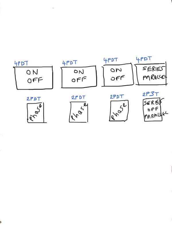
|
|
|
|
Post by JohnH on Jul 31, 2020 23:42:11 GMT -5
As the Dalai-lama said when he walked into a burger joint: "make me one with EVERYTHING... " Here it is: 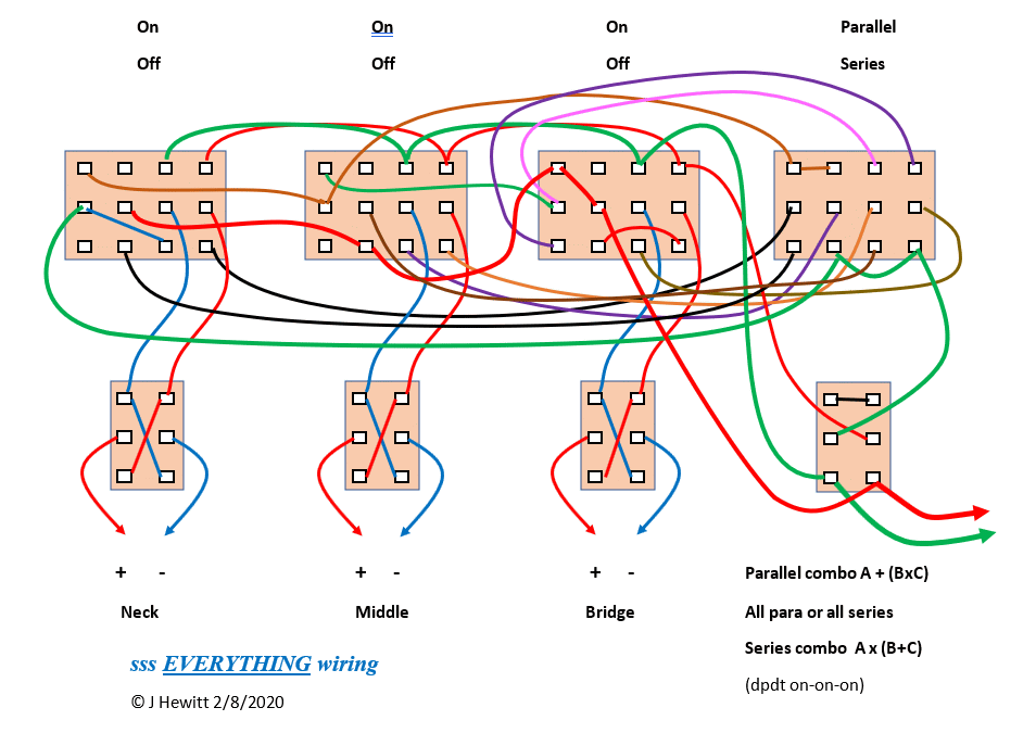 It is the BM sss design for series and parallel, with an added on-on-on so that any pickup or pickups that is not in the main combo can be added in series or in parallel overall. With this added switch in its middle position, it should just be the main combo and as the original design. This was the base design: guitarnuts2.proboards.com/thread/4855/brian-series-parallel-switching-sssOn each on/off switch, two poles are added being the right hand two. So there are four two position 4pdt switches. In view of the fact that it is clearly an insane rats nest, I split the wiring into two images. Here's the added wiring to make the extra combos work:  And this is the wiring associated with the original core design: 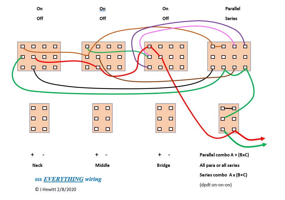 This part of the wiring was copied over and I haven't attempted to flip it upsidedown, for fear of a snafu. Ive labeled the switch positions according to the position of the lever on a toggle switch, which connect upwards if the lever is down (previously, the on/offs were assumed to be slide switches which work the other way). The on-on-on has the left side connecting down and the right side up in the middle position. Needs a check before wiring, but I think it should work. (EDIT 2/8/2020 on-on-on fixed per Yogi's post below) |
|
|
|
Post by ourclarioncall on Aug 1, 2020 7:50:32 GMT -5
JohnHjohn! Genius 🤗😃😎😉 that’s fantastic I will get some time later to sit down and look at this properly
|
|
|
|
Post by Yogi B on Aug 1, 2020 18:02:48 GMT -5
As the Dalai-lama said when he walked into a burger joint That's some bohemian Buddhism, but that's probably appropriate for a BHM wiring thread. Shouldn't it be the opposite, or rather since that is the way that the majority of DPDT on/on/on switches work, shouldn't the poles of the switch be swapped? In the centre "core" position, the "core" ground wire should be grounded, whereas the additional 'off/parallel' hot wire should be disconnected.
As for smashing these two ideas together, your original wiring goes out of its way to avoid shunted or hanging coils, however since in this expanded version the pickups are disconnected from the "core" switching when 'off', this is now mostly (if not completely) unnecessary. As such, I reckon the exact switching that is offered here could be done with only three poles of each 4PDT on/off switch. But rather than cut the switches down to 3PDTs, that extra pole could be utilised to eliminate the dead spot that you predicted in your earlier post (i.e. in the mode with the 'off' coils in series with the 'on' coils, but all coils are in the 'on' group). |
|
|
|
Post by ourclarioncall on Aug 1, 2020 18:43:51 GMT -5
I have been pouring over a lot of the BM variations over the last week or so.
I have a bit of a vision for a circuit, and Johns new design has taken me one step closer 🙂
I am up for wiring this and then filming some sound demos with clean and overdrive. I just need to get some more switches. I have a 2pdt on-on-on but have it set up as a full/ two thirds/ one third volume switch. I need to get some more . Got a few 4PDT on-on switches but they need a good clean up and old wiring removed.
I wasn’t going to mention this as I thought it might sound a bit rude /cheeky, but since Yogi mentioned possibly freeing up poles I thought I might throw this idea out there for future consideration. As I said I have been up to the early hours in the morning pouring over what was Yogis tweaking of Andrew Roberts design that evolved in part from Johns.
I like the fact that the pickup switches have the option of out of phase as well as in phase and off. There is a reason I like it which I will get to in a minute.
So today I was trying to see if I could take some of Johns new design and integrate it into yogis. I thought I was on the right track but noticed some major differences and put it on the shelf.
Anyway, what are the chances of tweaking Johns new everything design to have out of phasing also? I guess it would it would need a 4PDT on-on-on if possible . Or perhaps it’s much too difficult to tackle. No pressure to deliver the goods, and I hope i don’t seem ungrateful as I really appreciate John taking the time to come up with this splendid design. If it’s too much work that’s cool 😎
The reason I would like out of phasing added to that specific switch is so it can work alongside another idea, which is to have a half out of phase (hoop) switch for each pickups with two caps in each for the series side and parallel side of the circuit. Actually it’s not really a hoop switch , it’s just a cap on switch or do you call it a cap bypass? So that would give me a variety of new sounds , but then by having the out of phase Option on the pickup switches I could then access the half out of phase sounds. I have a circuit that has done this already for two pickups so hoping it could be done for three.
Any , still dreaming . And trying to squeeze as much functionality out of as little switches as possible .
|
|
|
|
Post by ourclarioncall on Aug 1, 2020 18:54:52 GMT -5
Not only do I want everything, I want more 😂😁 All the sounds , and all of these John kindly shared these possibilities with us on a different thread 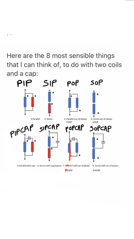 |
|
|
|
Post by ourclarioncall on Aug 1, 2020 19:05:31 GMT -5
I was quite proud of myself as I managed to figure out how to change a hoop switch(bottom picture) into just a cap on /cap bypass switch(top picture) . If I want hoop , I have an Independent oop switch that I can turn to create hoop. What’s nice about this although it’s a bit messy is that I can turn on the caps with one switch , I don’t need one switch for parallel and another for series. And I can have oop on its own , or combine it with cap switch to get hoop. so yeah, just wondering if I could at some point add something like this into Johns new circuit . 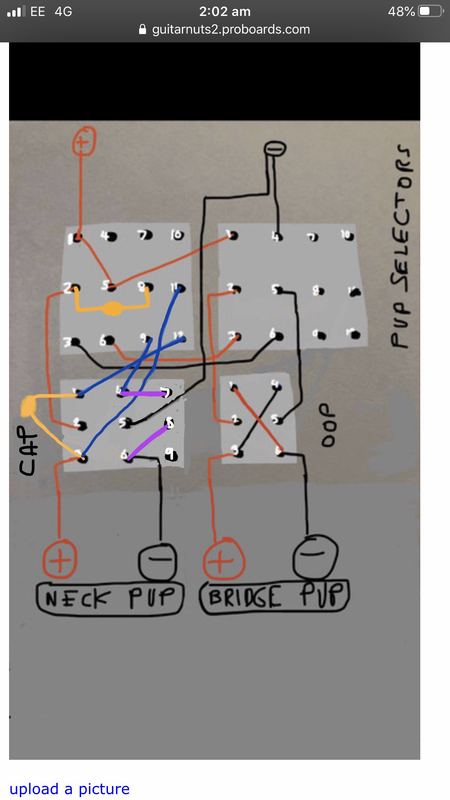 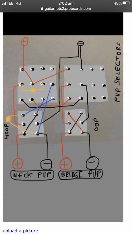 |
|
|
|
Post by JohnH on Aug 1, 2020 19:14:36 GMT -5
The on-on-on has the left side connecting down and the right side up in the middle position. Shouldn't it be the opposite, or rather since that is the way that the majority of DPDT on/on/on switches work, shouldn't the poles of the switch be swapped? In the centre "core" position, the "core" ground wire should be grounded, whereas the additional 'off/parallel' hot wire should be disconnected. Thanks Yogi, I agree about the on-on-on so I fixed the diagrams in my post above (noted at end of post) To strip out a pole, would need a schematic drawn out then a total re-do and re-check. If anyone else suggested it Id be sceptical, but since it was yourself ill agree it might work. But that's not high on my to-do list right now! Happy to talk about it though. |
|
|
|
Post by JohnH on Aug 1, 2020 19:23:55 GMT -5
The reason I would like out of phasing added to that specific switch is so it can work alongside another idea, which is to have a half out of phase (hoop) switch for each pickups with two caps in each for the series side and parallel side of the circuit. Actually it’s not really a hoop switch , it’s just a cap on switch or do you call it a cap bypass? So that would give me a variety of new sounds , but then by having the out of phase Option on the pickup switches I could then access the half out of phase sounds. I have a circuit that has done this already for two pickups so hoping it could be done for three. Yogi is proposing that it might be possible to save one pole, but phase-changing tends to need two poles. So we are at 4-1+2 = 1 more pole than is available |
|
|
|
Post by ourclarioncall on Aug 1, 2020 19:45:53 GMT -5
JohnH no worries mate (*spoken in my Ozzie accent ) you’ve done more than enough , put your feet up and have a rest 😉 im back to work in a week or so, so might be ready to crank up the amp and hear and record how these 6 new tones sounds thanks again for all your hard work 👍
|
|
|
|
Post by JohnH on Aug 1, 2020 19:58:08 GMT -5
You are welcome.
BTW, these tone options tend to go virally exponential, if not 'locked down', creating a 'Tone-edemic'! Those 6 original extra tones become 24 once phase switches start getting flicked!
|
|
|
|
Post by ourclarioncall on Aug 1, 2020 21:26:42 GMT -5
You are welcome. BTW, these tone options tend to go virally exponential, if not 'locked down', creating a 'Tone-edemic'! Those 6 original extra tones become 24 once phase switches start getting flicked! Oh boy , And here was me thinking about what tones you’d get if you went from 3 single coils to 4 😬😐😲 I better put my thinking cap into quarantine before it starts coming up with more contagious ideas |
|
|
|
Post by JohnH on Aug 2, 2020 5:12:42 GMT -5
BTW I went back to the schematic to review if a switch pole can be saved. For the base design, its in the schematic section called Tonemonster2, the same switching idea with just one phase switch.
I was right.....(and I like to be right)
.....I correctly predicted that Yogi is correct and a pole can be saved. (thanks Yogi)
It would be better to make that change, it reduces the number of contacts in line with the signal and slightly simplies the wiring. I will make the change in a few days.
|
|
|
|
Post by ourclarioncall on Aug 2, 2020 13:55:51 GMT -5
BTW I went back to the schematic to review if a switch pole can be saved. For the base design, its in the schematic section called Tonemonster2, the same switching idea with just one phase switch. I was right.....(and I like to be right) .....I correctly predicted that Yogi is correct and a pole can be saved. (thanks Yogi) It would be better to make that change, it reduces the number of contacts in line with the signal and slightly simplies the wiring. I will make the change in a few days. Is there a tone master 1 ? Was the that John Atchleys from GN1 ? I think I looked and couldn’t find it How many Different BM type designs have you done John ? I just looked at a bunch of them from various BM designs over the last week or so , my brain melting trying to remember 🤗 Mr Yogi sounds like a good guy to have around these parts 😉 |
|
|
|
Post by JohnH on Aug 2, 2020 17:26:21 GMT -5
The first 'Tonemonster' was on the old GN site, now mostly lost. But I have this of it, posted on Ultimate Guitar. Im pretty sure its John Atchley's design but maybe not his graphic:  It works a bit differently. The pickup switches are on-off-on, and you select series, off or parallel with them. S4 is the overall series/padallel switch and you select either the series, or the parallel group (not both) With regards to other multi-toggle designs, there were were few others. such as Wolfs on 1728.com, and also Dan Armstrong: ashbass.com/AshBassGuitar/index.html?armstrongstrat.htmlI also have a bunch of Strat designs, mostly with some series and parallel, but in terms of all-toggles, I think you've seen them now. |
|
|
|
Post by ourclarioncall on Aug 2, 2020 17:36:37 GMT -5
JohnH wow, cool, I’ve never seen this before . i used to spend a lot of time in the old GN1 site years ago, it was great. I don’t remember this one tho question- I think it might have been Yogi B ? That mentioned John Atchley had another Version of this that included out of phase , maybe on the same switch ? I’d like to see that one I tried a couple times to look at wolfs ones but the links didn’t work for some reason , not sure if his site is still active ? It probably is , il have another look. and just looked at dan Armstrong one too recently as well as I think UnklMickey And ChrisK. I liked yours the best for the logical switching . I’d rather have more switches/wiring etc and simpler to operate circuit than for the switching to be not so intuitive and harder on the old memory . I love these BM type designs or series/parallel designs in general, they are a great education drawing lines on the switches and tracing through how they work .
|
|
|
|
Post by Yogi B on Aug 2, 2020 17:53:01 GMT -5
BTW, these tone options tend to go virally exponential, if not 'locked down', creating a 'Tone-edemic'! Those 6 original extra tones become 24 once phase switches start getting flicked! Oh boy , And here was me thinking about what tones you’d get if you went from 3 single coils to 4 😬😐😲 I better put my thinking cap into quarantine before it starts coming up with more contagious ideas Oh, it's even worse than exponential growth. Being a combinatorics problem, not unexpectedly, the numbers grow factorially. The 17 selections without phasing (or 47 with phasing) that are possible with three coils become a nice round 100 (or 572 with phasing) when you have four coils. BTW I went back to the schematic to review if a switch pole can be saved. For the base design, its in the schematic section called Tonemonster2, the same switching idea with just one phase switch. I find it easier working backwards from the 4PDT version, figuring out what can switched around until there's two poles that have two connections in opposing positions & share a common terminal, and thus can be combined into one. Doing that I ended up with this: Note that like JohnH's diagram this assumes toggle switches, therefore their labelling is reversed in relation to the actually connected terminals. Additionally the on/off and phase switches have been flipped upside-down with respect to John's diagram. But rather than cut the switches down to 3PDTs, that extra pole could be utilised to eliminate the dead spot that you predicted in your earlier post (i.e. in the mode with the 'off' coils in series with the 'on' coils, but all coils are in the 'on' group). Here's a diagram that does this: |
|
|
|
Post by ourclarioncall on Aug 2, 2020 18:53:33 GMT -5
Yogi Byou guys are brilliant 😃 Thankyou so much I work as a guitar teacher (mainly electric) if you or JohnH Need any help with guitar teaching related stuff, or anyone else on GN2 let me know and I would love to return any help I can. I can make up sheets or make Videos etc.
|
|