|
|
Post by frets on Aug 28, 2020 18:53:50 GMT -5
Dear Guys, I’ve got a wild Cindi sidebar project that I’m working on. It’s miniaturizing effects for placement in an old RG. Why? Just because. Anyway, got my prototypes for Overdrive/Distortion, PT2399 Chorus and Delay back. Just wired up the Distortion one. It sounds really good so I’m posting the diagram for others. It’s an LM386 derivation. Real old Skool sound like an old MXR. It goes on an A100k. Can’t use a B100k. Slope does not correspond with maximizing the distortion at 10 on the sweep. The A100k culminates with a full rich distortion at 10.   |
|
|
|
Post by ourclarioncall on Aug 28, 2020 20:22:42 GMT -5
That’s coowl 😎
I wanted to do stuff like this , day for example, take a tube screamer or compressor pedal any build it into the cavity somehow . I suppose it might eat up batteries tho
|
|
|
|
Post by newey on Aug 29, 2020 7:50:28 GMT -5
I suppose it might eat up batteries tho Just as with active pickups, you can use a TRS "stereo" type jack to cut power when no cable is plugged in, which will help a lot with battery life, provided you're not leaving the guitar plugged in for long periods. We've also discussed the use of rechargeable batteries or external power supplies, although I don't recall if anyone has actually tried either of those options. frets: How is the unit switched in/out? |
|
|
|
Post by frets on Aug 29, 2020 15:24:29 GMT -5
Hey Newey, Right now I have an on/off switch to it. But I just revised my AutoCad file to use a Chinese green mini switch pot. And ordered five off of AliExpress If it were on all the time with the pot turned to “0”, it would most likely eat juice. I’m still at a loss on how to power all 3 (Distortion, Chorus, Delay). But I have plenty of time to research as my Chorus and Delay came back too big. I have to move to smaller caps and resistors and rotate. The boards do work though.  |
|
|
|
Post by unreg on Sept 3, 2020 11:38:03 GMT -5
Wow! frets, that’s really cool!  In your diagram, the line on the right is not simple (straight)... does that change how the distortion sounds? Or is the lengthened/pointed line-extension created just bc it’s more interesting to look at? It looks unique!  edit: Ooh, you put solder spots on that lengthened point. Is that to maybe add more electrical things? Or just made you happier? Sorry, I don’t remember much of EE; could read my textbook. |
|
|
|
Post by frets on Sept 3, 2020 17:07:01 GMT -5
Hi Unreg - thanks for asking,
To tell you the absolute truth, I just got lazy and made junction points between tracks. I’m working on a revising this one to be more compact. It will not have the junction pads. And I built a new board that is more Overdrive than Distortion; and, I’m going to revamp them to go on a switched pot so the circuit can be turned off. The Overdrive is really a good one and I’m hard pressed to make a decision on which will go in the guitar. When I have the Onboard Overdrive circuit designed in AutoCad, I’ll post it to the forum.
The Chorus and Delay boards I’ve cut their respective sizes in half. They are still bigger than the distortion board but will fit inside a Strat cavity. It’s a silly goal but I want to build another beater guitar with volume, distortion (or overdrive), delay, chorus pots - and a two way tone switch at .015 and .022. So 4 pots and a switch. It will run off of a rechargeable with the charging port on the back of the guitar. Completely silly but it will be great to take for busqing sessions with friends.
|
|
|
|
Post by ashcatlt on Sept 3, 2020 18:08:50 GMT -5
...external power supplies, although I don't recall if anyone has actually tried... I mean... |
|
|
|
Post by frets on Sept 3, 2020 18:59:38 GMT -5
You all have to listen to the sound track on this video.🪐
|
|
|
|
Post by unreg on Sept 3, 2020 19:08:48 GMT -5
It will run off of a rechargeable with the charging port on the back of the guitar. Completely silly but it will be great to take for busqing sessions with friends. That sounds amazing. Have you thought of powering this guitar with an iPhone battery? That would be so cool; you could charge it on a car trip to your friends! The iPhone 11’s battery is 3110 mAh, according to the internet search I just did. I’m sure 3110 mAh is too much juice for your circuitry. No, mAh refers to the size of the battery. Sry, you’d have to research its voltage. But, you could create voltage dividers with resistors, a bunch probably, to soften the power flow. Then, since the battery is quite thin, you could sand, or use some other better wood working tool to make, a shallow depression in the back of the guitar to hold the battery, and cover that depression with a plate and 4 screws. You’d have to figure out how to harvest a battery-plug-outlet from an iPhone, to make it possible to plug in the battery. And you’d have to figure out how to install that tiny iPhone charging port. You seem to like to research. But, there’s probably a less complex way to use a rechargeable battery. I’m sorry; just thought it would be so cool to recharge a guitar with an iPhone charging cable! Hope your plans work out; it sounds like it would be very fun. edit |
|
|
|
Post by ashcatlt on Sept 3, 2020 22:53:08 GMT -5
You all have to listen to the sound track on this video.🪐 LOL. That's actually this varispeeded down an octave or so and included to try to mask some of the room noise. |
|
|
|
Post by thetragichero on Sept 4, 2020 1:50:10 GMT -5
hoping you're using an anti latch up on the two pt2399 circuits (especially the chorus)
|
|
|
|
Post by frets on Sept 4, 2020 6:52:28 GMT -5
Trag,
I don’t. They have no transistors and I didn’t even think about latch up. I can put up the design if necessary. I do have a 7805 on the Chorus before the current hits the PT2399.
|
|
|
|
Post by frets on Sept 4, 2020 6:57:08 GMT -5
Unreg,
Thanks for the ideas. I’m thinking about multiple lion methods to power the 3 boards.
|
|
|
|
Post by unreg on Sept 4, 2020 15:41:07 GMT -5
Unreg, Thanks for the ideas. I’m thinking about multiple lion methods to power the 3 boards. You’re welcome frets! Pray about your path and then trust your gut; I feel it will work out. You must be extremely experienced at guitar creation; I’m definitely not adequate at guitar creation (don’t even know what a lion method is). But, happy to “help”. |
|
|
|
Post by sumgai on Sept 4, 2020 18:20:24 GMT -5
(don’t even know what a lion method is). She meant "Li-ion", a short for Lithium Ion. You know, the same type of battery as in your smart phone, and most other rechargeable gear these days. Good stuff. HTH sumgai |
|
|
|
Post by thetragichero on Sept 5, 2020 2:18:11 GMT -5
powering those with a steady clean 5v is important (a resistive divider would wiggle, not a problem biasing an op amp but big problem with pt2399)
latch up happens with short delay times which is what chorus is all about
i love the pt2399 because it's digital and easy to use but still dirty like analog. messed around with cap values on some of the filters and was able to get oscillation and all that other lovely analog goodness
|
|
|
|
Post by unreg on Sept 5, 2020 15:13:56 GMT -5
(don’t even know what a lion method is). She meant "Li-ion", a short for Lithium Ion. You know, the same type of battery as in your smart phone, and most other rechargeable gear these days. Good stuff. HTH sumgai Thank you sumgai! —- Want to note: I was wrong, you don’t need lots of voltage dividers... just scroll down on that page I previously linked too. All you need to have is your voltage supplied, the voltage needed, and one resistor value. Plug those values into the listed equation, solve, and you’ll have the value of the second resistor you need for that voltage divider circuit. You’ll just have to play with the initial value of resistor 1 until you receive workable resistor values. That’s only if the supplied voltage is higher than what you need, but I’m sure that’s the case with lion methods. |
|
|
|
Post by unreg on Sept 5, 2020 16:35:17 GMT -5
Kind note: Make sure that you read the values appropriately. For instance, if you use a resistor #1 value of 10KΩ, then the answer to your equation will be in KΩ. So, if somehow you get 0.5KΩ as an answer, then you would need to use a 500Ω resistor for resistor #2. Since 1KΩ = 1000Ω,
1000Ω * 0.5 = 500Ω In the same way, if resistor #1 is 500Ω, then answer must be in Ω, and so if you somehow receive 10000Ω as a result, make sure you use a 10KΩ resistor for resistor #2. |
|
|
|
Post by thetragichero on Sept 5, 2020 18:44:21 GMT -5
iphone battery is 3.7v according to a quick search?
so you'd need three of em
11.1v if you've speced your capacitors for say 16v is fine. the sensitive parts (pt2399) will be run off a 7805 or similar anyway
more than likely you'll want to look into other options because those batteries are likely expensive. maybe hit up your local thrift store and look at some of the electronics (that's where i get my wall warts at). cordless phone will probably be lower voltage (5v) but you may get lucky
rc car batteries maybe
you can make a lot of stuff work for you
|
|
|
|
Post by frets on Sept 6, 2020 11:32:19 GMT -5
That’s exactly what I have, 3 3.7v Li-ion batteries that I’ve purchased.
|
|
|
|
Post by thetragichero on Sept 6, 2020 11:52:26 GMT -5
wouldn't worry about dropping voltage down to 9v. waste of components, power. doubt you'd use 10v electrolytics anyway. any op amp should be good for 24v minimum. if anything you'll have a tad more headroom before hitting the power rails. would highly advise finding a transistor (any npn should do) for the anti latch up circuit.... might be able to find one in old electronics... old universal remote, old electronic toy, etc
|
|
|
|
Post by frets on Sept 6, 2020 22:35:50 GMT -5
Trag,
I’ve got the Chorus board soldered up and it works surprisingly well for what it is; I.e., “one chip,” but this latching issue has me concerned. I have a ton of NPN’s, are you suggesting one goes in after the 7805?
|
|
|
|
Post by thetragichero on Sept 6, 2020 23:15:30 GMT -5
pin 6 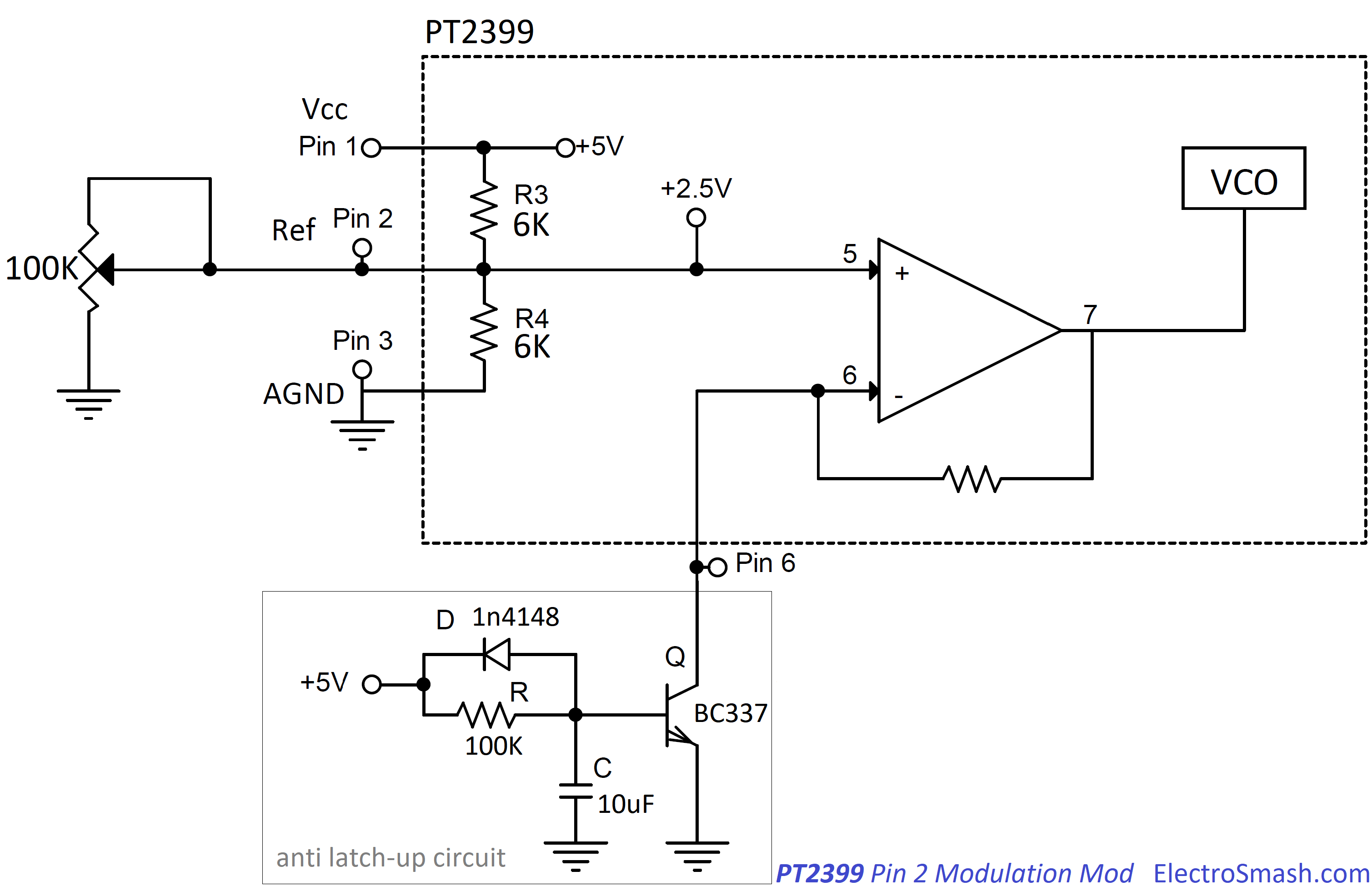 here's more information that you'll probably want: www.electrosmash.com/pt2399-analysisthe jist of it: delay time is set by pin 6 resistance to ground. chorus is a very fast delay time. the chip goes into a protection mode if the resistance to ground is less than a certain number (that page says 2k, merlin says 1k) and the only way to get it back is to power cycle it (which can be problematic if it's installed inside a guitar). that little circuit acts like a slow start up |
|
|
|
Post by frets on Sept 7, 2020 0:29:18 GMT -5
Trag,
This is immensely helpful and actually quite an interesting read. I’m using the 16 pin PT2399 on both the Chorus and Delay. As you know, I’m looking to save real estate and skinny down the chorus circuit. Which I think I’ve accomplished. Therefore, I will squeeze in the anti latch off of pin 6.
Go drink some more suds, you deserve them. Thanks so much for skooling me about this topic.
|
|
|
|
Post by unreg on Sept 8, 2020 12:26:13 GMT -5
here's more information that you'll probably want: www.electrosmash.com/pt2399-analysisthe jist of it: delay time is set by pin 6 resistance to ground. chorus is a very fast delay time. the chip goes into a protection mode if the resistance to ground is less than a certain number (that page says 2k, merlin says 1k) and the only way to get it back is to power cycle it (which can be problematic if it's installed inside a guitar). that little circuit acts like a slow start up As frets said, that was a very interesting read thetragichero! Thank you for your link! Anti-Latch Up sounds like the NES’s start-up... bc when it’s powered on its PPU (Picture Processing Unit) has to warm up and so a programmer has the luxury of two entire frames to init variables and set flags. But, most of that time is spent inside 2 tiny loops doing nothing. —- The pt2399 seems extremely excellent frets! Nice choice! |
|


