|
|
Post by ourclarioncall on Oct 17, 2020 2:43:22 GMT -5
myfenderchamp.com/2010/03/11/fender-champ-5c1-wiring-diagram/This seems to be the simplest tube amp circuit I can find as it’s single ended and has 1 pentode in the preamp instead of dual triode (which I find harder to read and understand on a schematic) Even then, it’s still complicated for me, but seems much more manageable and easier to see the building blocks as it were. Is there any way it could be made even simpler ? For example , what about having only one input instead of two , again , I find those dual inputs a bit confusing, i want to see what one looks like first before trying to understand two. And what about the rectifier tube ? If it were a solid state rectifier would that simplify anything ? Or could the rectifier be cut out all together ? Could we lose the volume pot and just have it full blast the moment it’s turned on ? Can we lose the on switch so it turns on when you plug it into the wall ? My thoughts are that I’m not looking to build this and I’m not looking for a circuit that sounds good, just one that is stripped back to the bare bones for education purposes.
|
|
|
|
Post by thetragichero on Oct 17, 2020 3:04:14 GMT -5
I'd highly suggest looking at a 5f1 instead. pentode preamp tubes are very rarely used these days for a number of reasons. they tended to become microphonic. triodes are a lot easier to understand and more useful for understanding today's amps. power through it
|
|
|
|
Post by ourclarioncall on Oct 17, 2020 3:24:46 GMT -5
I'd highly suggest looking at a 5f1 instead. pentode preamp tubes are very rarely used these days for a number of reasons. they tended to become microphonic. triodes are a lot easier to understand and more useful for understanding today's amps. power through it Can’t we have two single triodes instead of one dual? 😁 that’s a big chunk of schematic confusion for my slow brain . And why have two triodes in one valve? Do you need that ? |
|
|
|
Post by thetragichero on Oct 17, 2020 11:09:18 GMT -5
where's the schematic confusion? they're rarely run paralleled (kind of a waste of a triode) so there are always components and space separating the two triodes on schematics
the reason there are two triodes in one bottle is because it's cheaper all around. cheaper buying tubes, cheaper on sockets, cheaper on heater current for the power transformer, etc. plus then you don't have a high gain Marshall running 12 friggin tubes
wanting to learn about pentode preamps instead of dual triodes because it's "easier" (not even debatable, 5 things going on in each time is more than 3 things per section) reminds me of my friend's mother in high school suggestion we take a COBOL course at the community college to learn programming instead of what was standard at the time, c++ and java. why learn a dead style that you're likely never going to use over industry-standard stuff (at least from start. you wanna look at vintage vox amps with ef86 preamps after you understand what 99% of the amps use that's just hobby specialization)?
|
|
|
|
Post by ourclarioncall on Oct 17, 2020 11:39:00 GMT -5
where's the schematic confusion? The whole schematic is confusion. Every schematic. Even the easiest of easy. But again I have to appreciate I have no foundations in electronics and have to accept reality I suppose that even at the simplest level I’m out of my depth. I liked the idea of the one pentode preamp valve as it’s less “stuff” on a page I have to try and understand . No plans to build these kinds of amps, it’s just my way of trying to get an overview. From teaching guitar I’ve learned that few people will follow a logical systematic method of learning. Often you have to give them what they want even if it’s too big and hard. You want to teach them ABC, but they want to start at Z then go back to K. It’s best to let them take control as you won’t have a battle of wills on your hands and they maintain there motivation even if the progress is twice as slow as it could be. When it comes to this forum, I’m that guy 🤣. I know what I want to find out but often can’t articulate it 😩 |
|
|
|
Post by thetragichero on Oct 17, 2020 12:00:17 GMT -5
it's hard to understand a pentode (five things going on) if you don't understand a triode (three things going on). not to mention that pentode stage is almost assuredly grid leak biased, be which ain't gonna help you with a standard cathode biased triode stage that the rest of the world uses
i understand self-directed learning but this is like trying to learn sweep picking before you understand where to place your fretting fingers
maybe i'm a few decades early being a crochety old man but this ain't actually simplifying things for yourself
read the robinette 5f1 article. reread. take notes. he does a wonderful job illustrating how to follow the schematic
|
|
|
|
Post by sumgai on Oct 17, 2020 13:31:42 GMT -5
occ, OK, I can see that you're not gonna go down the traditional path in your education, so I'm gonna give you the shortcuts you've been (oh-so-subtly) asking for. One, 99% of your questions so far are easily answered by a single word - cost. Cost effectiveness, or cost containment, or any other derivative thereof, it all boils down to the same thing, cost. Two, you need to have some theory to gnaw on. Here it is, wrapped up in historical fashion. We'll begin with Lee DeForest inventing the first control element in a valve, the grid (later named the Audion). This was in 1903! (But not patented until 1906.) The grid's job was to modulate (control) the flow of electrons from the cathode to the anode (plate). This allowed a signal applied to the grid to create ups-and-downs in the plate's voltage circuit, which we interpret as a "better" version (more powerful) of the original signal. In essence, the low voltage from the signal is impressed upon the grid's DC voltage, and that controls the plate's much larger DC voltage value. We then recover the meaningful signal from that larger voltage in a useful way, which for most purposes is a transformer and speaker setup. Onwards. It was later found, due to the way that valves were manufactured, that adding additional control elements yielded better results. Thus was born the quatrode, which didn't live too long in the valve word, because it was superceded by the pentode. The pentode has two addtional elements for control, and such valves were very useful, particularly in the radio frequency spectrum (and still are, for the most part where transistors aren't suitable). But in the audio world, it turns out that a simple-as-pie triode gets the job done with a minimum of fuss and bother, and does so at, you guessed it, a lower cost. Now, fast forward a few more years, and we see muy post WWII ex-soldiers who saw, used, and repaired military radios right and left, all being released back to civilian life. They brought with them that desire for simplicity, reliability, and somewhat cost effectiveness.... and started businesses and companies like it was going out of style. Some headed for the radio beat, some headed down the audio path, but all of them were sure they could use what they knew from their military experiences, and that meant getting to use previously military components/parts, now available by the truckload from the (back then) equivalent of the local 7-11 convenience store. You know, the one found on the corner of every other block, no matter where you lived.  Triodes were the mode de jour, to be sure. To be curt about it, they just worked. IOW, why get all fancy when there was no need?  OK, that's history, now let's take care of your fear of understanding a few things. First, keep this in mind. In fact, put a Post-it note on your bathroom mirror, and repeat this mantra every morning when you get up: No one was born knowing this stuff, we all had to learn it some time in our lives, and that was only a matter of when curiosity struck. No one is special in this regard, period. With that out of the way, we'll start by asking you this: Why do you find it difficult to relate two triodes in a schematic to one valve containing the two triodes? After all, that single glass "bottle" is nothing more than a common envelope for holding the two separate units, and the reason we do that is so they can share the same heater element (aka the filament). If every triode was in a separate glass envelope, then we'd need to expend even more power to juice up all those heaters, now wouldn't we. In fact, there are valves out there that contain three separate triode sections, all sharing the same heater. But they aren't too common (they never were, and my personal guess would be due to cost versus usability), and finding them today would be cost prohibitive, I'm sure. Want to go one better? Look up the 6C10, known as the Compactron - two triodes and a pentode, all sharing one heater in the same glass container! Now, you sometimes see a schematic with the two valve sections drawn in close proximity, and sometimes they're quite far apart. All that means is that the schematic is breaking out the functions in order to more easily show the signal path (or paths, as the case may be). In most such cases, follow the signal from the input (almost always on the left side) towards the output (again, usually the right side, but not absolutely always), and you should encounter few difficulties. And of course, all the foregoing leaves out the basic valve theory itself, I've only mentioned the grid's control capabilities, but not explained them in detail. That part is, in my estimation, not necessary in order for one to follow a signal path. Compare that to the obligatory car analogy: You know that you can get in and turn the key, and the engine will run, right? And do you absolutely need to know just exactly how the engine operates, in order to do all that? Nope. You didn't sign on to be a certified and qualified mechanic, just to be able to drive your car, am I correct?  Now, go do it, and report back when you're comfortable. HTH sumgai |
|
|
|
Post by ourclarioncall on Oct 17, 2020 20:33:45 GMT -5
I really want to be the ABC guy , but My current lifestyle is a great stumbling block to electrical education 😉 if I could , getting a proper EE education is definitely a road I would be keen on pursuing but I’m limited in time, opportunities, money etc. I homeschool 5 kids (one of them a baby and she sure is demanding day and night). We live in a small village with no car and our house is too small, no room to move, there are 5 of us in one small bedroom and a few cats too , then my other kids have the other two small rooms. So in other words, I can’t hear myself think half the time! I don’t have the luxury of sitting down in a quiet room on my own in front of a computer to study, so my learning curve is short bursts here and there on my phone when I’m not distracted or pulled away by stuff. I keep dipping in and out of topics and keep revisiting info from all over the web, but as you can see my progress is what we call in Scotland- “stots and bangs”. I dream of one day having not only my own bedroom , but a man cave, a nice soundproof room with vintage guitars and amps everywhere , and a desk , and a computer and comfy chair to sit back in peace and quiet and study.....
|
|
|
|
Post by newey on Oct 18, 2020 8:42:50 GMT -5
occ- Not that I'm any expert on this stuff like Tragic and sg, but are you asking for understanding the simplest amp circuit or the simplest workings inside of the tube/valve itself? what I'm getting at is that, if one uses a "less capable" type of tube, one will probably need more than one of them, and thus a more complex circuit. But if one uses a "more capable" type of tube, then the rest of the circuit can be more simplified. (That is probably a poorly-worded way of putting it). If all you want is to treat the tube(s) as a "black box" (i.e., wires go in, wires come out, and we really don't care about understanding what goes on inside it), there are some very simple tube amp designs using an ECL 82 tube, which is basically an entire amplifier "in the tube", so to speak. The tube has both a triode and a pentode in one, so the tube is complex, but the rest of the circuit is prety simple, like this one: 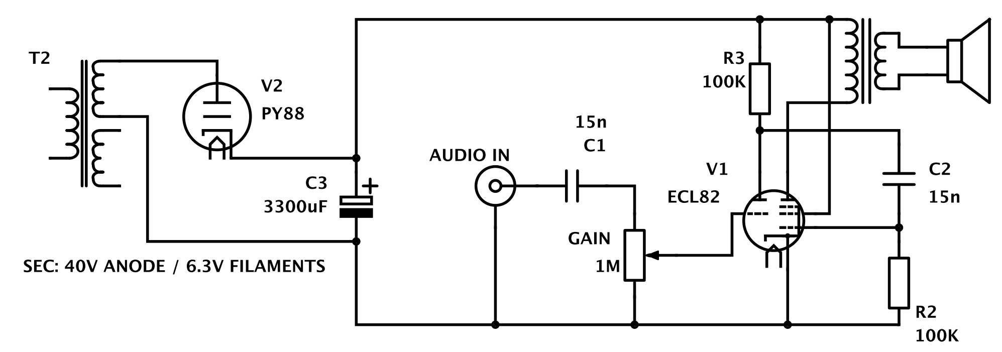 (This is not to suggest that this circuit would make a particularly good guitar amp, it will be low-wattage and might not sound great with a guitar through it, but just by way of illustration of how simple such a circuit can be- all the complexity is in the tube itself) |
|
|
|
Post by ourclarioncall on Oct 18, 2020 9:09:37 GMT -5
neweynice one newey, yes you have tuned into my brain, I’m impressed 😉 This is exactly what I’m looking for , a bare bones schematic with no frills or extras. Less clutter on the page so I can easily identify the main essential “bits” that are needed so I don’t get distracted and go down rabbit holes. Input jack, pre amp tube, volume pot, power amp tube, power transformer , output transformer , speaker. i have no intention to build anything like this as I know it won’t sound good , I just want a simple schematic that I can work through the signal path and try and get a better understanding. I read up on transformers and valves so I have a vague idea how they work. But it’s not long before I’ve forgotten what I’ve learned and have to refresh as I never learned it to the depth where it won’t be lost.
|
|
|
|
Post by newey on Oct 18, 2020 9:37:19 GMT -5
What the schematic doesn't have is a "pinout" diagram of the tube, so that you could relate which wires would connect to which pins on the tube socket. That would be a necessary step for translating the schematic to a useable wiring diagram. But that information can be easily located for the different types of tubes.
|
|


