telebob
Rookie Solder Flinger

Posts: 3
Likes: 0
|
Post by telebob on Apr 27, 2006 9:40:02 GMT -5
Hi, I new to this forum and new to the world of guitar mods. I have started a project transforming my standard Fender Telecaster into a monster. I wanted to get more sounds and I didn't want to get another guitar. I really like the way my Tele plays and feels, but I've been itchy to tear it apart and have some fun rewiring it. I'm installing entirely new guts (pots, switches, pickups, the works) and a third pickup. I wanted to see if anyone was up to the challenge of checking my proposed wiring diagram which probably has errors. You can view it at: www.captureproductionsstudios.com/bobs_tele_diagram.gif I have finished the wood work (carved out a middle pickup position and increased the control compartment by about 20%) and will be wiring it soon. I know this is a very ambitious rookie mod, but I'm confident with the help of a few more experienced guitar techs it will turn out. All advice is welcomed (ie..alternate configurations), however I'm most concerned with whether the proposed wiring diagram is accurate or possibly how to get all the same switch positions an easier way. If anyone is still reading by this point, I'm also a little concerned about ground loops with such a complicated setup. I know virtually nothing about electricity but I'm good with a solder iron and understand the mechanics of the the switches well. Any advice on how to avoid is problem, how it occurs, or if I should be worried? Thanks!!! |
|
|
|
Post by CheshireCat on Apr 27, 2006 13:19:26 GMT -5
I have started a project transforming my standard Fender Telecaster into a monster. All advice is welcomed (ie..alternate configurations), however I'm most concerned with whether the proposed wiring diagram is accurate or possibly how to get all the same switch positions an easier way. First, here's what a regular Tele control plate can look like (top and bottom) with some simple modifications and without routing too much from the top. 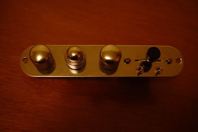 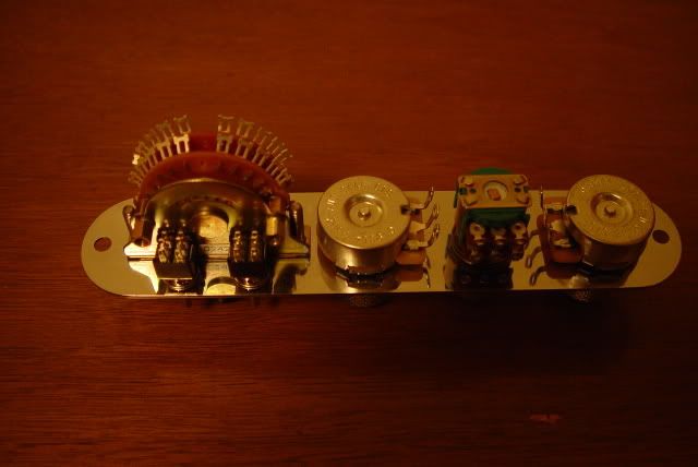 If you'll notice, that's seven controls on a regular (tho modified) tele control plate. In fact, in addition to that, what I would also suggest is backrouting, not a control cavity, but a components cavity, to be filled with whatever extra components you'll end up using, such as the black ice distortion circuit and the 0.33uf 400V isocap. (Battery box, anyone?) Now, as for your schematic, I like a lot of the ideas you're using, but I'm not sure if the series-split-parallel idea is a good one. I've never really seen the benefit to intracoil series-parallel wiring as tone options. Now, between two different pickups? It can be very dramatic. But, with the coils of a single pickup, I've never been that impressed. Someone older than I help me out here, but I'm thinking that that probably went back several decades when pickup technology was still relatively new and the fact that guitarists were looking for anything to mix it up was coupled with the fact that there wasn't much you could do with pickups at the time, being that a lot of the technology we take for granted today was still being developed. Couple that with the fact that signals were a lot cleaner back then. Basically all you had was your guitar going thru a Marshall stack or a Vox (or a Fender Bassman, which was the amp Marshalls were modelled after . . . in the days before modeling). Who knows, you might have a wah pedal perhaps, but that was it. So, in that time frame, something like Clapton's "woman tone" would work, were you had the neck humbucker pickup with the trebles rolled off (if memory serves correctly), and everything maxxed. That simple, straight-ahead, slightly affected sound would be iconic. Today, there's so much stuff in the signal chain, I'm not terribly sure that something as subtle as series/parallel within the pickup would be all that noticible. I mean, is the kid in the third row going to go "wow, I love it when he plays his middle Lil'59 in series mode rather than parallel! It just makes the whole song!" Perhaps, but I'm not terribly certain of that. Now, the SuperSwitch selections are good ones for a two pickup tele. However, that said, you have three pickups. You might consider my schematic, the UUSS. Like your schematic, it uses a SuperSwitch and a toggle, but you get these ten sounds (relative to switch being up or down): Dn: 1 N 2 N+M 3 M 4 M+B 5 B Up: 1 ALL3> 2 M>N 3 B>N 4 B>M 5 N+B If you can get your hands on an S-1 Switch, then you can do it as a push/pull (or, rather, push/push) with one of the pots. If not, a simple toggle will do it. Cost you $3. Now, another idea is that a Tele is a prime candidate for doing Jag sliders, specifically built into the pickguard on the right horn. That can handle your splitting, phase inverting, you name it. In fact, I'm setting up an active circuit that no matter what combo of pickups I have, when I flip the phase inverter on, I'll get an outtaphase sound, which may not seem that dramatic, accept for the fact that I'm mixing passive and active electronics, and you can't run EMGs backwards. Either way, if you did the UUSS method, plus a phase inverter, you'd get more sounds and combos from the same number of controls. Now, the bit with the tone controls and the black ice overdrive, neat idea. I'd like to see how that plays out. Does that help so far? Chesh |
|
|
|
Post by ChrisK on Apr 27, 2006 13:19:48 GMT -5
Blang-dang it Chesh, quit posting "my thunder" while I'm a typing! Hi telebob, welcome to the forum. Are you the same telebob that I've seen on the FDP? I don't have the time to look at your schematic now, but other's will. Consider looking at the post in the Schematics section under electronics & Wiring, you'll see the "ToggleCaster" which is probably more that humans should try to employ on a Tele, or the "TeleBlender" (a work in process) which shows some serious Tele control plate function packing. Another is the "PadoukCaster" in the Schematics Vs. Wiring Diagrams thread in Electronics & Wiring which uses the Mike Richardson schema along w/ phasing on two coils. This may well be a good schema for you, especially since you are using three pickups. You could move the phasing to the two DPDT mini-mini-toggles under the lever switch on the TeleBlender plate, and add two other SP3T (DP3T ON-ON-ON) mini-toggle switches for the splits, between the Volume and tone pots. OK Chesh, I'll post a couple of pics of what yer athinkin aboot regarding slides on the horn.....   |
|
|
|
Post by CheshireCat on Apr 27, 2006 13:44:46 GMT -5
Blang-dang it Chesh, quit posting "my thunder" while I'm a typing!  |
|
telebob
Rookie Solder Flinger
Posts: 3
Likes: 0
|
Post by telebob on Apr 27, 2006 14:25:57 GMT -5
Thanks! - CheshireCat & Chirsk
I'm not the other telebob you've seen. This is my first forum. I appreciate your ideas. I have a feeling this is the beginning of a tone quest that may be, as it has been for others, an endless one. That being said I will probably try many different wiring options.
CheshireCat- (please forgive my ignorance- like I said I'm new at this) I checked out your schematic and your leads are labeled +/- From what I have read so far I thought I understood that either lead (start or finish of the coil) could be hot or ground however the order would determine phase.
Can +/- be determined by attaching the leads of a tester (red+, black-) to the leads of a pickup and taping the pickup with a screw driver while watching for positive volt reading?
I'm not sure if this question even makes sense. I still have a lot to learn.
Thanks
|
|
|
|
Post by CheshireCat on Apr 27, 2006 15:52:03 GMT -5
CheshireCat- (please forgive my ignorance- like I said I'm new at this) I checked out your schematic and your leads are labeled +/- From what I have read so far I thought I understood that either lead (start or finish of the coil) could be hot or ground however the order would determine phase. Can +/- be determined by attaching the leads of a tester (red+, black-) to the leads of a pickup and taping the pickup with a screw driver while watching for positive volt reading? Most pickups have a "beginning" and an "end" to the coil, usually color-coded, to keep orientations consistant, so that you don't run into phasing problems. Refer back to your Duncan color codes for clarity. Most schematics on simple mods (and ALL of the Duncan schematics on their website) reference this protocol. |
|
|
|
Post by fobits on Apr 27, 2006 19:41:44 GMT -5
Hi telebob, That's a beautiful drawing, clean and clear and easy to follow. Did you do it yourself? I was waiting for some of the more experienced people to look it over. Nobody has said anything, so I'll put in my two cents. Bear in mind that I'm new at this stuff myself and I could be wrong, but..... Look at the DPDT switch on the bridge pickup. When it's in the down position, White and Red are connected together and go to output. Green and Black go to ground. The coils are in parallel, but unless I'm much mistaken, they are out-of-phase. The usual way to put Seymour Duncans in parallel is Green & White to ground, Red & Black to output. When the switch is turned up, Red and Black are joined. Green is ground and White is output. The coils are in series, but again are out of phase with one another. When the switch is in the middle position, on the right-hand side, Red and Black and Green are all grounded. That means that the output has to come from White - but on the left side White is attached to Red, which is grounded! I believe that part of the confusion is caused by the way that different companies describe the leads. Some say "North plus", "South minus", etc. Others use the "start", "finish" system. Comparing wiring diagrams from different companies, I'm pretty sure that this is how they relate: South start = South minus (Seymour Duncan green) South finish = South plus (Seymour Duncan red) North finish = North minus (Seymour Duncan white) North start = North plus (Seymour Duncan black) In your diagram the North leads are labeled the opposite way, which would explain why they're out of phase. Now somebody will explain that I don't know what I'm talking about, which is probably correct  |
|
|
|
Post by Mike Richardson on Apr 27, 2006 20:19:58 GMT -5
Being the owner of a Black Ice unit, I can say that I personally find it absolutely useless. It works best with high-output pickups. Well, duh! That makes it totally redundant. If you put one on a Strat, you hardly notice it's there. If your guitar has, say, a Super Distortion, you don't need the Black Ice at all. Now that I've gotten that little rant out of the way--If I were wiring that guitar (and I'm not!), I would set the Super Switch up so that the switching order is more logical: Bridge, B/N in series, B/N parallel, B/N series, out of phase, Neck. Now that I've gotten THAT little rant out of the way  , I'll say it looks like a cool project! Good luck with it. PLEASE make sure it's well-shielded!! |
|
|
|
Post by CheshireCat on Apr 27, 2006 21:41:56 GMT -5
Being the owner of a Black Ice unit, I can say that I personally find it absolutely useless. It works best with high-output pickups. Well, duh! That makes it totally redundant. If you put one on a Strat, you hardly notice it's there. If your guitar has, say, a Super Distortion, you don't need the Black Ice at all. An Artec QDD2 would work nicely instead. Besides, you need a battery box in there. It just feels naked without one. |
|
|
|
Post by sumgai on Apr 28, 2006 2:15:01 GMT -5
telebob, Hi, and  to the forums. Looks like you're gonna be around for awhile, the spell of GMS is upon you! I took a look at your diagram, and I now see why The Unkster doesn't like to read non-schematic drawings. I'm all better now, but for a moment there, it was touch and go until I could get the Excedrin down!  That thing is..... err... intricate, yeah, that's what it is. Oh boy. Frank doped out the HB switching stuff just fine, leaving me to point out that you don't need to ground the neck's negative lead in the first position. (You label it as neck-start.) Other than that, I'd sure like to be on whatever you were having while drawing this up, because it's gotta be good stuff!  And for the record, I concur with Mike, it would make much more sense ergonimically to re-arrange the switch positions to what he said. Unless you were going for the "fool the geeks in the audience" look - "Hey, he's in the neck position, but I clearly hear the bridge pup!!"  The clamor over labeling pup leads will never die down, due to no standards. (Implying that such would have to be set by a government body.) But convention has it that we don't worry about 'start' or 'finish', instead we call the leads 'plus' and 'minus' (or their respecitve signs, + and -), or 'hot' and 'negative', or similar terms. This comes about because we literally can't delve into a pup and determine the direction in which it is wound. And without a clear directive from each pup maker, such as: "We wound this coil CW as viewd from the top", we modders are on our own. It makes no sense to rely on what we can't dope out for ourselves, so we just use color codes, and hope for the best.  (But it's a simple matter to go back in and reverse one of the pup's leads, if necessary.) HTH! sumgai |
|
|
|
Post by simes on Apr 28, 2006 10:10:17 GMT -5
Now, as for your schematic, I like a lot of the ideas you're using, but I'm not sure if the series-split-parallel idea is a good one. I've never really seen the benefit to intracoil series-parallel wiring as tone options. Now, between two different pickups? It can be very dramatic. But, with the coils of a single pickup, I've never been that impressed. I have a normal-sized bridge HB wired for series-parallel switching (I assume that's what you're referring to, Chesh - wouldn't that be "intercoil" rather than "intracoil"?), and the difference is certainly quite dramatic, in the sense that I can get a very reasonable SC imitation out of it in parallel mode. Plus, it's still humcancelling. I would be interested, though to know just how convincingly SC-ish a narrow HB like the Li'l '59 would be when wired in parallel. |
|
|
|
Post by Mike Richardson on Apr 28, 2006 14:49:36 GMT -5
I have tried most of Duncan's Strat-size humbuckers. Running the Little '59 in parallel won't sound exactly like a single-coil, but it shouldn't be far off. I have a Cool Rails in the bridge of one of my guitars, and in parallel it's fairly close. The Little '59 is very similar, with a little more bite on top. It should be okay. The one thing you should probably never do with most of these pickups is use them as a single coils. They sound AWFUL, like an icepick in the forehead. The one exception, in my experience, is the Hot Rails, which can work okay as a single, but it still isn't great. The Vintage Rails and Duckbuckers, which had two conductor wiring, were wired in parallel always. The newer versions have four conductors, so you can get a fatter tone out of them, too.
|
|
telebob
Rookie Solder Flinger
Posts: 3
Likes: 0
|
Post by telebob on May 5, 2006 13:57:41 GMT -5
Thanks to everyone for all the advice. Sorry I've been absent (still recovering from solder burns). If anyone is still listening I've finished (for now) my little science experiment and after some reworking (and rewiring) it sounds very cool.
fobits-
I did do the drawing myself (professionally I'm a Graphic Designer) and I'll post the revised edition when I get a chance. I'm glad you like it. You're correct about the phase of the humbucker- I got a bad color code somewhere online. Unfortunately (or fortunately, it is after all a learning process) I found this out after it was all wired up. It only took me a total of 3 tries at a few hours a piece to get the phase relationships that I wanted.
As far as the single coil middle toggle switch positions- correct, one coil is grounded out (both+,- going to ground). The middle HB rear coil is active when it's toggle is in middle position and the front coil is active on the bridge HB when it's toggle is in middle position.
CheshireCat-
In reference to the Series/Parrellel of a HB and a sc-sized HB- to my ears I get three distinct sounds from the mini toggle wired to each Lil '59 (Series/Coil Cut/Parrellel). The coil cut and parrellel are similar but different and there is a considerable difference between the series and parrellel. With series I get a traditional big fat HB sound. I almost forgot- I've got a late 60's (probably 1969) Fender Bassman 100 that sounds awesome!! Unfortunately I don't have a cab for it right now. Any recommendations?
Mike-
I'm actually pleased with the black ice. Not at first because of the phase relationship errors that I had (no position was hot enough to push the black ice to clip) and it isn't useful in every position for the same reason. With the black ice disengaged and a hot position selected, such as the bridge in series, I get a big sound but it is still a fairly clean sound. The same position with the tone knob up and the pot now dailing in the black ice distortion level, I can get anywhere from a warm blues overdrive to a real fuzzed out tone. Its probably not great for metal but it will be fun for me. It is actually more drive than I anticipated from a passive control- no battery needed! One thing that might be problematic is because it is clipping the signal it actually attenuates the level. No problem if you're not wanting to hit it on the fly. Oh yeah- I agree- I shielded everything.
sumgai-
The switching order makes sense to me. The first three are standard tele functions-this is what I'm used to. The next two are "extras" N/B series & N/B series out of phase.
Each HB has a S/cc/P toggle, the master volume pot push/pulls my middle p/u to add it to any switch position. Lastly, the tone control doubles as an overdrive when pulled (although it defeats my tone control, its worth it to have onboard overdrive. I find myself playing with the tone dailed in @ 10 alot anyway).
--Not exactly simple but lots of tone possibilities and lots of fun.
WHEW- Thats alot! Thanks again everyone! I'll post pics soon.
|
|


 , I'll say it looks like a cool project! Good luck with it. PLEASE make sure it's well-shielded!!


 (But it's a simple matter to go back in and reverse one of the pup's leads, if necessary.)