|
|
Post by antigua on Mar 7, 2021 4:26:07 GMT -5
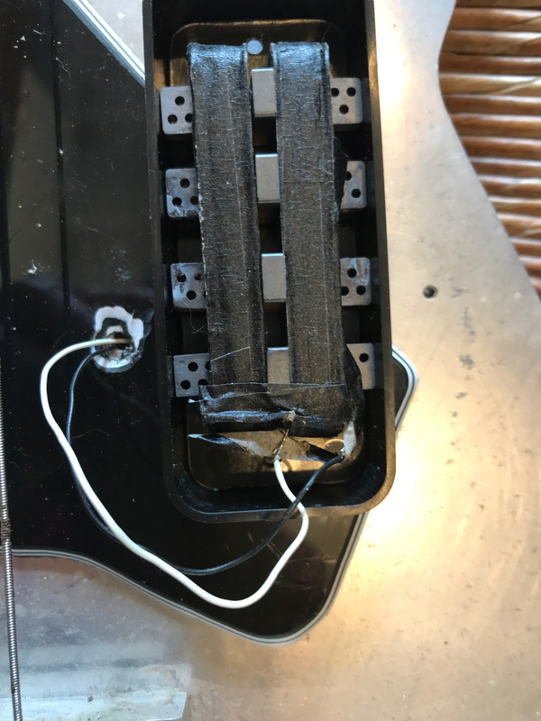
 I bought and installed this 1.5mm thick decorative aluminum pickguard a few years ago, prior to doing testing that showed how effectively such things cause eddy currents and burn off treble response, and I've known ever since then how bad this probably is, but I've kept it as it is because I love the metal engraving. But I was finally curious enough to test it out with the oscilloscope and integrator to see what what the situation is. I've tested it with and without the nickel silver cover on the pickup, as well as with a slotted cover, the sort described by Ken Willmott's Tele neck cover cutting blog post, but I have to mention that the slotted cut neck cover is brass, not nickel silver. I'm making a slotted cut nickel silver cover now, and I'll post a follow up when it's done. Long story short, the aluminum pickguard isn't that bad by itself, and it's not nearly as bad as the pickup cover, which is nickel silver. The aluminum pickguard brought the resonant amplitude down 6dB, where as the cover brought it down by 20dB. So in conclusion, it's not as good as a plastic pick guard, but not as bad as a cover, which is about what I had expected, and why I've left it this way for a long time. But the combination of the aluminum pickguard and the nickel silver cover (which it should be mentioned is chrome plated, which includes a layer of copper) makes for an overall heavy attenuation. But I really want to have a metal cover on this pickup, I think think it looks better that way, so I decided to try out the slotted cover, with the cuts that disrupt the eddy currents, and that worked out pretty good; the aluminum pickguard + slotted cover shows less attenuation that the covered pickup alone, so it looks like if I combine the aluminum pickguard and a slotted cover, I can have my cake and eat it too.  As a side topic, it would be interesting to measure the eddy currents of a chrome plated nickel silver cover, and then sand off the chrome, down to the nickel silver, and measure it again, to see how much of an improvement is made in the Q factor. A lot of the variation from one nickel silver cover to another might have to do with differences in the chrome plating.  This is the slotted cover, I'm using it as a guide to cut a second slotted cover, being nickel silver instead of brass. I like this cut design because it hides the cuts under the strings. I was using a jewelers saw, but it was too squierly so I ordered a stiff razor saw, and I'm going to wait until it arrives before continuing.  |
|
|
|
Post by stratotarts on Mar 7, 2021 10:19:21 GMT -5
Cool and interesting. I wondered about the aluminum pickguard on my Squire Jazzmaster, no time to look into that yet. I can't see the whole process for your slot cutting, but it appears that you are using the humbucker slot configuration, that's not quite right for the single coil. Although the slots across the top probably do provide some improvement, the really effective cuts have to extend from the center line across the poles, longitudinally across (so half of the slots that you have cut there) and completely down one side. If the sides are not cut, the sides of the cover become an active circuit.
Secondly, it might be a sacrilege with such a nicely decorated pickguard, but you could also slot it with a small cut between the pickup and the neck, right in front of the truss rod adjustment screw.
|
|
|
|
Post by antigua on Mar 7, 2021 13:20:43 GMT -5
Cool and interesting. I wondered about the aluminum pickguard on my Squire Jazzmaster, no time to look into that yet. I can't see the whole process for your slot cutting, but it appears that you are using the humbucker slot configuration, that's not quite right for the single coil. Although the slots across the top probably do provide some improvement, the really effective cuts have to extend from the center line across the poles, longitudinally across (so half of the slots that you have cut there) and completely down one side. If the sides are not cut, the sides of the cover become an active circuit.
Secondly, it might be a sacrilege with such a nicely decorated pickguard, but you could also slot it with a small cut between the pickup and the neck, right in front of the truss rod adjustment screw.
I ordered this www.amazon.com/gp/product/B000BRBZYC/ref=ppx_yo_dt_b_asin_title_o01_s00?ie=UTF8&psc=1 , only $20 and it looks perfect for the task, but there are a lot of reasons it might fail, such as the teeth being too coarse or too thin, but it says it can cut soft metal so I'm optimistic. That's a good idea about cutting the pick guard, I'd probably put the cut under the low E, and patch it with black or gray filler. I'll wait for the straight saws to show up because I can't get straight cuts with the jig saw / jewelers saw. You cant see it but the cut cover has one cut extending to the bottom of the cover. Even if this cut pattern isnt the most optimum, I think it looks the best and it's the easiest to produce since the cuts are all straight across. |
|
|
|
Post by JohnH on Mar 7, 2021 16:18:07 GMT -5
I love that pick guard!
Not to derail too much, but I have been finding out things about eddy current effects in aluminium, at the other end of the signal chain.
I have some designs on the Marshall forum for reactive attenuators where an air-core inductor is used to give it a varrying impedance to match that of a speaker. These units are usually mounted in a thick aluminium case. So the inductor coil often has one face close to or touching the case. The eddy currents induced seem to oppose the flow in the coil, shifting the phase a little and reducing the inductance by a few %. At the same time, since energy is being dissipated, I'm assuming the phase shift is also adding to resistance at high frequency (ie the 'real' part of the impedance). Not wanted!
The effect is mostly avoided if the coil is offset from the case by a few mm.
The overall result gets further mixed up if a steel bolt is used to mount the coil. This can easily add 50% to a carefully calculated coil inductance.
I reckon the same physics is in play with pickups too, in relation to various metallic items around them.
|
|
|
|
Post by antigua on Mar 7, 2021 23:49:29 GMT -5
I love that pick guard! Not to derail too much, but I have been finding out things about eddy current effects in aluminium, at the other end of the signal chain. I have some designs on the Marshall forum for reactive attenuators where an air-core inductor is used to give it a varrying impedance to match that of a speaker. These units are usually mounted in a thick aluminium case. So the inductor coil often has one face close to or touching the case. The eddy currents induced seem to oppose the flow in the coil, shifting the phase a little and reducing the inductance by a few %. At the same time, since energy is being dissipated, I'm assuming the phase shift is also adding to resistance at high frequency (ie the 'real' part of the impedance). Not wanted! The effect is mostly avoided if the coil is offset from the case by a few mm. The overall result gets further mixed up if a steel bolt is used to mount the coil. This can easily add 50% to a carefully calculated coil inductance. I reckon the same physics is in play with pickups too, in relation to various metallic items around them. Could the case in question be cut across the magnetic axis, and then re-secured using something non conductive? |
|
|
|
Post by JohnH on Mar 8, 2021 2:03:28 GMT -5
Could the case in question be cut across the magnetic axis, and then re-secured using something non conductive? I wondered about making a feature, with the coil at the centre and slots radiating out like the rays of the sun! But having understood the issue, there are easier ways to control it. |
|
|
|
Post by ms on Mar 9, 2021 5:46:44 GMT -5
I have some designs on the Marshall forum for reactive attenuators where an air-core inductor is used to give it a varrying impedance to match that of a speaker. If you want to match the impedance of the speaker perfectly, you need some eddy current loss in your coil since the speaker coil has some such loss. The amount presumably depends on magnet material, etc. Probably not a big deal, but maybe there is no need to try to eliminate the accidental eddy currents. |
|
|
|
Post by JohnH on Mar 9, 2021 13:33:43 GMT -5
I have some designs on the Marshall forum for reactive attenuators where an air-core inductor is used to give it a varrying impedance to match that of a speaker. If you want to match the impedance of the speaker perfectly, you need some eddy current loss in your coil since the speaker coil has some such loss. The amount presumably depends on magnet material, etc. Probably not a big deal, but maybe there is no need to try to eliminate the accidental eddy currents. Thats true enough. Its not a huge issue, just a slight curved ball in the design process. the key effect that needs to be captured is that speakers have a rise in impedance with frequency, and I work with measured traces from a real 4x12 cab. You can match that very closely using SPICE in the range up to about 5khz with a series resistor, an inductor (including its own dcr), and a bypass resistor in parallel with the inductor. This lets me home in on the component values. But with these effects of proximity to other metals, it becomes harder to assess what the best values to specify should be, so short of much better tests, its best to minimise the effects in order to keep control. |
|
|
|
Post by antigua on Mar 10, 2021 0:59:58 GMT -5
Follow up on the nickel silver slot cut cover; the cut nickel silver cover did not show lower attenuation than the cut brass, so my conclusion is that there's no need to waste the money on nickel silver covers if the intention is to cut it up.
|
|
|
|
Post by antigua on Mar 10, 2021 3:10:12 GMT -5
I completed cutting both a new cover as well as a thin cut in the aluminum pick guard. The saw is .008" thick, so the cuts in the pick guard is nearly invisible, I didn't have to fill gap. The cuts in the cover are more obvious when the strings are removed, because the chrome is highly reflective and it hides nothing as compared to the dull aluminum. But once the strings are on, you can't really tell if you're seeing the cuts or reflections of the guitar strings, so they become effectively invisible. The D string cut extend all the way to the bottom of the neck side of the cover. Since the cover crimps to the pickup on both sides, that was the most stable place to have the cover be fully cut. We never did test cutting a Tele bridge in order to reduce eddy currents around the bridge pickup, but based on this result with the pick guard, it's reasonable to expect the eddy currents would be eliminated completely.  This post-op bode plot shows that the cut aluminum pick guard causes near 0% attenuation, as it has no conductivity around the perimeter, but the cut cover still attenuates somewhat, the drop in amplitude is only 4dB, compared to the 20dB drop at resonance beforehand.  |
|
|
|
Post by antigua on Mar 11, 2021 14:44:49 GMT -5
\ I put a cut into the Tele bridge, but that turned out to not be a great idea; the resonant amplitude only increased by 2dB without load, so with load, there would be no increase to speak of. But worse, this base plate is stamped steel, so I didn't realize there was tension in the structure that was released with the cut was made, and you can see how it torqued when cut:  Even if I bent it back into place, it want to adjust and isn't rigid. So as a quick fix I used super glue and mending plastic on the underside of the bridge plate. Then mending plastic preserves the break in the continuity, but overall it wasn't worthwhile to make this modification. The cut is virtually invisible now, since the saw blade used is only .008" If the bridge was sintered steel instead of pressed steel, it probably would have worked out better as well as have had a bigger impact on the Q factor.  |
|
|
|
Post by frets on Mar 11, 2021 15:57:16 GMT -5
Hey Antigua,
I’m so sorry you had that break, but your repair is exemplary. 👏🏾
|
|
|
|
Post by ms on Mar 17, 2021 11:15:28 GMT -5
|
|
|
|
Post by antigua on Mar 17, 2021 14:46:45 GMT -5
I've always wondered what an aluminum neck would feel like. I've only seen pictures of such things.
The Lace Alumitone has heavy eddy current attenuation also, although it's also a humbucker layout, and I'm not 100% sure what the situation is when you have coils with currents that are 180 degrees offset, as in a humbucker.
|
|
|
|
Post by blademaster2 on Mar 17, 2021 21:31:05 GMT -5
Very interesting. Is it possible that the difference between these cases, in db, would become a lot less when plugged in? I would like to see the same plots done when you have a cable loading the guitar signal. (I presume that the 'brown' plot is with the Ni/Ag cover but no Al guard, but was labelled as BLACK in error?) |
|
|
|
Post by antigua on Mar 18, 2021 10:24:23 GMT -5
Very interesting. Is it possible that the difference between these cases, in db, would become a lot less when plugged in? I would like to see the same plots done when you have a cable loading the guitar signal. (I presume that the 'brown' plot is with the Ni/Ag cover but no Al guard, but was labelled as BLACK in error?) The Q factor drops to some extent, depending on the resistance value of the of the control pots. The 200k dummy load its somewhere between 250k vol tone and 500k vol tone. The plot above is only realized if 1 meg pots, or no pots are used. Typically the eddy current attenuation of a brass covered Tele neck is so high that even with 1 meg pots the amplitude at resonances is still low that the amplitude at 1kHz. Here's an older plot from cut cover testing with a dummy load, the lowest black line is a brass cover with no dummy load.  this is the cover plotted above  |
|
ghobii
Rookie Solder Flinger

Posts: 2
Likes: 0
|
Post by ghobii on Apr 24, 2021 19:38:37 GMT -5
Do you think an aluminum pickup ring would have the same effect as that pickguard? I would think just the metal close to the pickup would interact with it, or does the size/mass come into play?
|
|
|
|
Post by antigua on Apr 24, 2021 22:48:15 GMT -5
Do you think an aluminum pickup ring would have the same effect as that pickguard? I would think just the metal close to the pickup would interact with it, or does the size/mass come into play? I wondered about this too, because I have Zemaitis guitars with aluminum mounting rings. Thickness plays into it, the thicker the metal, the greater the intersection between metal and lines of flux, and the lower the resistance through the material. The degree of eddy current intersection has to do with where lines of flux are most concentrated. Most eddy currents comes from conductive metal in the core of the coil. Second most comes from metal directly outside of the core, top and or bottom. Third would be the outside of the coil. And that's just with respect to the coil, there are also eddy current attenuations with respect to the guitar strings, so metal that is between the string and the pickup causes much greater attenuation than metal that is anywhere else. For that reason, the eddy currents caused by the steel plate on the bottom of a Tele bridge pickup are not nearly as extreme and problematic as the eddy currents caused by the cover that is over the Tele neck pickup, even though the Tele neck pickup's cover is thinner and often a less conducive nickel silver alloy. A pick guard or metal mounting ring intersects with the return path of the magnetic field, the part that is on the outside, and it would seem like the intersection is substantial, but testing shows that the eddy current action with the aluminum pick guard and the Tele bridge plate is very small, around 1dBV in a circuit that is already loaded down with a tone and volume pot. The attenuation is more substantial with no load, no volume or tone pot, but almost nobody ever wires a pickup straight to the output jack of the guitar, and that higher Q factor wouldn't make for a good sound anyway. The reason why the effect is not substantial is probably a combination of the metal not being real close to the guitar strings, and the flux density being lower there. If you wanted to take a measure against eddy current losses due to metal parts around the pickups, you could install 1 meg tone and volume pots. |
|
ghobii
Rookie Solder Flinger
Posts: 2
Likes: 0
|
Post by ghobii on Apr 25, 2021 10:18:10 GMT -5
Thanks for the reply! I just started making pickups and am slowly wading through the vast amount of info here, learning how all the different components interact with each other. I have a CNC router and am building my own design guitar, and decided why not go all in and make the pickups too. And I figure since I'm making everything, I can really experiment with non-standard pickup shapes and sizes if I want.
The question came up because I've been making aluminum pickup rings for my guitars and was wondering how much they might be effecting the sound. I didn't get the impression I was losing any significant top end, but hadn't done any real A_B testing yet.
|
|
|
|
Post by antigua on Apr 25, 2021 17:42:38 GMT -5
Thanks for the reply! I just started making pickups and am slowly wading through the vast amount of info here, learning how all the different components interact with each other. I have a CNC router and am building my own design guitar, and decided why not go all in and make the pickups too. And I figure since I'm making everything, I can really experiment with non-standard pickup shapes and sizes if I want.
The question came up because I've been making aluminum pickup rings for my guitars and was wondering how much they might be effecting the sound. I didn't get the impression I was losing any significant top end, but hadn't done any real A_B testing yet.
For the most part, if you have excess eddy currents you can just use 500k or 1 meg pots to reduce treble loss, but if there's a high degree of conductive parts, it will be dark regardless. A Filter'tron has a big attenuation, because of the larger filister screws in the core, but the use a low inductance of less than 2 henries, so the resonant peak is very high, and they have decent treble response despite the steep roll off. |
|