|
|
Post by frets on Aug 13, 2021 15:55:47 GMT -5
Happy Friday Guys!! As you all know, I attempt some aggressive wirings (except for the last one). And I’ll admit that my weakness is blade switches. I just can’t modify a switch to save my life. Anyway, I’m looking at the diagram below for an HH and want to modify it for an HSH using a 5-Way. Standard B, B+M, M, M+N, N wiring would be the aim. However, translating this from the 3 way to the 5-Way, I know not how to do (Yoda!). If it is possible, can one of you throw me a bone? I don’t even know where to start so that the Series and Phase work with the 5-Way config that includes the single coil middle pup. As always, Thanks!  |
|
|
|
Post by unreg on Aug 13, 2021 17:47:35 GMT -5
Happy Friday! 🙂
Since we’re in the coffee shop, I prefer milk and cane sugar.
EDIT: Obviously, I don’t expect anyone to serve me… just talking about my coffee. 🙂👍
|
|
|
|
Post by Yogi B on Aug 13, 2021 19:07:06 GMT -5
Lucky Friday the 13 th everybody! I presume you're talking about a standard Strat 5-way, not a superswitch/megaswitch. A superswitch is more likely to make things that I'd want to do, possible — such as swapping the HB coil splits when out of phase (for hum-cancellation purposes). A superswitch/megaswitch could also make it possible to order the series mode positions in a logical fashion. (Not exactly what you're after, but I have a scheme using a megaswitch that gives {B, B+M, M, M+N, N} then via toggling a DPDT gives {B×M, B×-M, B+N, N×-M, N×M}, note that's bridge & neck in parallel in the middle position.) Nevertheless, I'll see what I can come up with with a standard 5-way. In any event it's probably better starting a wiring diagram from scratch anyway: as you've discovered from your other recent thread, not many supposedly reputable sources of wiring diagrams know how to correctly wire a series-parallel switch in combination with a three-way switch.
|
|
|
|
Post by newey on Aug 13, 2021 21:52:35 GMT -5
not many supposedly reputable sources of wiring diagrams know how to correctly wire a series-parallel switch in combination with a three-way switch.  "supposedly reputable" gave me a laugh. According to . . .them? EDIT:and, I take unreg's point that this thread would probably be better suited to Guitar Wiring. It would be more visible there, anyway. But since the Coffee Shop is sort of the catch-all area, I can't recall ever moving a thread out of the Coffee Shop. So here it shall remain, unless frets asks me to move it. |
|
|
|
Post by reTrEaD on Aug 14, 2021 7:01:37 GMT -5
Nevertheless, I'll see what I can come up with with a standard 5-way. A few years ago, I looked at doing something with three-pickups, based on this two-pickup strategy: 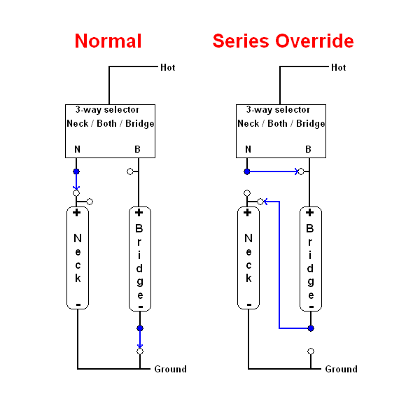 Problems arise when using 3 pickups and a standard 5-way. Which pickup do you want to 'tuck under' the other two when in series mode, and to which lug of the 5-way do you want to connect the lug that now has the pickup missing from its connection? For instance, if we put the Middle pickup in series with whatever else we might select, we would need to connect the M lug of the 5-way to either the N or B lug when in series mode. If we choose B, we get the following: 5 - Neck x Middle 4 - (Neck + Bridge) x Middle 3 - Bridge x Middle 2 - Bridge x Middle 1 - Bridge x Middle And if we use the other side of the 5-way to auto-split the HBs in the 2 and 4 positions, and continue to choose B as the connection for the missing middle pickup, we get: 5 - Neck HB x Middle 4 - (Neck split + Bridge HB) x Middle 3 - Bridge HB x Middle 2 - Bridge split x Middle 1 - Bridge HB x Middle
Of course, there are several other options regarding which pickup goes in series and which lug to connect to, to manage the missing pickup. But the auto-split doesn't fit nicely when one of the HBs is 'tucked under' whatever else we might select. |
|
|
|
Post by frets on Aug 14, 2021 11:26:12 GMT -5
I’m going to do it on a Superswitch. I’m redoing the whole diagram, it’s just got me confused (easy to do!!😸). I think there is a way to do it. But it will require a Superswitch. I think I see it!! Come to me oh diagram!!  |
|
|
|
Post by Yogi B on Aug 14, 2021 20:30:23 GMT -5
For instance, if we put the Middle pickup in series with whatever else we might select, we would need to connect the M lug of the 5-way to either the N or B lug when in series mode. Ideally we'd want to connect something, but leaving it open would give: | 1 | 2 | 3 | 4 | 5 |
|---|
| B × M | B × M | Open | N × M | N × M |
Or with the auto splits: | 1 | 2 | 3 | 4 | 5 |
|---|
| B × M | B split × M | Open | N split × M | N × M |
which I think I'd prefer even with the dead position. Alternatively, leaving the middle pickup connected to the centre lug, thus letting the other pickups be shorted in positions 2 & 4 gives: Or if the auto splits are left in place: | 1 | 2 | 3 | 4 | 5 |
|---|
| B × M | B POoP + M | M | N POoP + M | N × M |
frets, the scheme I currently have in mind for a superswitch would give: | 1 | 2 | 3 | 4 | 5 |
|---|
| Parallel | B | B + M | M | N + M | N |
|---|
| Series | B | B × M | M | N × M | N |
|---|
Where, as previously mentioned, the phase switch would double as a coil select for the coil split — ensuring hum-cancellation in positions 2 & 4 when split, and allowing selection of either of the HB coils in positions 1 & 5. It'll take a little while for me to draw a diagram, but in the meantime here's a text based version for critique: Superswitch | Common | Throw 1 | Throw 2 | Throw 3 | Throw 4 | Throw 5 |
|---|
| M+ | | link M | output | link M | | | phase + | B+ | B+ | | N+ | N+ | | phase − | B− | B− | | N− | N− | | ground | link S | | *** | | link S |
S1: Series-Parallel Switch | Throw 1 | Common | Throw 2 |
|---|
| output | link M | | | ground | link S | link M |
S2: Phase Switch | Throw 1 | Common | Throw 2 |
|---|
| output | phase + | link S | | link S | phase − | output |
S3: Coil Split Switch | Throw 1 | Common | Throw 2 |
|---|
| B tap | link S | | N tap | link S |
For the push/pulls "Throw 1" is the down position; "output" in reality refers to the input of the master volume; "M−" is not listed above as it's permanently grounded; the neck tone pot is connected between "N+" & "N−", and likewise for the bridge tone pot. *** Edit: While drawing this up (not done yet, but soon...), I realised it might make sense to add a resistor in position 3 to tame the middle single coil, so I've swapped around the last pole of the superswitch — thus an optional resistor can be connected between the 3 rd throw & the volume pot input. |
|
|
|
Post by frets on Aug 15, 2021 19:33:19 GMT -5
Yogi😻,
I do so appreciate you working this out. The configuration looks great. I can’t thank you enough for doing a drawing of it. You’re the best!
|
|
|
|
Post by Yogi B on Aug 16, 2021 2:17:02 GMT -5
Here you go frets. This diagram uses SD colours for the humbuckers, and assumes the middle single coil is south polarity thus the HBs are splits to their north (slug) coils when in phase. |
|
|
|
Post by newey on Aug 16, 2021 5:20:44 GMT -5
Nice work, Yogi B. I haven't checked it all just yet but so far I see no issues with it. |
|
|
|
Post by frets on Aug 16, 2021 13:07:01 GMT -5
Yogi😻,
I can’t thank you enough for this diagram. You are an Archangel!! I plan on building it in the next couple of days and will report back. I am going to do the optional resistor. Your diagrams are the “most” on Guitarnutz. Thank you thank you thank you.
|
|
|
|
Post by unreg on Aug 16, 2021 15:32:42 GMT -5
Yogi B, your vertical jack is correct! 👍 This diagram is extreme! I have a question: why did you draw a wire from the output jack’s sleeve connection to ground? Isn’t the cable’s sleeve the source of ground that everything all ground wires are is supposed to connect to? I'm guessing that ground wire just represents the cable plugged in, but I’m usually wrong. Please help my understanding of this tiny aspect of your massive diagram sir. 🙂 EDIT: or maybe that is just a kind way of showing the source of ground?
|
|
|
|
Post by Yogi B on Aug 16, 2021 17:36:10 GMT -5
Yogi B, your vertical jack is correct! 👍 And it is vertical because it's horizontal I usually get wrong. Though you have reminded me that I haven't (until now, that is) added "T" & "S" labels onto the shape. Speaking of labels is it just me, or have I labelled the lugs on the push-pulls' DPDT switch upside down? Their primary reason for existing is simply for reference, so it doesn't really make much difference, but I'd usually expect the lower numbers to be connected when the switch is down. Looking at a Bourns data sheet they agree that I've got it wrong, though CTS push-pulls disagree. I should probably draw the chassis ground symbol, because as you point out 'proper' (earth) ground should be provided from the amp via the cable. However few diagrams use the chassis ground symbol, so potentially a lot of people would have questions as to what the weird italicised "M" was. But why am I including a symbol at all? My intention is that I'm communicating: anything else that I've omitted (such as the wire from the bridge/trem-claw, or if the single coil had a baseplate) which ought to be grounded should (perhaps indirectly) connect to this point. |
|
|
|
Post by newey on Aug 16, 2021 19:22:26 GMT -5
have I labelled the lugs on the push-pulls' DPDT switch upside down? Their primary reason for existing is simply for reference, so it doesn't really make much difference, but I'd usually expect the lower numbers to be connected when the switch is down. Looking at a Bourns data sheet they agree that I've got it wrong, though CTS push-pulls disagree. I don't doubt that the numbering varies, I'm unaware that there is any standardization. I'va also seen the commons called "A" and "B", and the upper and lower lugs numbered 1-2, 3-4. |
|
|
|
Post by frets on Aug 25, 2021 14:50:13 GMT -5
Hi Yogi🥰, I wanted to let you know that the HSH diagram you did for me works perfectly. 😸😸😸 You can re-post it as verified. I just finished building and testing the first of two I’m building. I went ahead and used silicone wire to keep it cleaner. I plan on making them Solderless but here is the first. Not too much of a jungle!! I went with .022 on the Bridge and .015 on the Neck. The resistor with the Middle pup sounds awesome. I went with a 180k.  Thank you again for doing this for me. Hopefully others will use the diagram in the future. It is extremely powerful. |
|


