|
|
Post by gckelloch on Oct 26, 2021 20:07:18 GMT -5
Looks good. You asked if there was anything else you might need. I am very pleased with this wiring kit: www.amazon.com/dp/B07T4SYVYG?psc=1&ref=ppx_yo2_dt_b_product_detailsThe Silicon insulation doesn't melt easily and the kit has some useful extras. You could go for the 24AWG kit if you want more room for wire and to fit more wires into connection holes or whatever. It doesn't make any difference in sound (DCR is still much too low to matter), but is just slightly more delicate to work with. |
|
|
|
Post by thedirestrat on Oct 26, 2021 22:46:36 GMT -5
Thank you so much! I'll definitely order some of this. I already have some cloth push back wire, so I'll be using that first.
Also, I remembering seeing in a video someone connected all the pots with busbar wire, and then grounded the volume pot (obviously). Is that a smart idea? I mean busbar has no insulation.
|
|
|
|
Post by gckelloch on Oct 26, 2021 23:00:01 GMT -5
Using bare wire for grounding might make it easier to see which wires are used for grounding, but there's no other reasoning behind it I know of. Push wire may be a tad easier to solder because the insulation may spring back over connections, but I don't think it really matters, and it is a bit bulky. Same thing with large high V caps. They don't sound any better in guitar circuitry. Ceramics can fall apart though. Best to use something else if you can. Others may know more about all this, and some will surely speculate.
|
|
|
|
Post by newey on Oct 27, 2021 4:57:27 GMT -5
I've never seen the point of using cloth-covered wire unless one is repairing a vintage axe where it is desireable to be "period correct". Of course, if you have it already, no reason not to use it.
If one is shielding the cavity, using bare wire for any connections runs the risk of shorting to the shielding once all the wiring gets stuffed into the cavity and everything is buttoned down. I avoid it for that reason.
|
|
|
|
Post by thedirestrat on Oct 27, 2021 11:28:04 GMT -5
I've never seen the point of using cloth-covered wire unless one is repairing a vintage axe where it is desireable to be "period correct". Of course, if you have it already, no reason not to use it. If one is shielding the cavity, using bare wire for any connections runs the risk of shorting to the shielding once all the wiring gets stuffed into the cavity and everything is buttoned down. I avoid it for that reason. That’s what I thought too! Perfect I’ll use insulated wire then for that. |
|
|
|
Post by thedirestrat on Nov 2, 2021 21:10:56 GMT -5
 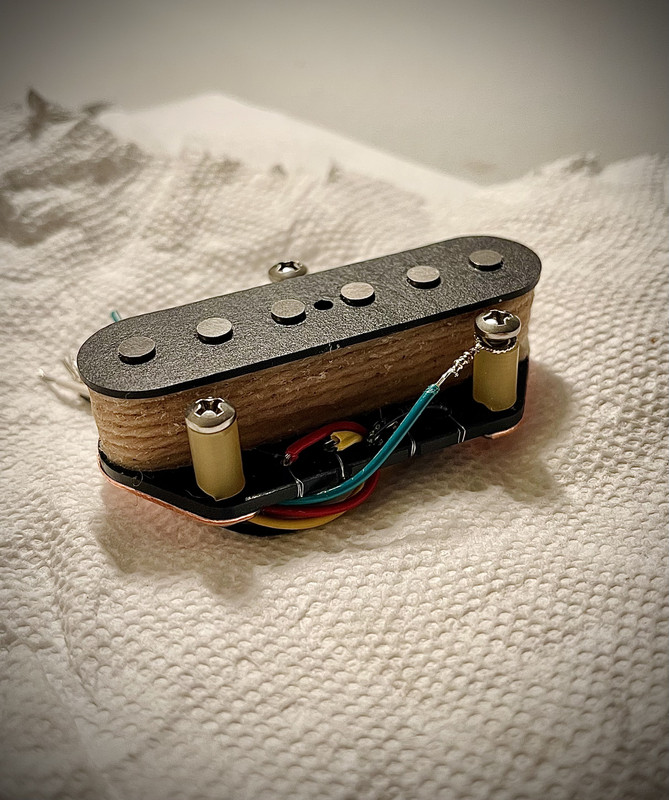 They have arrived. My life is no longer the same. Enough with the dramatics, here are the specs! I tested some stuff out with my LCR meter. Let's start with the bridge pickup: Low ("Bakersfield" as called on Yogi's schematic) Tap:
Resistance: 7.69 KOhms Inductance: 2.43 Henries Broadcaster:Resistance: 10.41 KOhms Inductance: 4.32 Henries ("Humongous") Tap:Resistance: a whopping 14.05 KOhms  ) Inductance: 7.69 Henries These values "make sense". In theory, they seem to hold properties I desire for this project! Off to a great start  Now the Neck Pickup: (Fat) 8500 Turns (Black/Start + White/Finish):
Resistance: 8.17 KOhms Inductance: 2.46 Henries (Low) 2000 Turns (Yellow/Start + Red/Finish):
Resistance: 2.48 KOhms Inductance: 0.25 Henries Total Resistance: 2.48 KOhms + 8.17 KOhms (these taps are going to be in series, and we know that resistors' (the windings act as a resistor) values add up in series) = 10.65 KOhms Pretty. Darn. Cool. Last thing that I tried to measure was capacitance. Here the values were very strange. I don't think I'm doing this right. For the bridge pickup, I just put one of the clips (from the LCR) on the black lead (on the bridge pickup, the black lead is always ground), and put the other clip on each of the corresponding tap hot wires (white for Bakersfield, yellow for broadcaster, red for full coil, humongous). I got 115 pf for the Bakersfield, 62.2 pf for the Broadcaster, and 35.3 pf for the Humongous... I thought the capacitance values would go higher-- that's why you get a "darker" tone when you increase DCR? Right? This must be a mistake on my part-- either my understanding of pickups, or more likely my understanding on how to measure capacitance! And even more odd, comes the capacitance values for the neck pickup. For this one, I put a clip on the black/start lead of the 8500 turn coil, and a clip on its white/finish lead. I got 0.021uF, as in microfarads. What. The. And for the other coil-- clip on yellow start and red finish leads of the 2000 turn coil-- the darn thing reads 0.032 uf! I seriously must be doing this wrong, it makes no sense. Thank you so much guys for everything. Really, this all would be impossible if it weren't for you guys. Thank you Yogi for the crazy schematics. Thank you GCKelloch for the pickup ponderations. Thank you newey for being active all the time. Thank you others for reading this stuff, it's all pretty cool. Very cool to see parts come in over the past month. I'm just waiting on the body, neck and paint now. Too fun. Oh yeah and today I was randomly wondering if, since there's no tone knob when I'm blending out of phase, that I wouldn't be able to do anything if it happens to be too bright. The most I can do would be to switch to the Humongous tap, so I can have the two hottest taps (Fat Lion King and Humongous) in parallel, and they should be darker. Maybe, if it happens to be bright, I can fit a resistor in there, and it only is in the circuit when I flip the out of phase switch? Thanks! |
|
|
|
Post by stevewf on Nov 2, 2021 23:55:34 GMT -5
 [...] Pretty. Darn. Cool. Gorgeous! |
|
|
|
Post by Yogi B on Nov 3, 2021 6:47:34 GMT -5
I got 115 pf for the Bakersfield, 62.2 pf for the Broadcaster, and 35.3 pf for the Humongous... I thought the capacitance values would go higher-- that's why you get a "darker" tone when you increase DCR? Right? This must be a mistake on my part-- either my understanding of pickups, or more likely my understanding on how to measure capacitance! The darker tone is primarily a result of the increased inductance. The trend you note of higher capacitance for the lower turn count sections of tapped pickups is generally true — the windings of the outer tap(s) are still connected to the tap point and are capacitively coupled with the inner windings. Even so I'd say that those measurements still seem on the low side, I'd probably expect in the region of three or four times higher. Whereas these readings are massively too large, by like at least 100 times — 0.021uF & 0.032uF (or 21nF & 32nF) are about the size of common tone capacitors. LCR meters (generally) don't give accurate readings for capacitance of a pickup. At low frequencies (where most meters tend to measure) the resistance and inductance of the pickup mean that the impedance is much less than what a meter would expect for an ideal capacitor. Since at a fixed frequency a larger capacitor has less impedance, meters will generally report much larger capacitance values (as in this case). I'd hazard a guess that the previous set of lower results for the bridge are due to pickups resonance coincidentally being around the same frequency of the measurement. (See also: antigua's post on Measuring pickups with LCR meters particularly the section titled "The "C" in LCR meter...") I don't think so, and even if it were possible I'm not sure it'd be a great idea. When the pickups are fully blended out of phase you'll have lost quite a bit of signal, reducing the treble will lose even more. The best thing you could do to get a fuller tone would be to reduce the cancellations by reducing the amount of the blended coil. Alternatively, and this is probably my personal biases talking more than anything, but the whole point of the OoP settings are that they're supposed to be radically different — if you want something darker, just choose a different position. |
|
|
|
Post by thedirestrat on Nov 3, 2021 7:07:17 GMT -5
 [...] Pretty. Darn. Cool. Gorgeous! Thank you! Pickups are pretty beautiful  |
|
|
|
Post by thedirestrat on Nov 3, 2021 7:33:58 GMT -5
I got 115 pf for the Bakersfield, 62.2 pf for the Broadcaster, and 35.3 pf for the Humongous... I thought the capacitance values would go higher-- that's why you get a "darker" tone when you increase DCR? Right? This must be a mistake on my part-- either my understanding of pickups, or more likely my understanding on how to measure capacitance! The darker tone is primarily a result of the increased inductance. The trend you note of higher capacitance for the lower turn count sections of tapped pickups is generally true — the windings of the outer tap(s) are still connected to the tap point and are capacitively coupled with the inner windings. Even so I'd say that those measurements still seem on the low side, I'd probably expect in the region of three or four times higher. Wow… all this time I thought it was capacitance that causes the darker tone… thanks for educating me! Higher inductance means “darker” tone, that’s the trend at least, makes sense, thank you! I’m sure the capacitance is fine, I’m probably not doing it right or its the meter. Whereas these readings are massively too large, by like at least 100 times — 0.021uF & 0.032uF (or 21nF & 32nF) are about the size of common tone capacitors. LCR meters (generally) don't give accurate readings for capacitance of a pickup. At low frequencies (where most meters tend to measure) the resistance and inductance of the pickup mean that the impedance is much less than what a meter would expect for an ideal capacitor. Since at a fixed frequency a larger capacitor has less impedance, meters will generally report much larger capacitance values (as in this case). I'd hazard a guess that the previous set of lower results for the bridge are due to pickups resonance coincidentally being around the same frequency of the measurement. (See also: antigua's post on Measuring pickups with LCR meters particularly the section titled "The "C" in LCR meter...") Yeah I knew the capacitance readings were way too high, they are at tone capacitor levels of capacitance! I really don’t think the capacitance is this high, thank you very much for that info, it’s reassuring  Will check that Antigua post out. Also, what exactly does capacitance contribute in a guitar circuit? I don't think so, and even if it were possible I'm not sure it'd be a great idea. When the pickups are fully blended out of phase you'll have lost quite a bit of signal, reducing the treble will lose even more. The best thing you could do to get a fuller tone would be to reduce the cancellations by reducing the amount of the blended coil. Alternatively, and this is probably my personal biases talking more than anything, but the whole point of the OoP settings are that they're supposed to be radically different — if you want something darker, just choose a different position. Awesome! Sounds good. Blending the out of phase is something I can’t wait to try. The reason why I thought of a darker out of phase tone is because of BB King. I’m not using humbuckers, but I am using high inductance pickups, and I got the ability to blend, so hopefully I can get close  |
|
|
|
Post by gckelloch on Nov 4, 2021 5:32:48 GMT -5
Some cool tones to be had with phase and blending for sure. Keep in mind that the amount of cancelation will depend on the relative pickup heights as well as the tap settings. The higher inductance pickup will be reduced more in output when combined with a lower inductance pickup. So some tap settings may not fully cancel when the blend is at o, and some may fully cancel when the blend is above 0. Perhaps it will be best to set up the relative pickup heights with both pickups set on the lowest tap (nearly identical ~2.5H inductance) so there won't be much output loss from the higher tap settings when combining them?
Pickup height is critical to note timber and attack vs sustain level. Probably best to set the bridge height first, and then make very slight adjustments in the parallel/combined switch position after setting the neck height. I have been known to make less than 1/8 screw turn adjustments to get things "just right", but it depends where on the neck you are fretting. The output level will generally increase more at the neck pickup position than the bridge as you fret higher on the neck, so the combined string timber will change as you fret higher. A compromise has to be made.
|
|
|
|
Post by thedirestrat on Nov 11, 2021 21:03:14 GMT -5
Thanks for the reply Gckelloch!
Sorry for my very late reply... I didn't consider that about pickup height! I'll see how everything fits with the lowest taps-- I'll experiment!
Can't wait to start building. Just waiting for the neck and deciding on a Wudtone finish-- either TV Girl or Honey.
|
|
|
|
Post by thedirestrat on Jan 7, 2022 16:53:23 GMT -5
HAPPY NEW YEAR EVERYONE! It's January, and I got the paint for the body, all the hardware, the electronics, and most importantly, some time too. All I'm waiting for is the neck and its paint. I will be getting started with the electronics planning first. Yogi B, thank you so much for your schematic! I took a circuits class this semester, so I have now abilities to read these schematics, but yours is a lot more difficult than the circuit diagrams on my final exams! I have to figure out how to translate it into "guitar" schematics, like the ones of Seymour Duncan or this Freeway one here: 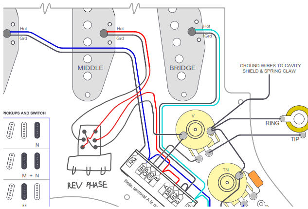 I will be getting back to you all soon! Thanks for all your help so far, thanks again for your schematic @yogi B and for understanding my ideas! Thank you gckelloch for the pickup talks, I can't wait to see how mine sound! |
|
|
|
Post by gckelloch on Jan 7, 2022 17:42:07 GMT -5
Sounds good. Say, what will be your painting/finishing procedure? I just finished finishing my first build, and it was more complicated than I expected. Water-based spray acrylic is actually a good hard clear coat option, but you need a space and a proper ventilator. I just did 2 coats of Tru-Oil on the roasted Maple neck after a 400g sanding. It was supper quick & easy and looks & feels sublime. I could have done 3 coats, but I still wanted to feel the grain. I wouldn't do more than 3, and you might want to use a white 7445 3M pad before and after the 3rd. I just used it after the 2nd coat. Stew mac sells a 3-pack of 3M pads that will come in handy for things like that. I used the gray pad to smooth the Stainless frets I filed, and then the white to polish. Works great with no mess, but where a mask.
|
|
|
|
Post by thedirestrat on Jan 8, 2022 4:30:12 GMT -5
Sounds good. Say, what will be your painting/finishing procedure? I just finished finishing my first build, and it was more complicated than I expected. Water-based spray acrylic is actually a good hard clear coat option, but you need a space and a proper ventilator. I just did 2 coats of Tru-Oil on the roasted Maple neck after a 400g sanding. It was supper quick & easy and looks & feels sublime. I could have done 3 coats, but I still wanted to feel the grain. I wouldn't do more than 3, and you might want to use a white 7445 3M pad before and after the 3rd. I just used it after the 2nd coat. Stew mac sells a 3-pack of 3M pads that will come in handy for things like that. I used the gray pad to smooth the Stainless frets I filed, and then the white to polish. Works great with no mess, but where a mask. Hey Gckelloch! Nice to hear from you after all this time! This is some great information right here! I'm got my stuff from Wudtone. They sell stains, so this is how you do it: you sand down the body with around 180 grit, then you usually got a base coat, you wipe it on with a lint free cloth, you add a few more base coats to your liking, and then when you're satisfied, you put the top coat on. And there you have it. No mask, no ventilator, no specific room, can be done in a basement. You have to wait between each coat though, like more than a day, but it's okay honestly. I also got gold highlights for mine, which I can add in the base coat, and rub into the grain to have some nice gold sparkle enter in the grain. I had to really wrap my head around the finish... I knew how to apply it but didn't know which colours to get. I was looking for a yellow, but a warmer, but still light yellow, and with some golden highlight. They just arrived today, this weekend I'm going to try doing the first coat. Really excited about the finish, and in the meantime, not right now, but this coming week, I'm going to try to figure out how to turn the Yogi B schematic into a "guitar circuitry" diagram. Just so I know where everything goes. Gonna need some help with this lol seems complicated, but I'm going to do it. |
|
|
|
Post by gckelloch on Jan 9, 2022 6:58:44 GMT -5
Sounds good. Say, what will be your painting/finishing procedure? I just finished finishing my first build, and it was more complicated than I expected. Water-based spray acrylic is actually a good hard clear coat option, but you need a space and a proper ventilator. I just did 2 coats of Tru-Oil on the roasted Maple neck after a 400g sanding. It was supper quick & easy and looks & feels sublime. I could have done 3 coats, but I still wanted to feel the grain. I wouldn't do more than 3, and you might want to use a white 7445 3M pad before and after the 3rd. I just used it after the 2nd coat. Stew mac sells a 3-pack of 3M pads that will come in handy for things like that. I used the gray pad to smooth the Stainless frets I filed, and then the white to polish. Works great with no mess, but where a mask. Hey Gckelloch! Nice to hear from you after all this time! This is some great information right here! I'm got my stuff from Wudtone. They sell stains, so this is how you do it: you sand down the body with around 180 grit, then you usually got a base coat, you wipe it on with a lint free cloth, you add a few more base coats to your liking, and then when you're satisfied, you put the top coat on. And there you have it. No mask, no ventilator, no specific room, can be done in a basement. You have to wait between each coat though, like more than a day, but it's okay honestly. I also got gold highlights for mine, which I can add in the base coat, and rub into the grain to have some nice gold sparkle enter in the grain. I had to really wrap my head around the finish... I knew how to apply it but didn't know which colours to get. I was looking for a yellow, but a warmer, but still light yellow, and with some golden highlight. They just arrived today, this weekend I'm going to try doing the first coat. Really excited about the finish, and in the meantime, not right now, but this coming week, I'm going to try to figure out how to turn the Yogi B schematic into a "guitar circuitry" diagram. Just so I know where everything goes. Gonna need some help with this lol seems complicated, but I'm going to do it. I used metallic silver acrylic paint to fill the Black Limba grain and ~2k holes I punched in with an engraver bit, but it only shows up under the trans-coat with strong light or at certain angles. Gold sparkle will cover the whole body as well as the grain pockets if you don't sand it down after applying the gold basecoat. I'd use 400g with an orbital sander for that. If you just want to fill the grain with a solid metallic hue, artist's oil paint would work better. Copper is more stunning than Gold, but do whatever works for you. Maybe look at Bronze and Brass as well. I'd also sand the body to 220g with the orbital b4 all that. Then look closely for scratches under good light, and hand-sand them out. 400g worked well for the neck. It's the smoothest feeling "raw" finish neck I have. |
|
|
|
Post by thedirestrat on Jan 11, 2022 15:30:01 GMT -5
Thanks Gckelloch!!
Thanks for the insight. I'll post some pictures of the finish when its done, still didn't start. I'm actually working on the 10 way Strat I made a thread about a while back. I'm going to turn the out of phase push pull pot into a "blower switch". Wasn't using the out of phase business anyways. For this Telecaster, it should be more interesting because of the ability to blend!
|
|
|
|
Post by thedirestrat on Jan 11, 2022 15:30:21 GMT -5
I'll post the Blower Switch schematic in my other thread.
|
|
|
|
Post by gckelloch on Jan 11, 2022 17:44:32 GMT -5
BTW, just do the flat surfaces with the orbital sander. You can wrap sandpaper around a cardboard TP roller for the inner horn surfaces, or just do those and the edges by hand. There are flexible 220g sanding foam pads as well. I covered the neck pocket with painter's tape so as to not get finish drips that would have to be filed off, but there were some drips on the top edges I had to file. You really don't want a hard finish in there that can crack under pressure. I just did 1 coat of Tru-Oil to seal it. I actually use a 1.1mm Lexan bracket in the pocket that I cut the center out of to ~1cm around the edges with scissors. The idea is to increase coupling force around the edges and minimize surface area contact. It holds the neck very rigid, and minimizes body damping for better sustain. I made b4 and after recordings that do reveal a difference. 1.1mm thick Lexan can just barely be cut with scissors. Steel washers work too, but there will be more upper-mid presence. Depends on what you prefer.
|
|
|
|
Post by thedirestrat on Jan 12, 2022 13:58:27 GMT -5
Thank you so much! For this build I will follow the Wudtone instructions, but I will keep what you said in mind for a future build  |
|
|
|
Post by thedirestrat on Jan 29, 2022 2:01:20 GMT -5
Alright, I'm starting the wiring design-- I'm trying to turn this: 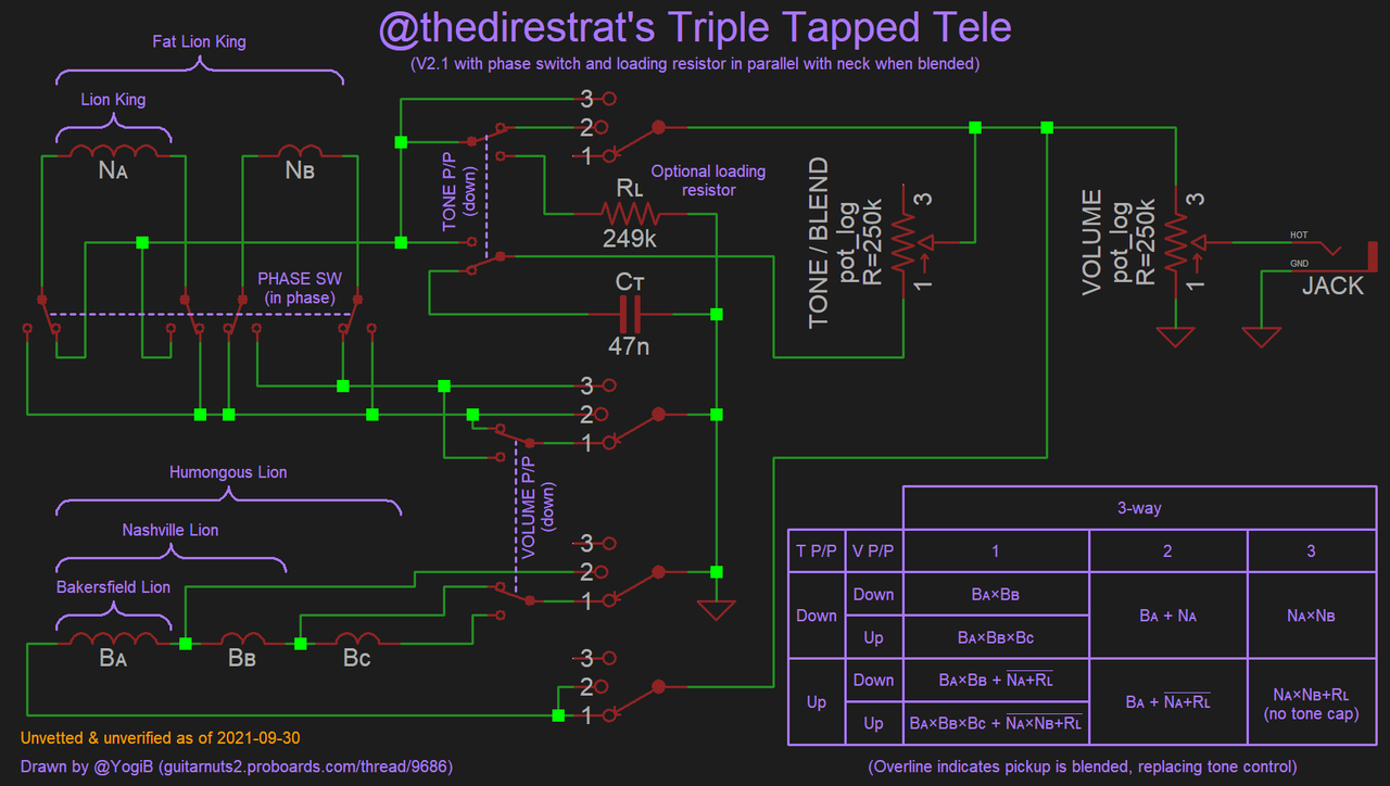 into something that looks like this: 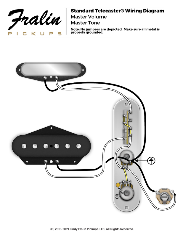 (ignore this wiring diagram, it's not what I'm doing) One thing that I don't understand is how the 4P3T. I know why I need it. With a regular DP3T switch, the whole blender/tone pot will be a bit weird... This is a normal tele switch wiring: 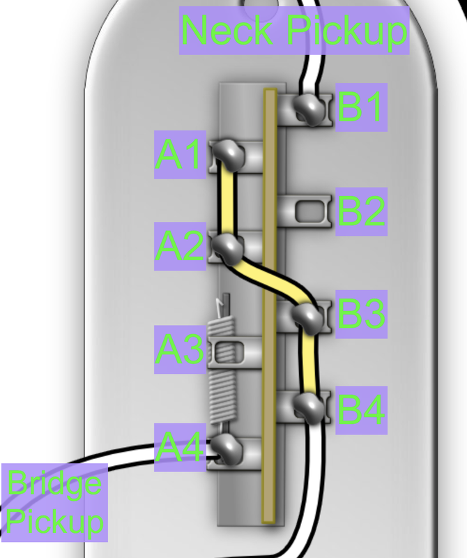 When on bridge position, A1 and A4 join in series, and B1 and B2 join. Middle = A2+A4, B1+B3. Neck = A3+A4, B1+B4. So if I choose to put the blender wire on B1, where the neck hot is, it works great for the Bridge position, but it's weird whenever the neck is selected by the pickup switch. When the neck pickup is selected, it should be totally on, but then it also sees the blend pot, which is weird. So this is why, I think, I need the 4P3T So how does this switch work. On bridge position, which lugs turn on? Same for each position. Thank you! |
|
|
|
Post by newey on Jan 29, 2022 8:50:31 GMT -5
It's not just for the blender that you need a 4 pole switch, you also need the extra poles for switching between your coil taps. I think your picture of the regular 3-way switch wiring would be easier to follow if you re-labeled A4 and B1 as the common lugs -"CA" and "CB", perhaps, and then also renumber 1,2 and 3. So, before we move on to discuss your 4P3T switch, let's designate the regular 2P3T switch in a more understanable fashion: 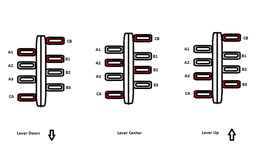 Now, the 4-pole switch may vary, so once you have the piece "in hand", you will want to check it with a meter to be sure that it operates in the way that I have shown here. But the majority of such switches should look like this and operate in this fashion: 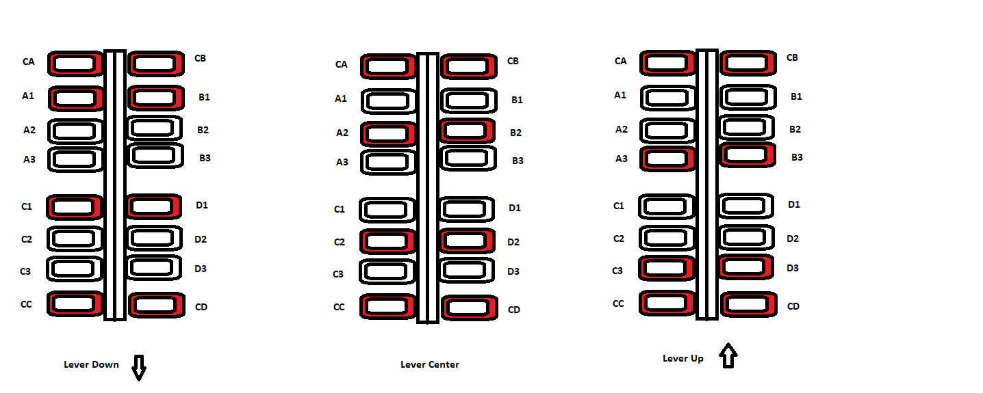 Now, the tough part is translating Yogi B's schematic drawing into a wiring diagram that you will use to do the actual soldering. In a schematic, the 4 poles of the switch may be (and are) disambiguated; they are positioned where they need to be electrically, not in actuality. So each pole of the 4-pole switch as shown on the schematic looks like this: 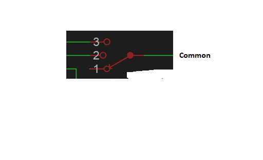 This should allow you to translate the one into the other. |
|
|
|
Post by thedirestrat on Jan 29, 2022 16:03:05 GMT -5
I think your picture of the regular 3-way switch wiring would be easier to follow if you re-labeled A4 and B1 as the common lugs -"CA" and "CB", perhaps, and then also renumber 1,2 and 3. So, before we move on to discuss your 4P3T switch, let's designate the regular 2P3T switch in a more understanable fashion: Dearest newey, this helps so much! Yes I get this now, awesome! Now, the 4-pole switch may vary, so once you have the piece "in hand", you will want to check it with a meter to be sure that it operates in the way that I have shown here. But the majority of such switches should look like this and operate in this fashion: Exactly what I was looking for! Thank you, I will make sure my switch works this way. Now, the tough part is translating Yogi B's schematic drawing into a wiring diagram that you will use to do the actual soldering. In a schematic, the 4 poles of the switch may be (and are) disambiguated; they are positioned where they need to be electrically, not in actuality. So each pole of the 4-pole switch as shown on the schematic looks like this: Exactly what I am trying to do! This is all I have left really, the hard work is all done, thanks to all of you and especially Yogi B for the schematic. So those little switches are the poles of the 4P3T switch! I see! Does the "1" represent lever down on the 4P3T diagram you sent? Does "2" mean center? Does "3" mean lever up? To translate from circuit diagram to parts I'm actually soldering, I'm breaking the overall circuit into smaller ones. So I wrote down the "grounding" circuit first, I'll be sending that one soon, and I wrote down the "blend/tone" circuit, as if I was using a normal 3P2T pickup switch. I excluded the taps, the grounding, and the out of phase switch. This one was easy because it's a standard telecaster wiring (I know how to do that) + the push pull DPDT on the tone/blend pot. Here it is: 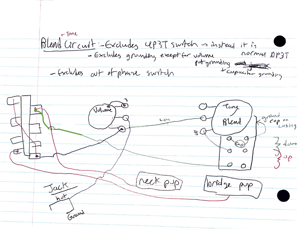 So the pickup switch doesn't make too much sense where I put the blend wire. I think it would work great for when on the bridge only position, work maybe as expected on the middle position, but weird on the neck pickup position. The neck pickup is selected, but when I pull up on the blend knob, the current will be "conflicted" right? "Do I go straight to the volume knob like the pickup switch is telling me, or do I go to the blend push pull and THEN to the volume pot?" That's a reason for the 4P3T pickup selector right? But ignoring this, everything else looks right? Even the push pull pot? Thank you! |
|
|
|
Post by thedirestrat on Jan 29, 2022 16:08:35 GMT -5
After looking at my little diagram, I don't even think the "Blend" or "Up" part of the push pull pot is right. But I will definitely look at this later.
|
|
|
|
Post by unreg on Jan 29, 2022 21:02:04 GMT -5
tds, this project is exciting and really amazing 👍😀; hope this helps you. So those little switches are the poles of the 4P3T switch! I see! Does the "1" represent lever down on the 4P3T diagram you sent? Does "2" mean center? Does "3" mean lever up? The “1”, “2”, and “3” remind me of gn2 potentiometer reference: guitarnuts2.proboards.com/thread/6612/potentiometer-orientationBut, you started this question talking 4P3T switch… |
|
|
|
Post by thedirestrat on Jan 29, 2022 22:31:40 GMT -5
tds, this project is exciting and really amazing 👍😀; hope this helps you. Omg unreg, thank you so much for you're enthusiasm! For the past 5 months I couldn't stop thinking about this thing! I'm learning so much from it, and my old Strat too, that one was a grand success, now I feel confident for this one too. You guys have helped me out sooo much, yes I came up with the idea, but it was you guys that helped me, and special thanks to Yogi B for the diagram, newey for answering many of questions and gckelloch for the pickup advice. All I have left to really do for electronics, planning wise, is translating the circuit diagram to a diagram that tells me what I need to solder. So any help here will be appreciated! I know it's pretty difficult to do, and my noobish level of knowledge only makes it harder, but I know more than ever now, and I should have outside help too. The “1”, “2”, and “3” remind me of gn2 potentiometer reference: Yes actually it reminded me of that too XD. I don't think it's that, I think it's the pickup selector lever position, because those four 123 switch things on the diagram are the poles of the 4P3T switch. |
|
|
|
Post by newey on Jan 29, 2022 22:39:02 GMT -5
Does "2" mean center? Does "3" mean lever up? "2" is the center, yes, which end is "1" or "3" is arbitrary. I drew the diagrams following the Fender convention (which more or less holds) of designating the bridge position as "1", meck as "3". Yogi's schematic does likewise. So, lever "down" is towards the bridge pickup, connects the "1" lug to the common lug, "3" is with the lever up. Note that the position of the lever is opposite of the lugs which are connected- that's why they call it a "lever switch"  . |
|
|
|
Post by thedirestrat on Jan 30, 2022 0:03:52 GMT -5
"2" is the center, yes, which end is "1" or "3" is arbitrary. I drew the diagrams following the Fender convention (which more or less holds) of designating the bridge position as "1", meck as "3". Yogi's schematic does likewise. So, lever "down" is towards the bridge pickup, connects the "1" lug to the common lug, "3" is with the lever up. Note that the position of the lever is opposite of the lugs which are connected- that's why they call it a "lever switch"  . Thanks newey!! So, in this picture:  The common lug is connected to the 1 lug = this means on my pickup selector, it's facing towards the bridge, so normally, this would mean the bridge pickup is on (I will wire it this way). Thanks for the clarification! So then on Yogi's schematic, the "default" is the bridge pickup, because it's on there for each of the "4 little switches" (the 4 poles). Also, on your 4P3T switch diagram, the one showing what all the lever positions do (which lugs are connected), which ones are the common lugs? CA, CB, CC, CD right? Where are they on the schematic? 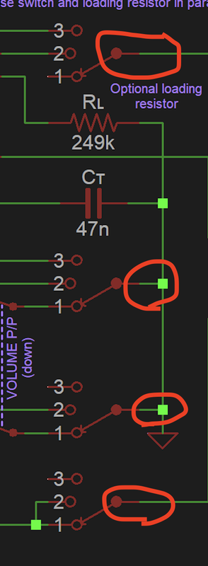 How do you know which one of these circled "lines" go to which common lug? Which one of these are CA, CB, and so on? Lastly, since the "little switches" diagrams represent one pole each, these:  are actually one of these correct: 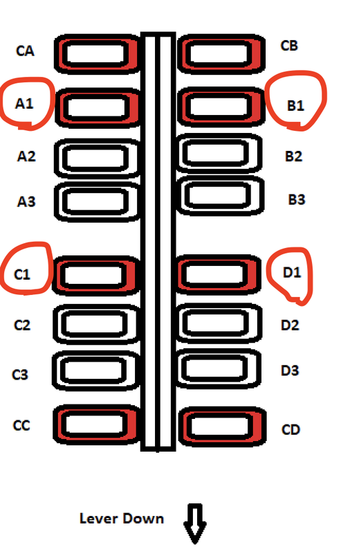 [/url] Again, how do you know which one of the lugs correspond to A1, B1, etc? Thanks as always  |
|
|
|
Post by newey on Jan 30, 2022 7:59:32 GMT -5
Again, how do you know which one of the lugs correspond to A1, B1, etc? The lettering of the poles, just like which end is "1" versus "3", is arbitrary. You can designate any one of the poles shown on Yogi's diagram to be "A", "B", etc- you just have to wire each one consistently with the diagram. Lettering the poles and numbering the other lugs is just a convenience, it's easier to talk about a particular diagram here if we can refer to "CA" rather than "the pole where the green wire attaches" or some such description. |
|
|
|
Post by sumgai on Jan 30, 2022 12:20:54 GMT -5
'dire, newey told you that the pole designations are arbitrary, and that's correct. You can, literally, say to yourself that "the upper-right pole is A", or you can call it the B pole, or C or D. We (and most of the rest of the electronics world) use designations merely for convenience in communications (which newey already said). Beyond that, poles don't need to be labeled in order - you can have A on the upper-left, and D on the upper-right, that's cool. Remember, electrons running around in your guitar don't care what you call them!  So long as you attach wires to the proper terminals for a given pole, you're golden. (Which then says, if you have a too-short wire for the pole you're currently hooking up, you might get away with moving everything on that pole to a difference pole on the physical switch, where the short wire will fit.) Along with all of this is the use of "lever up" and "lever down". That's a red-herring if ever we've seen one, because generally speaking, you can rotate the switch in its hole!* So don't worry if you get it 'backwards'.  (However, you can easily avoid this by testing the completed lash-up before installing it back into the guitar. Simply execute the "tap test" while everything is still on the workbench.) HTH sumgai * Many Telecaster models have a problem with this "solution", the cavity is too narrow. |
|