Deleted
Deleted Member
Posts: 0
Likes:
|
Post by Deleted on Nov 21, 2021 11:33:21 GMT -5
jhng- Your diagram is fine. However, I take issue with your statement as to the wire colors "South coil hot- usually green". True for stock Gibson HBs and a few others, but not true for either Dimarzio pickups or Seymour Duncan- the coils would be out of phase if either a DM or SD pickup were wired that way. There are so many variations in HB wire colors that it's usually better to just specify what wire colors one is using for the diagram, and leave it up to the user to translate the colors to whatever pickup they are using. Also note that the N coil is "hanging from hot" when the switch is in the center position. If the S coil is the one desired to be split, could wire the HB "inside out" and then connect it to the hot output instead of to ground. This would split the S coil and short the north coil to itself. Lets not get tied up with colours and go all rainbows Im not sure whats wrong with "Hanging from Hot" dam i see little birds do it all the time If i put a Prob on HOT and one at the Neg i get NOTHING, only when there is a diffence that we get a signal as for HANGING from HOT! you checked in a light switch and FOUND the LIVE wire (i did type wife there LOL) only when the Switch makes it carry back down the returning wire IT FLOWS, till then it HANGS there waiting for a point that is Different from itself HUMAN or WIRE even spider dont matter! but it is HANGING there. 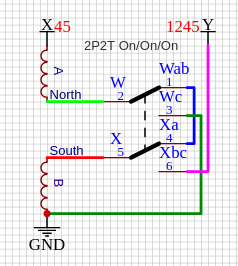 |
|
|
|
Post by jhng on Nov 21, 2021 11:38:29 GMT -5
newey, psiloguitarensis -- I am so sorry! Newey is quite right. The wire colours were misleading. I have edited that. I don't wire humbuckers myself and mistakenly thought that the Gibson colour scheme was fairly standard. Turns out that humbucker wiring is not standard at all. They all use the same colours (red, black, green, white) but all mean different things -- madness! Psiloguitarensis, you will need to check the wires on your bridge humbucker carefully to work out which of the two middle wires (that form the series link) goes to each coil. Newey is right that there is a coil hanging from hot when it is split. Unfortunately, I don't think there is a way to avoid that without losing the functionality of also using the toggle as a single coil 'bridge on' switch.
|
|
|
|
Post by psiloguitarensis on Nov 21, 2021 12:29:43 GMT -5
unreg the 6pin header boards are representation of 3way dpdt lug layout, blender pot lug location, and push pull pot lug location. i quickly noticed without that board grabbing some of the connections to cleanup image and help make it clearer where wires are going for my sane brain. jhng im cool with the B|SC|parallel mod ill draw up a diagram to insure i am understanding correctly. as i told angel i wanted to learn so now i am cramming as much info as possible so i can get my brain up to speed with yaws knowledge. i enjoy the challenge and being more helpful down the road. for me thats learning the wiring then wiring it up in my guitar and then ill always remember that setup how my mind works roughly. i gots to do it man ------------------- also jhng currently humbuck is wired =======> so should be able get those to wires correct and can assume they are n/s finish. ------------------- @angellahash is that saying north + coil lug 2 jumper 1,4 south + to common 1 with jumper to lug 4 lug 3 to ground common 2 goes common on switch btw hilarious writing with the birds great way to explain something i enjoyed that and will write that at a later laugh and reference
|
|
|
|
Post by newey on Nov 21, 2021 22:04:13 GMT -5
btw hilarious writing with the birds great way to explain something i enjoyed that and will write that at a later laugh and reference The objection to having a coil hanging from the hot end (as opposed to the ground end, which is not a problem) is not that it would fry those poor lil' birdies, but that the long length of wire in the pickup windings, if wired to the "hot" side of the output, might act as a rather long antenna and add noise to the signal. The emphasis is on the "Might act" part of that sentence- in theory it could, but we've never seen any actual real-life proof that it does so. So, we try to avoid it where possible, but accept it where, as here, it cannot be avoided with a particular scheme. |
|
|
|
Post by psiloguitarensis on Nov 21, 2021 22:10:57 GMT -5
newey not sure i understood all of what he said or you but for some reason way he put it was funny and ill get a good laugh off it when i need cheering up. though was watching video last night on bitchute i think it was guy has a hss guitar but was able to hh with a blender i thought he said but couldnt find video again my question is how does that work placing neck and mid pickup as one with a switch if mid pickup is opposite of neck
|
|
|
|
Post by newey on Nov 21, 2021 23:09:16 GMT -5
though was watching video last night on bitchute i think it was guy has a hss guitar but was able to hh with a blender i thought he said but couldnt find video again my question is how does that work placing neck and mid pickup as one with a switch if mid pickup is opposite of neck A HB, as classically wired, has its 2 coils in series. SO, if you have a HSS guitar, with the middle pickup RWRP from the neck pickup, you have your bridge HB with 2 coils in series. If you put the neck and middle pickups in series (N x M), it's like a HB with coils spaced widely apart. So, if you add the N X M combo to the bridge HB, it's sort of like a HH guitar. Presumably, in the video, he's using the blender to add the Middle in series with the neck, or vice versa. |
|
|
|
Post by psiloguitarensis on Nov 22, 2021 0:25:01 GMT -5
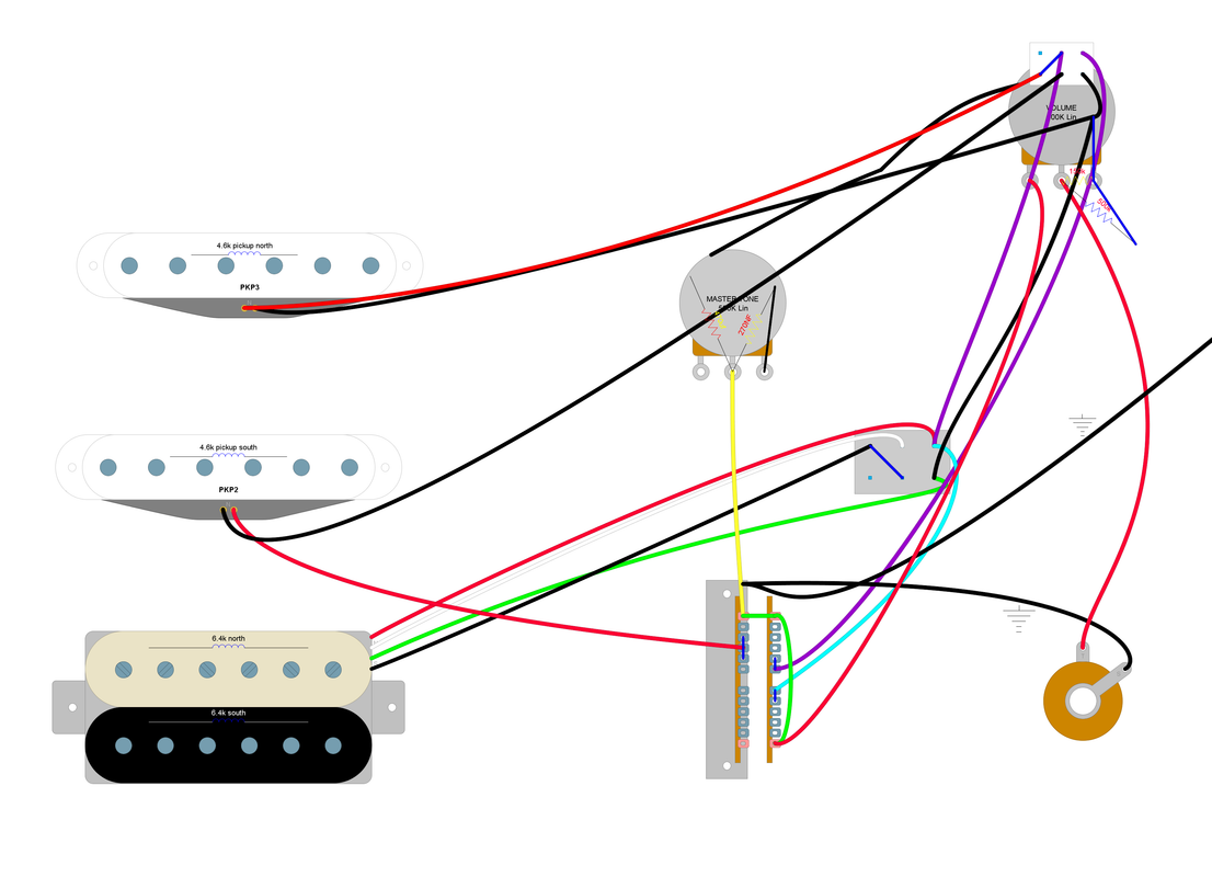 does this seem it would work then? if im right the push pull would series/parallel the neck mid pickup right? basically a wide spaced humbucker right? |
|
|
|
Post by jhng on Nov 22, 2021 4:58:57 GMT -5
You are getting there!
Half of the push-pull is good and it will put NxM (Neck and Mid in series) in positions 2 and 3. However, I'm not sure about the other half of the push pull and I'm not sure about how you have wired it to the three way switch. I think you are going to end up always having the Neck and Bridge on at the same time.
Also, some extra comments:
1. You do not need to disconnect the Neck pickup hot side when you put the Middle in series. Since the Neck is disconnected anyway in positions 2 and 3, all you need to do is move the Middle pickup ground to the Neck pickup hot. You can do this with only one side of the Push/Pull. When the Neck pickup is connected in position 4 it simply shorts out the Middle pick up. Then you will get:
1. B
2. B+(NxM) (kind of like Les Paul two humbuckers in parallel)
3. NxM (like a wide humbucker)
4. N
5. N
2. You could then use the spare side of the Push/Pull to add the Bridge pickup in position 4. So that with the Push/Pull up you get:
1. B
2. B+(NxM)
3. NxM
4. N+B
5. N
3. For position 4, you could either add the full Bridge pickup (with its three-way switch for series/split/parallel) which would give maximum options or you could add just one coil from the Bridge pick up, so that position 4 is N+B(single coil). This is like the Telecaster middle position.
You can do your original mod and my suggested variants using only the normal strat switch (if it has eight lugs rather than seven) and without using the superswitch. It requires a bit of lateral thinking, but it can be done. Then you can save the superswitch for later.
|
|
Deleted
Deleted Member
Posts: 0
Likes:
|
Post by Deleted on Nov 22, 2021 5:14:25 GMT -5
I wonder if we ignore the jack socket, volume and tone for now.
Focus on getting the switching system you want or like the look of ..
|
|
|
|
Post by newey on Nov 22, 2021 6:27:20 GMT -5
I wonder if we ignore the jack socket, volume and tone for now. Focus on getting the switching system you want or like the look of . Not a bad idea, the diagram is a bit hard to read as it is. Several points: 1) Like jhng, I can't tell if the switch wiring is correct or not. I am assuming that the black wire from the neck pickup is grounded to the back of the Vol pot where there is a "bend" in it, but hard to tell the intent there. 2) With a master V and master tone, no need to wire the tone pot off of the 5-way switch, just wire it off the Vol pot +. You can consult virtually any guitar circuit with a master V and T to see how to do so. 3) It looks like you have 2 resistors attached to the tone pot. What you need is a single cap. I can't read the lettering to know the values you are using, but I'm not sure why there are resistors there in any event. 4) You show a resistor between the wiper and the CW lug of the volume pot. If the intent is a treble bleed, it's on the wrong lugs, should be between the CCW lug ("hot" input) and the wiper. And the value looks to be way too high if it says 500K. JohnH's testing of treble bleed circuits showed the best results to be with using a 1nf cap in parallel with a 150K resistor. 5) You have an unused pole of the 5-way switch. Rather than putting the neck in series with only the middle pickup, you could use the extra pole on the Superswitch (plus the P/P) to put the neck pickup in series with whatever is selected on the 5-way switch. This would give you not only the N x M but N x B also at position 5. Position 4 would be N x (M + B). Also, without knowing the color scheme for your HB, I can't sort out the wiring to that switch. |
|
|
|
Post by psiloguitarensis on Nov 22, 2021 10:34:58 GMT -5
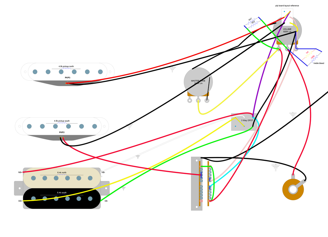 everyday i learn so much. so i found how to label stuff hopefully this helps out quite a bit to understand what wires are what. its not that im going to wire my guitar this way just extremely intrigued on how to wire and understand what all is happening when a switch is flipped/pulled or twisted. i mean i can easily become erratic and adhd and wire my guitar this way for now im going just remove one pot til i find a use for the pushpull or the blender pot |
|
Deleted
Deleted Member
Posts: 0
Likes:
|
Post by Deleted on Nov 22, 2021 10:54:35 GMT -5
 I dont normally have Paint to do this with I'm not sure whats happening with the 2P2T Push Pull switch One point you have Neck attaches to 4&5 output and Middle With no ground - Neck works but Middle Damaged Next you have Neck attached to Middle but Output sent to ground at 4&5 - Middle Works but Neck location Damaged  a way that they show a 2P2T on/on/on switch, gives me a clue how it switches The black bars show which one it favors when in the central position |
|
|
|
Post by jhng on Nov 22, 2021 11:17:50 GMT -5
As Angellahash says, it's not quite there yet. The biggest problem areas are:
1. The purple wire that goes from the three-way toggle to the push/pull switch. That basically means that the Bridge and Neck pickups are always joined together in parallel.
2. The little yellow wire that goes from the push/pull to the back of the pot. As Angellahash says, that will short circuit the guitar in positions 4 and 5, giving no sound at all.
3. The three way switch is almost right but not quite. Look over the connections for the parallel setting again.
Keep at it!
|
|
|
|
Post by newey on Nov 22, 2021 11:47:29 GMT -5
@angellahash: Your 3-way On-On-On has the center connections opposite of reality. 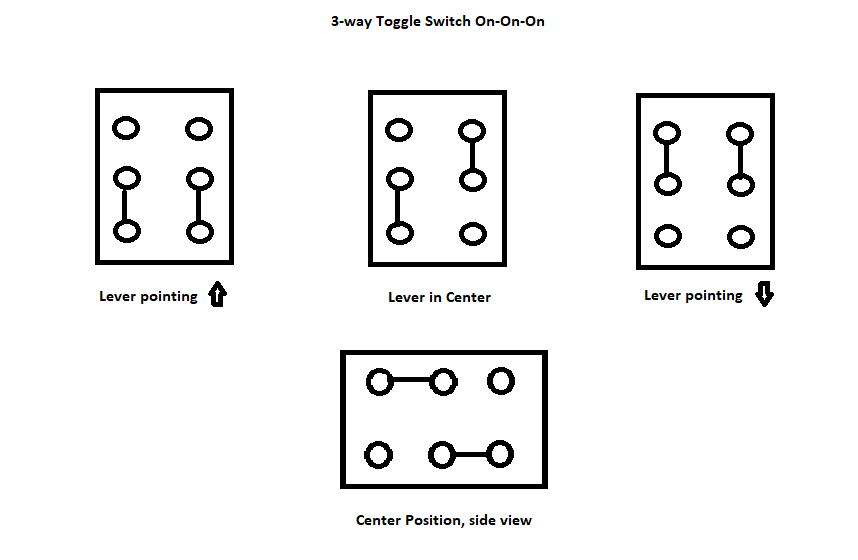 With the switch lugs vertical and facing you, bottom left connects to left-side common lug, upper right connects to right-side common lug. Note that this is symmetrical, doesn't matter which way you turn the switch. A while back, we had a member who insisted that switches configured as you have shown for the center position existed, but when challenged to point to such a switch, he was unable to do so. None of us has ever seen an On-On-On with the internal connections as you have shown them. |
|
|
|
Post by psiloguitarensis on Nov 22, 2021 12:50:33 GMT -5
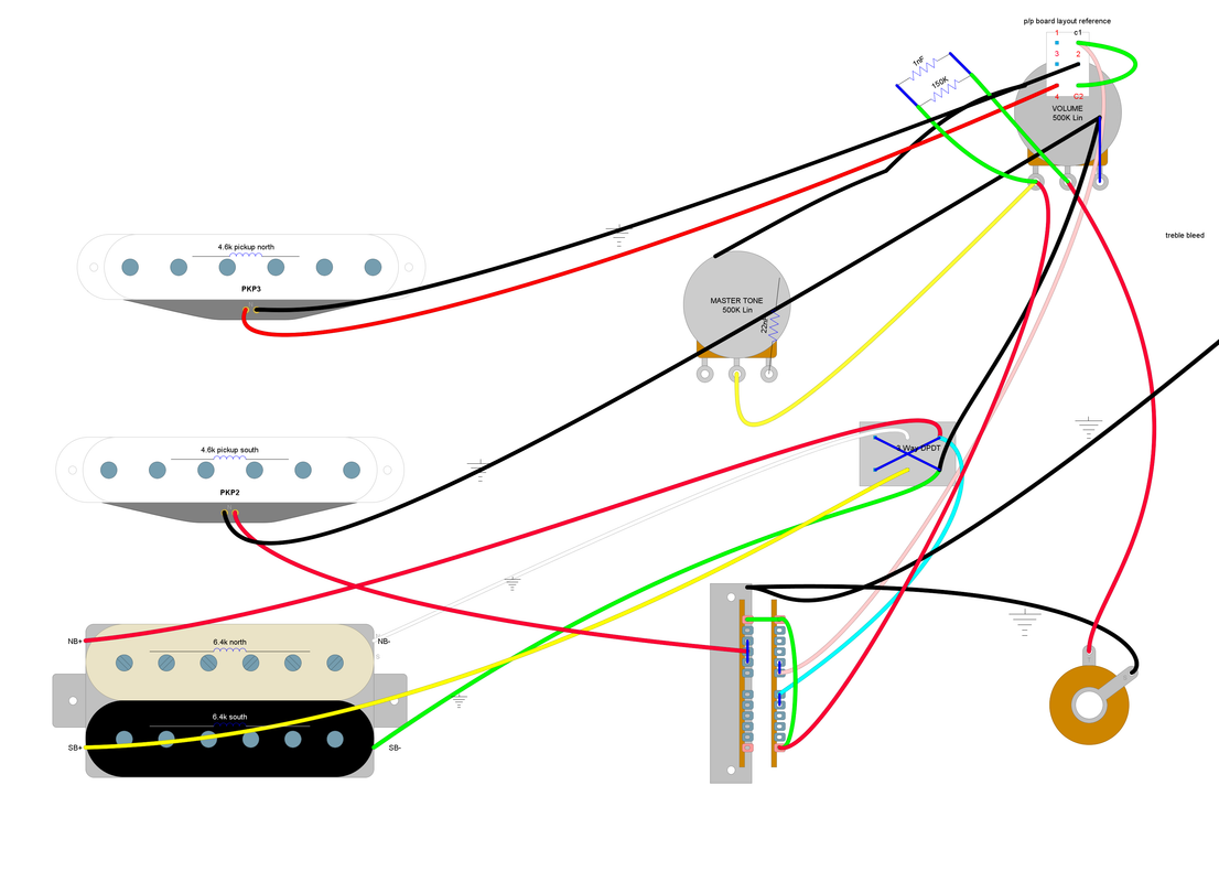 any good music store to hit in vegas leaving in few minutes and like check out a cool store |
|
Deleted
Deleted Member
Posts: 0
Likes:
|
Post by Deleted on Nov 23, 2021 6:33:39 GMT -5
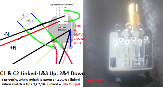 Not sure what is going on with this Push Pull switch its two Switches rolled in to one C1 and C2 Up C1 linked to 1, C2 linked to 3 Down C1 Linked to 2, C2 Linked to 4 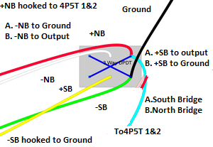 I will have to think what the Central point will do but the two ends will be North and South Bridge Pickup selection going off to the 4P5T 1&2 positions I think, im not 100% sure. Central will be ever North Bridge Pickup or South Bridge Pickup -NB still hooked to Ground and +SB hooked to Ground too or -NB to Output, and +SB hooked to Output too |
|
|
|
Post by psiloguitarensis on Nov 23, 2021 13:35:57 GMT -5
I think I understand what your saying.
output can't be a common as that's a neutral basically?
If that's a way to assume commons job.
I used to wire houses so I'm trying to relate to how I understand wiring houses.
Its why I use red for hot black for ground so often.
So technically I should be placing out with nb or sb hot
|
|
Deleted
Deleted Member
Posts: 0
Likes:
|
Post by Deleted on Nov 23, 2021 17:00:42 GMT -5
Let's take the humbucker bridge first
Two pickups North and South (call South one near the tremelo)
So four leads.
As not doing phasing (Just swapping the + and - around) we can tie -south bridge to ground and +north bridge to output as you have done.
So left with -North Bridge and +South Bridge.
North pickup on own
-North bridge to ground{+South bridge to ground}
South bridge on own
+South bridge to output {can tie -North bridge to output or leave hanging}
North and South bridge
-North bridge to ground, +South bridge to output
Humbucker
-North bridge to -south bridge
Easy thing to do is just attach -North bridge to +South bridge to make a humbucker and use a 1P2T (on/off/on) one side ground the other output meaning
North/humbucker/south
|
|
|
|
Post by psiloguitarensis on Nov 26, 2021 20:18:55 GMT -5
HAPPY THANKSGIVING
i couldnt figure how to add series with the 2p4t switch so for now i am just going the parallel coilsplit route so ill have much to enjoy. i wanted to add series with the push pull to not leave empty lugs no no problems. when i figure out how to wire the push pull for series i will but for now heres what im going to do 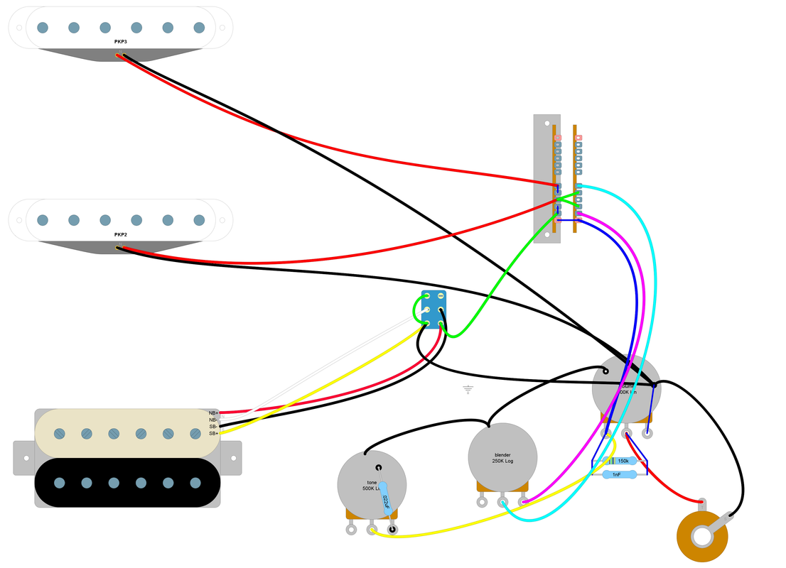 i do appreciate all ive learnt so far and cant wait to learn more
|
|
|
|
Post by psiloguitarensis on Nov 29, 2021 2:06:49 GMT -5
 so i got the series parallel working great in " DIY LayoutCreator " so i got the series parallel working great in " DIY LayoutCreator "
the switch i have for push pull is
 C1 1,3 switch is up C1 1,3 switch is up
C2 2,4 switch is down
how do i make coil split switch up and humbucker down?
when i add another dpdt to simulate the push pull pot so i can add coil split i either get coil split only or no pickups found from bridge only neck and mid in DIY Layout
how do i add a dpdt to simulate coil split mode as well with series parallel on one switch and pulling up on switch gives me north coil only?
im going to go get new strings to morrow and start my adventure. im going to get myself to the point of just needing wire c1,1,3 and c2,2,4 so it works correctly
|
|
Deleted
Deleted Member
Posts: 0
Likes:
|
Post by Deleted on Nov 29, 2021 5:22:00 GMT -5
As not sure what way could be up and down
UP would be C1 to 1 and C2 to 3
DOWN would be C1 to 2 and C2 to 4
also take a look at your Blend Pot!
|
|
|
|
Post by newey on Nov 29, 2021 6:13:12 GMT -5
@angellahash is right: You have one of the newer push/pull switches that uses a printed circuit board. But if you look at the part of the switch I have circled, it corresponds exactly to our drawings of the regular push/pull switches. You can also see the traces through the board to the solder pads up top. 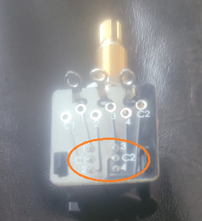 I also question whether your blend pot is right. |
|
|
|
Post by sumgai on Nov 29, 2021 12:23:12 GMT -5
The blend pot it fine, insofar as it goes. What psi forgot to do was link the Neck and Bridge leads across the switch poles. If you jumper red to cyan for the Neck, and green to magenta for the Bridge, you'll see the pot blending the "unselected" pickup into the combo of either 2 or 4 (N + M + B), and creating the combo N + B in 1 or 5. Pretty sure that JohnH has done this a time or two.  My question would be, what's the deal with that capacitor on the upper left pole?  More wires are missing, and I don't know psi's intent, so I'll forego trying to fill in the gaps.  HTH sumgai |
|
|
|
Post by sumgai on Nov 29, 2021 12:29:31 GMT -5
how do i add a dpdt to simulate coil split mode as well with series parallel on one switch and pulling up on switch gives me north coil only? Go back and look at Reply #58 in this thread, by jhng. He shows you the connections you're asking for, with explanations. |
|
|
|
Post by psiloguitarensis on Nov 29, 2021 16:45:47 GMT -5
@angellahash im understanding the switch layout and how to reference that over. issue im having is when i wire it up as such to have coil split on the push pull and series/parallel on the DPDT switch. the DPDT is correct. when i run analyze it works as should. the analyzer shows correct pickups for pos selecting . when i add a second DPDT to make into a coil splitter nothings works. i tried wiring both finishes to c1 south hot/lug 1 and grounded lug 3. i have wired the dpdt as such per post 58 as recommended and when i run analyzer it tells me no pickups can be found even neck and mid so something is incorrect and that i cant find the gremlin. newey tried that and even post your suggestion in post 7 |
|
Deleted
Deleted Member
Posts: 0
Likes:
|
Post by Deleted on Nov 30, 2021 5:31:52 GMT -5
angellahash im understanding the switch layout and how to reference that over. issue im having is when i wire it up as such to have coil split on the push pull and series/parallel on the DPDT switch. the DPDT is correct. when i run analyze it works as should. the analyzer shows correct pickups for pos selecting . when i add a second DPDT to make into a coil splitter nothings works. i tried wiring both finishes to c1 south hot/lug 1 and grounded lug 3.  i have wired the dpdt as such per post 58 as recommended and when i run analyzer it tells me no pickups can be found even neck and mid so something is incorrect and that i cant find the gremlin. -----------------------------  just typed out a whole load about split a coil without reading the dam question SORRY the FIRST switch does as you say NBxSB and NB+SB(with SB being Phased) When trying to make 2 Switches do all Combo NB, SB, NB+SB & NBxSB they have to work back to back SW1/SW2 Down/Down NB+SB, Down/Up NB, Up/Down SB, Up/Up NBxSB 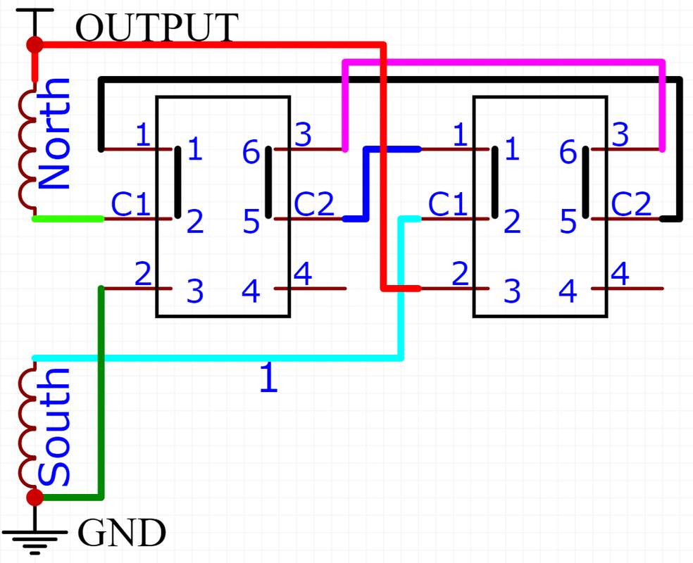 |
|
|
|
Post by jhng on Nov 30, 2021 5:52:22 GMT -5
I thought that the DPDT switch was an 'on-on-on' type. If so, then it should be wired so that it does series/split/parallel for the humbucker in the three positions. So I don't fully understand why you are also adding a push/pull switch to do another coil split?
Surely, there is no point in having a coil split on the three position DPDT switch (as part of series/split/parallel) and another separate coil split on the push/pull.
|
|
|
|
Post by psiloguitarensis on Nov 30, 2021 6:48:56 GMT -5
jhng when i wire it as such analyzer only shows parallel and split or series and split i am now starting to think the analzyer cant do on/on/on switches beyond spdt switches. though its a good layout program maybe it cant configuration in that fashion is more simplistic. the program not showing series split parallel is why i added a dpdt switch to simulate split on switch but when running analyzer it disables series parallel when second switch is add. i am not wonder cant program not configure the extra switching and thus why i only get series split, parallel split or series parallel. i also assumed for it to work correctly in program with 2 switches i would have go in this fashion HB == on/on/on == pushpull then switch is this correct?
|
|
|
|
Post by psiloguitarensis on Nov 30, 2021 7:13:41 GMT -5
@angellahash this is output from diagram you just posted 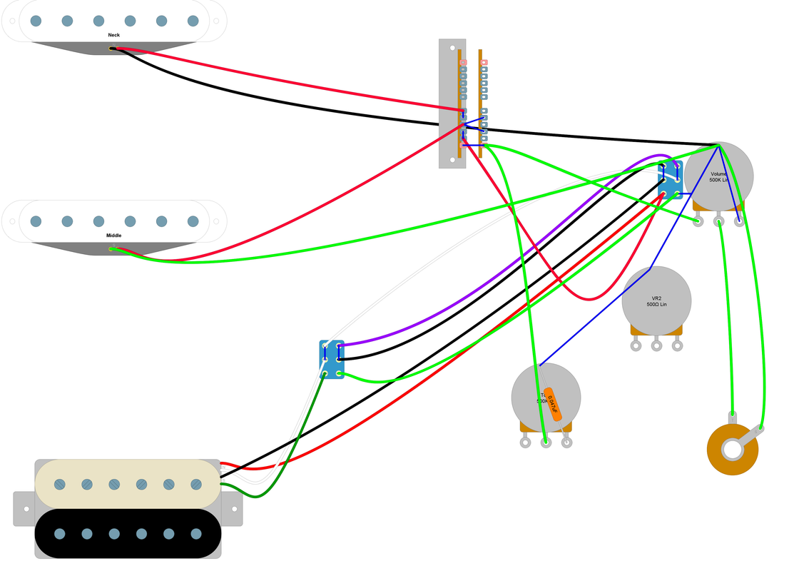 [/url] Switch configuration: [SW1.ON1:SW2.ON1:SW3.1, SW1.ON1:SW2.ON2:SW3.1, SW1.ON2:SW2.ON1:SW3.1, SW1.ON2:SW2.ON2:SW3.1] Parallel/Series connectivity tree: (Volume.1-2 + (Neck.North-> || (Tone.2-3 + ))) || Volume.2-3 Notes: 'Neck' is the only engaged pickup This configuration is NOT hum-cancelling 'Volume' potentiometer acts as a volume control for 'Neck' 'Tone' potentiometer acts as a tone control for 'Neck' Switch configuration: [SW1.ON1:SW2.ON1:SW3.2, SW1.ON1:SW2.ON2:SW3.2, SW1.ON2:SW2.ON1:SW3.2, SW1.ON2:SW2.ON2:SW3.2] Parallel/Series connectivity tree: (Volume.1-2 + (Middle.South-> || Neck.North-> || (Tone.2-3 + ))) || Volume.2-3 Notes: 'Middle' and 'Neck' pickups engaged, wired in parallel This configuration is hum-cancelling All pickup coils are wired in-phase 'Volume' potentiometer acts as a volume control for 'Middle' and 'Neck' 'Tone' potentiometer acts as a tone control for 'Middle' and 'Neck' Switch configuration: [SW1.ON1:SW2.ON1:SW3.3, SW1.ON1:SW2.ON1:SW3.4, SW1.ON1:SW2.ON2:SW3.3, SW1.ON2:SW2.ON1:SW3.3, SW1.ON2:SW2.ON2:SW3.3] Parallel/Series connectivity tree: (Volume.1-2 + (Middle.South-> || (Tone.2-3 + ))) || Volume.2-3 Notes: 'Middle' is the only engaged pickup This configuration is NOT hum-cancelling 'Volume' potentiometer acts as a volume control for 'Middle' 'Tone' potentiometer acts as a tone control for 'Middle' Switch configuration: [SW1.ON1:SW2.ON1:SW3.5] Parallel/Series connectivity tree: (Volume.1-2 + Tone.2-3 + ) || Volume.2-3 Notes: No pickups are detected in this switch configuration Switch configuration: [SW1.ON1:SW2.ON2:SW3.4, SW1.ON1:SW2.ON2:SW3.5, SW1.ON2:SW2.ON2:SW3.4, SW1.ON2:SW2.ON2:SW3.5] Parallel/Series connectivity tree: Volume.1-2 || Volume.2-3 Notes: No pickups are detected in this switch configuration Switch configuration: [SW1.ON2:SW2.ON1:SW3.4] Parallel/Series connectivity tree: (Volume.1-2 + (Bridge.North<- || Middle.South-> || (Tone.2-3 + ))) || Volume.2-3 Notes: 'Bridge' pickup wired in coil-split mode 'Middle' and 'Bridge' pickups engaged, wired in parallel This configuration is NOT hum-cancelling Some pickup coils are wired OUT-of-phase 'Volume' potentiometer acts as a volume control for 'Middle' and 'Bridge' 'Tone' potentiometer acts as a tone control for 'Middle' and 'Bridge' Switch configuration: [SW1.ON2:SW2.ON1:SW3.5] Parallel/Series connectivity tree: (Volume.1-2 + (Bridge.North<- || (Tone.2-3 + ))) || Volume.2-3 Notes: 'Bridge' pickup wired in coil-split mode 'Bridge' is the only engaged pickup This configuration is NOT hum-cancelling 'Volume' potentiometer acts as a volume control for 'Bridge' 'Tone' potentiometer acts as a tone control for 'Bridge' now if i remove jumper 6/C2 on 3way and jump 3/4 it is closest im going to get i feel and happy with these results. though would parallel sound better then series?
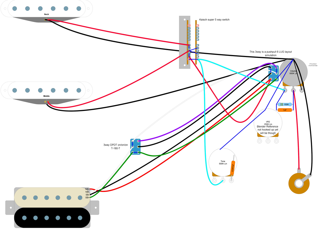
Switch configuration: [SW1.ON1:SW2.ON1:SW3.1, SW1.ON1:SW2.ON2:SW3.1, SW1.ON2:SW2.ON2:SW3.1, SW1.ON2:SW2.ON1:SW3.1] Parallel/Series connectivity tree: (Volume.1-2 + (Neck.North-> || (Tone.2-3 + ))) || Volume.2-3 Notes: 'Neck' is the only engaged pickup This configuration is NOT hum-cancelling 'Volume' potentiometer acts as a volume control for 'Neck' 'Tone' potentiometer acts as a tone control for 'Neck' Switch configuration: [SW1.ON1:SW2.ON1:SW3.2, SW1.ON1:SW2.ON2:SW3.2, SW1.ON2:SW2.ON2:SW3.2, SW1.ON2:SW2.ON1:SW3.2] Parallel/Series connectivity tree: (Volume.1-2 + (Middle.South-> || Neck.North-> || (Tone.2-3 + ))) || Volume.2-3 Notes: 'Middle' and 'Neck' pickups engaged, wired in parallel This configuration is hum-cancelling All pickup coils are wired in-phase 'Volume' potentiometer acts as a volume control for 'Middle' and 'Neck' 'Tone' potentiometer acts as a tone control for 'Middle' and 'Neck' Switch configuration: [SW1.ON1:SW2.ON1:SW3.3, SW1.ON1:SW2.ON2:SW3.3, SW1.ON2:SW2.ON2:SW3.3, SW1.ON2:SW2.ON1:SW3.3] Parallel/Series connectivity tree: (Volume.1-2 + (Middle.South-> || (Tone.2-3 + ))) || Volume.2-3 Notes: 'Middle' is the only engaged pickup This configuration is NOT hum-cancelling 'Volume' potentiometer acts as a volume control for 'Middle' 'Tone' potentiometer acts as a tone control for 'Middle' Switch configuration: [SW1.ON1:SW2.ON1:SW3.4] Parallel/Series connectivity tree: (Volume.1-2 + ((Bridge.North<- + Bridge.South<-) || Middle.South-> || (Tone.2-3 + ))) || Volume.2-3 Notes: 'Bridge' pickup wired in humbucking mode with series coils 'Middle' and 'Bridge' pickups engaged, wired in parallel This configuration is NOT hum-cancelling Some pickup coils are wired OUT-of-phase 'Volume' potentiometer acts as a volume control for 'Middle' and 'Bridge' 'Tone' potentiometer acts as a tone control for 'Middle' and 'Bridge' Switch configuration: [SW1.ON1:SW2.ON1:SW3.5] Parallel/Series connectivity tree: (Volume.1-2 + ((Bridge.North<- + Bridge.South<-) || (Tone.2-3 + ))) || Volume.2-3 Notes: 'Bridge' pickup wired in humbucking mode with series coils 'Bridge' is the only engaged pickup This configuration is hum-cancelling All pickup coils are wired in-phase 'Volume' potentiometer acts as a volume control for 'Bridge' 'Tone' potentiometer acts as a tone control for 'Bridge' Switch configuration: [SW1.ON1:SW2.ON2:SW3.4, SW1.ON2:SW2.ON2:SW3.4, SW1.ON1:SW2.ON2:SW3.5, SW1.ON2:SW2.ON2:SW3.5] Parallel/Series connectivity tree: Volume.1-2 || Volume.2-3 Notes: No pickups are detected in this switch configuration Switch configuration: [SW1.ON2:SW2.ON1:SW3.4] Parallel/Series connectivity tree: (Volume.1-2 + (Bridge.North<- || Middle.South-> || (Tone.2-3 + ))) || Volume.2-3 Notes: 'Bridge' pickup wired in coil-split mode 'Middle' and 'Bridge' pickups engaged, wired in parallel This configuration is NOT hum-cancelling Some pickup coils are wired OUT-of-phase 'Volume' potentiometer acts as a volume control for 'Middle' and 'Bridge' 'Tone' potentiometer acts as a tone control for 'Middle' and 'Bridge' Switch configuration: [SW1.ON2:SW2.ON1:SW3.5] Parallel/Series connectivity tree: (Volume.1-2 + (Bridge.North<- || (Tone.2-3 + ))) || Volume.2-3 Notes: 'Bridge' pickup wired in coil-split mode 'Bridge' is the only engaged pickup This configuration is NOT hum-cancelling 'Volume' potentiometer acts as a volume control for 'Bridge' 'Tone' potentiometer acts as a tone control for 'Bridge' |
|
Deleted
Deleted Member
Posts: 0
Likes:
|
Post by Deleted on Nov 30, 2021 8:38:12 GMT -5
The BLACK BAR between C1 & 1 and C2 & 3 was just showing how the connection is made
C1 & 1 the black bar will be LINKING them when the Push/Pull is on the UP position
C1 & 2 the black bar will be LINKING them when the Push/Pull is on the DOWN position
its showing how a Push/Pull works from the inside.
-----------------------
Push Pull will be JUST 2P2T ON/ON
-----------------
T180 is a 2P2T On/On/On, the circuit id done was for a Two Lots of 2P2T On/On
===================
Think the Goal is for you to Design your own circuit with Nudges to look at set bit
|
|