|
|
Post by cem on Feb 18, 2022 6:33:32 GMT -5
Hello everyone.
I have tried everything on my Les Paul and came to the conclusion that for me, the most usable and useful wiring is the Jimmy Page wiring, 50s style. The only thing i dislike about it is the series parallel switch. I dont think it is useful for anything. Instead, if i could get a switch that disconnects both volume and tone pots for the neck pickup, i would be able to get a brighter sound with more output which would be particularly useful for single coil tones.
I have dimarzio's on this guitar.
-Neck Volume pot: Coil split(Screw coil is active for the neck pickup)
-Bridge Volume pot: Coil split(Slug coil is active for the bridge pickup)
-Neck Tone pot: Both neck tone and neck volume pots go out of the circuit
-Bridge Tone pot: Out of phase switch
with 50's wiring
Can anyone help me with this?
|
|
|
|
Post by newey on Feb 18, 2022 7:31:16 GMT -5
Do you already have this wiring in the guitar, just with the series/parallel switch instead of what you want? Or do you need a complete diagram of the JP wiring with your modification?
If you already have the JP wiring, all you would need is a diagram of the changes to the neck tone pot wiring, since that's the only thing that will change. If you need the whole diagram, with '50's wiring and Dimarzio colors, that may take a bit of time. I searched for a JP wiring diagram with '50's wiring, and all the ones I found were SD or Gibson colors. The ones I found with DM colors weren't the Jimmy Page wiring, just regular LP diagrams. I was trying to avoid having to reinvent the whole thing here, but if you need a complete diagram, we may be starting from scratch.
|
|
|
|
Post by cem on Feb 18, 2022 9:28:09 GMT -5
Hey neweyI have seymour duncan's triple shot pickup rings on this guitar that i wan't to get rid of. So unfortunately i think i need a complete diagram. |
|
Deleted
Deleted Member
Posts: 0
Likes:
|
Post by Deleted on Feb 18, 2022 11:55:18 GMT -5
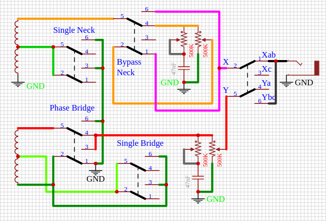 one of the most pain in the butt circuits as there is so many VERSIONS out there, all Claiming to be "JIMMY PAGE" but MOST have 500K Volume and Tone with a 47nF WISH LIST -Neck Volume pot: Coil split(Screw coil is active for the neck pickup) .. NORTH Neck ( from the Photo below ) -Bridge Volume pot: Coil split(Slug coil is active for the bridge pickup) .. NORTH Bridge ( from the Photo below ) -Neck Tone pot: Both neck tone and neck volume pots go out of the circuit .. So want a BYPASS the Tone/Volume -Bridge Tone pot: Out of phase switch .. Phased on both the Humbucker and Single Coil with 50's wiring!! guess that is the 500K and 47nF for the Tones and 500K for the Volume 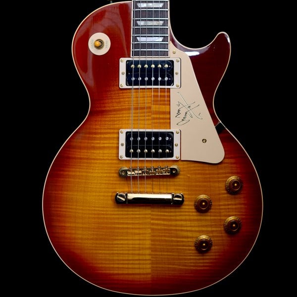 if anyone has a better image for the Toggle Switch at the end please do pass it on to me |
|
|
|
Post by newey on Feb 18, 2022 12:23:19 GMT -5
Neck Volume pot: Coil split(Screw coil is active for the neck pickup) .. NORTH Neck ( from the Photo below ) -Bridge Volume pot: Coil split(Slug coil is active for the bridge pickup) .. NORTH Bridge ( from the Photo below ) No, one of the pickups in the photo is just rotated 180°. Using DM pickups,the screw coil is the green/white pair is the screw coil and is South. Red/black is North and is the slugs. No, the '50's wiring has nothing to do with the cap or pot values. With the '50's wiring, the tone pots, instesd of being wired from the Vol CCW lug to the tone pot wiper, are wired from the volume pot wiper to the tone potCCW. The tone pot cap goes in between the Vol pot wiper and the tone CCW lug (not that it matters, it could be after the pot, too). Then the wiper of the tone pot is wired to ground. Do not ask me why anyone would wire their pots this way. To each, his or her own. No good ones I know of. JohnH uses a regular SPDT symbol, with a black dot for the center lug to indicate the center connection, like this:  |
|
|
|
Post by sumgai on Feb 18, 2022 13:18:32 GMT -5
Here's the IEEE "official" symbol for a SP3T, which is how we describe the switch used on Les Paul's, Jazzmasters, etc.:  HTH sumgai |
|
Deleted
Deleted Member
Posts: 0
Likes:
|
Post by Deleted on Feb 18, 2022 14:36:19 GMT -5
The joys of Google
You Google things and get load of different results
Why I showed a photo of the guitar showing the screw/lug and looked s Duncan diagram and still crap
|
|
|
|
Post by cem on Feb 22, 2022 13:15:05 GMT -5
The only thing i was able to find that could help is this diagram which is based on dimarzio colors: www.1728.org/jp94b.pngI'm not sure if the coils selected for the coil splits are correct in this diagram(It should be screw for the neck, slug for the bridge). If they are correct, the only thing that has to change is the series/parallel switch. And on a less important note, it should be 50's wiring as well. Would this help? Edit: Found the site where the image is from: www.1728.org/guitar9.htmIt seems like the bridge coil selected for the coil split is the screw coil. The neck coil selection is the way i want though. |
|
|
|
Post by newey on Feb 22, 2022 15:49:00 GMT -5
We're very familiar with the website 1728.org here. It is owned/run by wolf, a long-time member here, although it's been a while since he has stopped by here. His diagram wires the Neck pickup with standard DM wiring, but he wires the bridge pickup "inside out" so as to select the opposite coil from the neck when both HBs are coil split. This makes the split-coil combo hum-cancelling. With DM pickups, and as shown on his diagram, the neck pickup is wired such that the red/black coil is the active coil when split. This is the slug coil on DM pickups. The bridge HB is wired so as to select the green/white coil, which is the screw coil. This is the opposite from the way you described what you wanted in your first post. But you can still use the diagram, just swap the labels on the pickups around. Where wolf's diagram says "bridge", cross that out and write in "neck"; where the diagram says "neck", write in "bridge" instead. The wiring doesn't change, only the labeling. (Well, your phase switch will then be on the neck pickup instead of on the bridge, which makes no difference, but you can easily transfer that phase switch to the new "bridge" pickup) I will try to do a diagram based off of @angellahash's schematic later today or tomorrow. EDIT:Just FYI, to clarify:  |
|
|
|
Post by cem on Feb 22, 2022 18:10:51 GMT -5
Thanks a lot newey! I think i will wait for your diagram  |
|
|
|
Post by newey on Feb 22, 2022 19:20:30 GMT -5
OK, here's what I come up with. Let's get someone to check it before you start wiring: 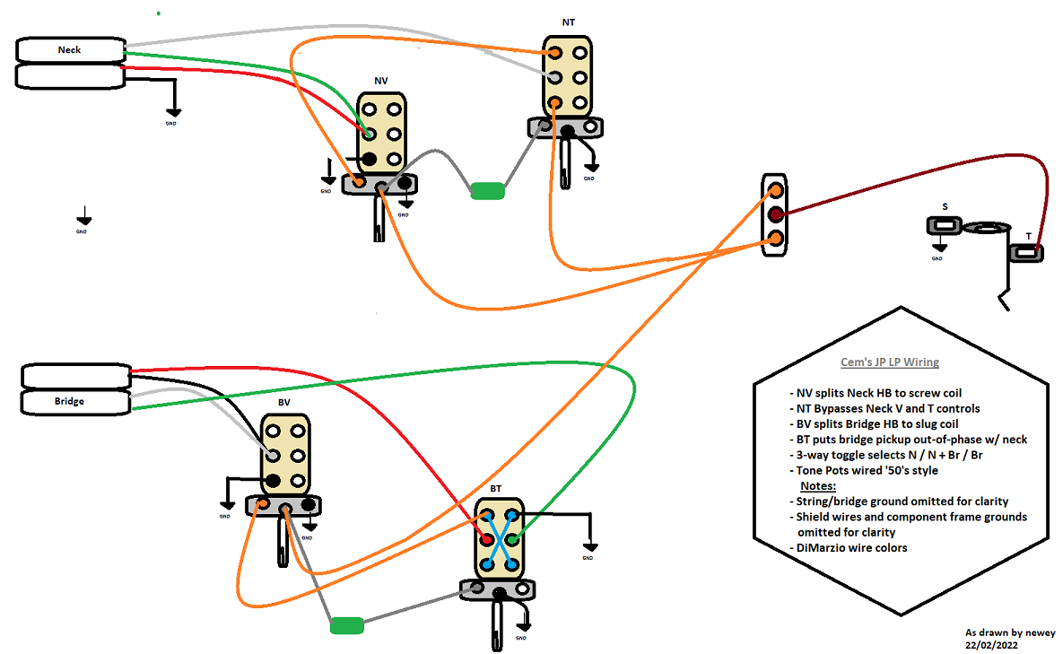 |
|
|
|
Post by sumgai on Feb 22, 2022 23:12:22 GMT -5
cem, newey's circuit, just above, works as you've wished for. 
ang, Your circuit also works, with one exception - cem's first post stated that he wants '50s wiring', and you show modern wiring. If someone wanted modern instead, then your circuit would be the way to go. HTH sumgai |
|
Deleted
Deleted Member
Posts: 0
Likes:
|
Post by Deleted on Feb 23, 2022 4:37:04 GMT -5
The tone after the volume thing
As for the by pass, mine cuts Tone/volume out. Where the other one still has tone and the volume effects the circuit still.
|
|
|
|
Post by cem on Feb 23, 2022 5:59:57 GMT -5
Thanks everyone for the help. I will try it as soon as possible  @angellahash what would the tonal difference be between yours and newey's? And how do the pots still effect the circuit when they are bypassed? |
|
|
|
Post by newey on Feb 23, 2022 6:31:35 GMT -5
As for the by pass, mine cuts Tone/volume out. Where the other one still has tone and the volume effects the circuit still. Could use the other pole of the NT push/pull to disconnect the NV wiper, I suppose. I can revise the diagram to do so if desired. |
|
Deleted
Deleted Member
Posts: 0
Likes:
|
Post by Deleted on Feb 23, 2022 6:34:11 GMT -5
 I didn't put the tone control The bypass one mine cuts it fully out for the Tone/Volume As for mine for the Tone Control part , personally I don't think it matters. If it's cutting the frequency then it doesn't matter before or after. But as your request is Jimmy Page 1950s style. So Newly but a better bypass personally |
|
|
|
Post by cem on Feb 23, 2022 7:56:20 GMT -5
As for the by pass, mine cuts Tone/volume out. Where the other one still has tone and the volume effects the circuit still. Could use the other pole of the NT push/pull to disconnect the NV wiper, I suppose. I can revise the diagram to do so if desired. I still don't understand the difference it would make. If it will improve the brightness or output, i would really like a revision but if not, it's okey the way it is. |
|
Deleted
Deleted Member
Posts: 0
Likes:
|
Post by Deleted on Feb 23, 2022 11:27:09 GMT -5
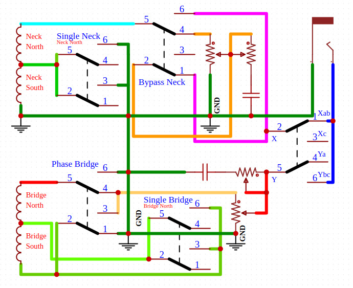 Taken off the VALUES , i've put the Tone on the other side of the Volume as for pickups, in the correct way depends on you so many people have pickups one way or another as for "JIMMY PAGE 1950s" .. the Phase hmm common.. the Coil Split.. the ONLY real thing Jimmy Page has is linking the Pickups, as Humbuckers, Single/Humbucker and as Singles. But we are taking that out for a Bypass of the Tone/Volume ------------------------------------------------------------ NON STANDARDS  So many Magical things you an do Now can put this so that when you put 10 on the Volume it by passes the Volume This is done by taking away the GROUND part of the Volume, the 2nd Wafer of the Pot when it gets to 10 Cuts off the Ground. as the Top Pot is at 10 it automatically sending the signal to the output, with no Ground to take away the signal. COULD do this with a LOW Pot say 50Ohms etc and just CUT before the Silver part on one side. 123 456 So 1) Input 2) Output 3) SIX 4) N/C 5) Ground 6) THREE in the grand system of things 50Ohms could be easy lost (ie 250K pot is 247K really so 3K lost) it would also Work with the Tone POT if you wanted to use it on that. Could make it so that the Max on the Volume also Kills the Tone pot ++++++++++++++++++++++++++++++++++++++++++++++++++++++++++++++++++++++ but if you wanted one that did so much more and i hope didnt waste a bit of space 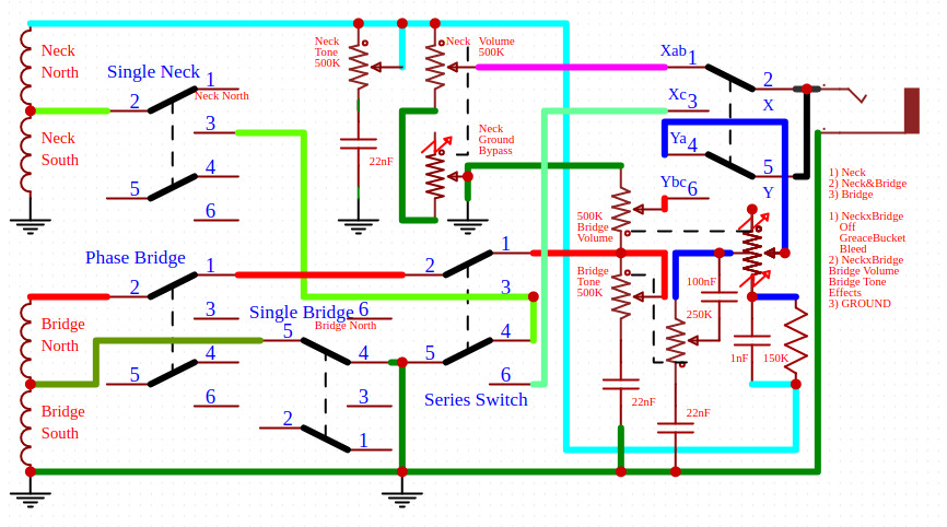 so much you can do .. just depends where you want the Passive Effects and such to happen and what |
|
|
|
Post by sumgai on Feb 23, 2022 13:53:03 GMT -5
cem, I blew it. angellahash is correct - newey's diagram does not completely cut out the Vol/Tone pots, they're still active. (Though I do see a way to make it happen as you wish....) ang's diagram is the more complete, excepting that thing about modern versus '50s wiring.
ang, As newey points out above, and has been discussed several times here in The NutzHouse (we even have a stickied thread on the topic), when the Vol pot in a guitar using '50s wiring is turned down even a little bit, the Tone pot becomes both a tone and volume pot - it interacts with the Vol pot to present a varying load to the pickup, and that raises havoc with the guitar's tone. Turning down the Vol even further just exacerbates the issue, usually to the point of uselessness. Which is why we all went to 'modern' wiring, even though some manufacturers resorted to 'backwards' wiring to alleviate certain blending issues. HTH sumgai |
|
|
|
Post by cem on Feb 23, 2022 17:54:38 GMT -5
Thank you all for sharing your valuable knowledge but i am quite confused. I have already sent newey's diagram to my guitar tech and i'm not sure if he started yet. I really want to know what newey's version of neck bypass would sound like as opposed to angellahash's version. If it is a slight difference then i will go with newey's diagram since it has 50's wiring(tried both modern and 50's and liked the latter) and is clearer. Because I don't think my tech will be able to read angellahash's style of drawing. So does newey's bypass work at all? If so it's fine by me. But if not, i am in dire need of newey's diagram to be revised. Thanks again in advance  |
|
Deleted
Deleted Member
Posts: 0
Likes:
|
Post by Deleted on Feb 23, 2022 20:05:52 GMT -5
Thank you all for sharing your valuable knowledge but i am quite confused. I have already sent newey's diagram to my guitar tech and i'm not sure if he started yet. I really want to know what newey's version of neck bypass would sound like as opposed to angellahash's version. If it is a slight difference then i will go with newey's diagram since it has 50's wiring(tried both modern and 50's and liked the latter) and is clearer. Because I don't think my tech will be able to read angellahash's style of drawing. So does newey's bypass work at all? If so it's fine by me. But if not, i am in dire need of newey's diagram to be revised. Thanks again in advance  Hmm. Well as the main goal was the bypass of the volume and tone. They are both still in play, it's worse than that you can ground the signal WTF is a Guitar Tech! |
|
|
|
Post by newey on Feb 23, 2022 23:12:08 GMT -5
Well, then, I guess I'd better get on it, if'n it's a "dire need" type of situation. Tour starting next week or something?  . . . Even if he has, the changes are trivial, just desoldering one wire and adding one new one. @angellahash: All good now? 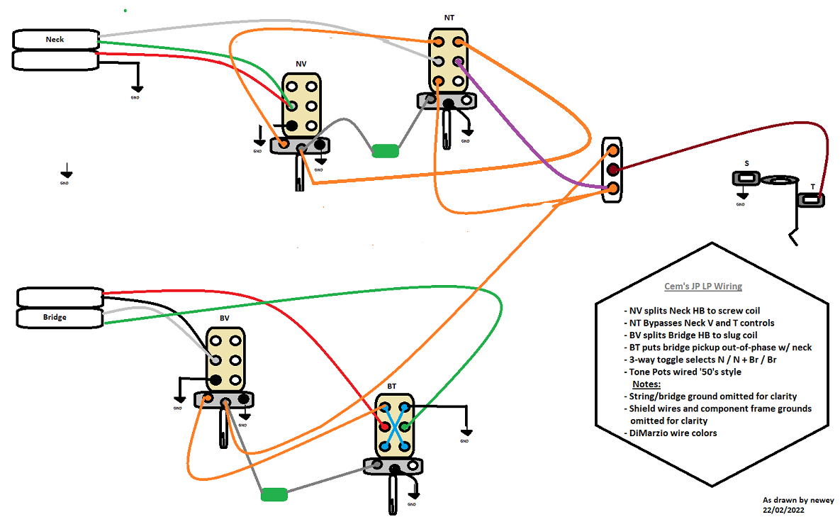 |
|
Deleted
Deleted Member
Posts: 0
Likes:
|
Post by Deleted on Feb 24, 2022 8:34:28 GMT -5
you are ADMIN Newey but ok .. PAT ON the HEAD good Boy  |
|
|
|
Post by sumgai on Feb 24, 2022 13:04:05 GMT -5
cem, newey's latest is correct in all regards, ask your tech to make the slight changes, they're easy. (And FWIW, there's no need for a second long wire to the pickup selector - just solder in a short jumper between the lower-left terminal and the right-center terminals on the push-pull switch. Same effect (same electrical path), but less wire all jumbled up in the small cavity. Reduces the chance of burning something with the soldering iron.  ) This latest version uses what we call a "True Bypass", and I'm ashamed to admit that years ago I posted a diagram on this in the Modules section. Time is taking its toll on my memory. Good thing we've got some new blood in here, and hopefully it's young enough to stick around for the next decade or two.  HTH sumgai |
|
|
|
Post by cem on Feb 25, 2022 4:33:24 GMT -5
Thank you all so much. It's been exactly one week since my first post and you guys were able to finish the diagram so quick and i'm grateful  Just to be clear, which wire to the pickup selector should i omit after adding the jumper? The purple one or the orange one? Edit: After taking a look at the older diagram i'm pretty sure that it's the orange one that i need to omit. Right? |
|
|
|
Post by sumgai on Feb 26, 2022 0:56:42 GMT -5
cem,
Well, either wire could be taken out, so just for simplicity, I'll volunteer the orange one to go away. So long as a short jumper wire is soldered between those two terminals, it'll work as designed.
Post sound clips in the Sound Samples forum! (Found under the Chillin' Off Stage category.)
HTH
sumgai
|
|
|
|
Post by cem on Jan 12, 2023 12:42:38 GMT -5
Hello everyone. It's been a while. I hope you are all doing well:) I have been playing my Les Paul as my primary guitar of choice on stage and am quite happy with it. Especially the Volume/tone pot bypass switch makes the guitar extremely versatile. I get p90ish, single coil-like tones without the output drop you get from coil splitting. But I never find myself using the out of phase switch. Instead of that, i want the bypass switch for the bridge pup as well. I'm posting the final version of the diagram since i forgot to post it after sumgai made the final correction. So i am asking this just to be safe: Should i just copy the top half of the diagram and just wire it the same way for the bridge pickup in order to change the out of phase switch to a volume/tone bypass? As always thanks in advance. 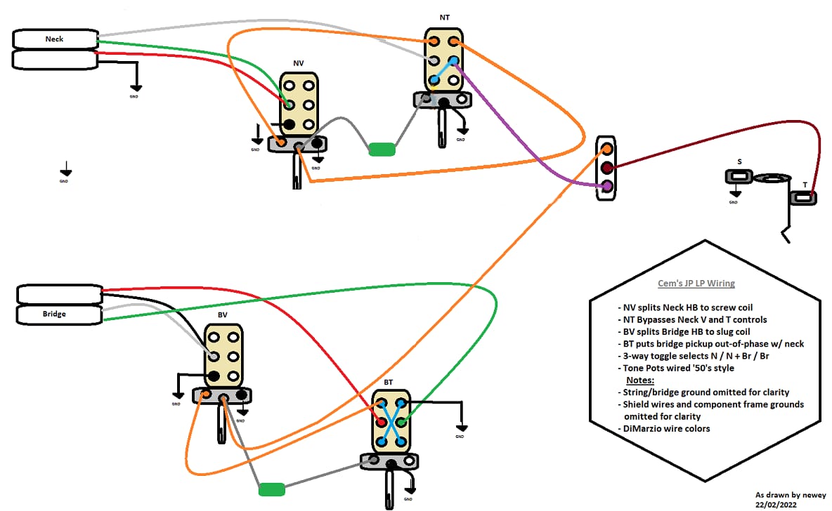 |
|
|
|
Post by cem on Jan 30, 2023 16:22:47 GMT -5
Help  |
|
|
|
Post by stevewf on Jan 30, 2023 18:18:37 GMT -5
if anyone has a better image for the Toggle Switch at the end please do pass it on to me Well, I don't know if it's better, but at least it's in EasyEDA, which I think @angellahash is also using:  I made that recently when faced with the same issue. But I see a couple problems off the bat: - If you don't use EasyEDA, it might not make sense to use this. - It doesn't show as well as other drawings show that there are exactly 3 positions. - I don't know how to share EasyEDA work. MattB once shared some of his own custom EasyEDA drawings, and I still don't understand how! |
|
|
|
Post by cem on Jan 30, 2023 20:03:57 GMT -5
Help me  |
|