gpdb
Meter Reader 1st Class

Posts: 66
Likes: 5
|
Post by gpdb on Jun 16, 2022 13:10:56 GMT -5
Hi All, I've been collecting and measuring lots of pickups recently, and I came across something interesting. The Dimarzio Evolution Bridge and Neck both have a roughly similar DCR (14.2, 12.3), but their main difference is that the bridge uses a taller ceramic magnet (.25"), while the neck uses the standard ceramic magnet (.125"). Both pickups have the same inductance value of 6.7H. I've read before from Bedlam Guitar's page (https://bedlamguitars.wordpress.com/technical-info/pickup-magnet-swapping/) that iron seems to account for the change in Inductance values with magnets. With both of these pickups using ceramic which doesn't contain iron, this reading makes sense.  However, I then looked at my Dimarzio Titan set. These pickups are very similar in construction to the Evolution set with the bridge using a .25" ceramic and the neck using a .125" ceramic. Also, the coils are identical in DCR (10.8), so the only difference is the magnet. However, the inductance values were different (6.68, 6.22). The only last difference between both sets was pole pieces. The Evolution set uses thicker hex screws, and both sets poles do not protrude past the baseplate. The Titan's use smaller hex screws, which you typically see on other brands. The Titan's screws also protrude through the bottom of the baseplate, farther in the neck than the bridge. So I hypothesized that if I was to unscrew the poles to be at the same point where the bridge poles were, would the inductance values be matched? 
 Interestingly, the inductance did go up when unscrewing the poles, though not all the way to the level that the bridge was. I was able to increase the inductance value from 6.22H to 6.49H. My hypothesis also didn't pan out though, as it appeared the position of the screws and baseplate didn't have any affect as I could remove the baseplate entirely and not see a change. At this point though, I'm a bit stumped. Maybe the two pickups themselves just have enough differences to make them not equal each other in Inductance (.2H isn't a massive amount), but if the Evolution set has the same inductance, then the Titan set should have the same inductance. I did create a bode plot for all 3 options, and the resonant peak of the neck model with poles raised was reduced to the same level of the bridge. Any comments would be appreciated. I bet if I made another bode plot and switched the magnets between the Titan Neck and Bridge, I would still have an inductance value of 6.49 but the plots would be very close.   Here's all the unloaded plots of the Titans  Lastly, here's an image of the Evolution but loaded. Surprisingly the magnet doesn't seem like it's making much of a difference here. I wonder if the pole pieces are causing this? You can see that the Titan bridge and neck have a much bigger difference in plot. Maybe the thick hex screws don't conduct the magnetism very well since they don't use keeper bars. 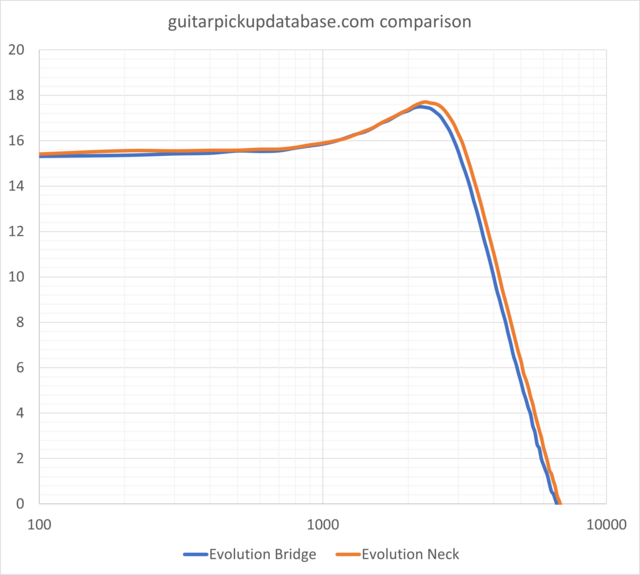 |
|
|
|
Post by ms on Jun 17, 2022 6:14:17 GMT -5
Plenty of iron in Ferrite (https://en.wikipedia.org/wiki/Ferrite_(magnet)). Steel pole pieces raise inductance; more steel can raise it more, and extending them past the ends of the coil can also raise the inductance because it keeps more flux inside the coil by making the field lines straighter near the ends of the coil.
Example: It appears that a PAF type humbucker is designed to have the same sensitivity to hum fields in both coils to get good cancelation. The screw poles are thinner, but they extend outside the coil on the bottom. I think this is for better balance.
|
|
gpdb
Meter Reader 1st Class
Posts: 66
Likes: 5
|
Post by gpdb on Jun 17, 2022 10:37:09 GMT -5
If that's the case though, then how does the Evolution set basically appear identical in inductance, but the Titans don't? They're both using the same magnets in bridge and neck, but only in one case is the inductance different. Does the larger magnet affect the thinner pole pieces in a way that doesn't get affected with the thicker screws? It just doesn't make any sense. Especially when comparing both sets curves, the evolution set appears to be indistinguishable, where as the Titans are clearly different.
|
|
gpdb
Meter Reader 1st Class
Posts: 66
Likes: 5
|
Post by gpdb on Jun 17, 2022 10:53:19 GMT -5
Also separately - how are the evolution charts identical, when the gauss at the poles is almost double for the bridge than the neck? All the other pickups I've tested with bigger magnets in them seem to read higher dB overall. Maybe I did something wrong... but I measured them back to back. Generally I see a result like the Titans.
|
|
|
|
Post by ms on Jun 17, 2022 11:48:31 GMT -5
I think the first thing to understand is why the B and N of the evol have the same inductance. Presumably the B has more turns since it has a higher resistance; why is the inductance not higher? It must have something to do with the magnets. Ceramic magnets should not directly affect the inductance (low permeability), but there is an indirect effect. The thicker magnet on the B could be stronger and might move the poles further along their hysteresis curve to where the permeability is lower, canceling out the effect of more turns. I am guessing that the designer wanted to use a stronger magnet on the B, and then noticed that the inductance decreased. So he (or she) increased the number of turns to bring the inductance back up.
OK, lot of speculation here.
|
|
gpdb
Meter Reader 1st Class
Posts: 66
Likes: 5
|
Post by gpdb on Jun 19, 2022 11:02:08 GMT -5
What's strange though is that this is a unique case - when looking at the Titan's we're not seeing the same observations, even though they have the same magnets. So wouldn't that mean it's related to the pole pieces? The Evo Bridge and neck are slightly different in DCR, but it doesn't see large enough to make a large difference in inductance. In fact the Evo neck actually measured slightly higher at 6.73H than the Bridge, which was 6.7. I could take both magnets out of them and measure but the magnets seemed like they were glued in, I couldn't get the baseplate off when I tried. As far as the pole pieces though, they only touch the magnet along the screws cutting edge, so there's a lot less contact with the magnet than with keeper bars. Although I guess that keeper bars still have screws inside those, so maybe it's the same. But they also have a lot less distance since they're smaller.
Do you have any literature I should look up to understand what a hysteresis curve is? I haven't heard of that before.
|
|
|
|
Post by ms on Jun 20, 2022 5:52:55 GMT -5
|
|
gpdb
Meter Reader 1st Class
Posts: 66
Likes: 5
|
Post by gpdb on Jun 20, 2022 9:35:32 GMT -5
This makes sense, thank you for the link. I don't have a physics background but I've always got a passion for learning  On the section titled "Hysteresis in Magnetic Recording", it's talking about how an input signal can increase the magnetism of the material. Would this input signal be a guitar string in our case? Or is it talking about a separate magnetic field, like being in the presence of a stronger magnet? |
|
gpdb
Meter Reader 1st Class
Posts: 66
Likes: 5
|
Post by gpdb on Jun 21, 2022 11:45:59 GMT -5
I've got a theory. The Dimarzio Evolution uses Dual Resonance, which just means that the coils have different wire gauges on each bobbin. I originally assumed that both pickups used the same wire gauges, something like 42 and 43 AWG. However, I was looking at the coils, and I noticed the bridge pickup's south coil looked slightly smaller than the neck's south coil. If you look back at the image at the top, you can see it. So I measured each coil and here's what I got:
| Series DCR | Series Ind. | Series Cap. | North Coil DCR | North Coil Ind. | North Coil Cap. | South Coil DCR | South Coil Ind. | South Coil Cap. | | Evolution Bridge | 14.2 | 6.7H | 123.6pF | 6 | 2.89H | 104.2pF | 8.2 | 3.03H | 195.7pF | | Evolution Neck | 12.4 | 6.7H | 111.5pF | 5.44 | 2.88H | 109.2pF | 6.83 | 3H | 148.6pF |
Looking at the south coils of each, they both have an inductance of 3H, even though the bridge has 1.2kohms more resistance and ~50pF more capacitance. So my theory is that the south coil of the bridge is 44 AWG, and the neck south coil is 43 AWG. That would account for the equal inductance values.
|
|
|
|
Post by ms on Jun 21, 2022 13:13:44 GMT -5
Yes, a difference in the wire sizes makes sense. Changing the wire size to one size smaller makes the resistance rise by 1.26 times. You are measuring 1.20, close enough in the real world.
I do not see why they do this, nor why they call it dual resonance. The primary resonance of a pickup is a result of the inductances of the two coils in series, and the cable capacitance in parallel with the capacitances of the two coils in series. I suppose that there could be some subtle differences well above this resonance.
|
|
gpdb
Meter Reader 1st Class
Posts: 66
Likes: 5
|
Post by gpdb on Jun 21, 2022 14:54:24 GMT -5
Wow, I wasn't aware that reducing wire size increases resistance by 1.26 times... that must mean they literally didn't even change the turn count, they just changed the wire gauge. It's so funny digging into this stuff and realizing this is just people, making simple decisions. I get the "Dual Resonance" marketing lingo, it's just to make it sound cool. I haven't tested this yet, but if you were to create a curve in parallel, would you see a real dual resonance?
|
|
veliko
Rookie Solder Flinger

Posts: 7
Likes: 0
|
Post by veliko on Jun 23, 2022 10:40:27 GMT -5
I've got a theory. The Dimarzio Evolution uses Dual Resonance, which just means that the coils have different wire gauges on each bobbin. I originally assumed that both pickups used the same wire gauges, something like 42 and 43 AWG. However, I was looking at the coils, and I noticed the bridge pickup's south coil looked slightly smaller than the neck's south coil. If you look back at the image at the top, you can see it. So I measured each coil and here's what I got:
| Series DCR | Series Ind. | Series Cap. | North Coil DCR | North Coil Ind. | North Coil Cap. | South Coil DCR | South Coil Ind. | South Coil Cap. | | Evolution Bridge | 14.2 | 6.7H | 123.6pF | 6 | 2.89H | 104.2pF | 8.2 | 3.03H | 195.7pF | | Evolution Neck | 12.4 | 6.7H | 111.5pF | 5.44 | 2.88H | 109.2pF | 6.83 | 3H | 148.6pF |
Looking at the south coils of each, they both have an inductance of 3H, even though the bridge has 1.2kohms more resistance and ~50pF more capacitance. So my theory is that the south coil of the bridge is 44 AWG, and the neck south coil is 43 AWG. That would account for the equal inductance values. You are quite close the truth I believe. As you pointed out the south coil of the evolution bridge is smaller implying that it is using a smaller gauge of wire. What I did was in jdguitarworks - pickup calculator based on the pictures you shared in the beginning of the thread, tried to match the degree to which the bobbin is filled and the got the following results. Given that visually bobbins on the pictures are roughly 80-85% filled in the calculator I set wire thickness to AWG 43 (single insulation build) for the North coil resulting in 6300 turns out of 7280 max turns (69/80 layers) which seems to agree with the posted pictures. For the South coil I set the wire gauge to AWG 45 yielding 5780 turns out of possible 12 270 (49/104 layers) and that also seems to agree with the images as the south coil looks "half full". Although my estimates are rather empirical I would claim here that there is no conundrum. You have a coil with slightly less conductive material, the south coil, and that is later accounted for by the thicker magnet equalizing the the bridge's inductance to the one of the neck pickup. As ms pointed out ceramic magnets aren't entirely void of iron so they contribute to inductance. In the case of the titan set we have bobbins filled to roughly the same degree and i can say within reasonable certainty based on the resistance reading you provided and confirmed by the aforementioned calculator that the titan set is using AWG 43 wire gauge and the 0.46H difference is accounted for by the thicker magnet. That is roughly your contribution to inductance by the ceramic magnet and is most probably the difference in Inductance in the evolution set in the coils alone.  In the picture above I quoted resistances for the most common wire gauges that I got from Martin Koch's book for building guitars. It is incorrect to say that resistance changes by 1.2 simply by changing to the next thinner wire gauge. since resistance is measured in Ohms per unit length for AWG 42 it's 5.4 Ohms/meter and AWG 43 is 7.0 Ohms/m (a factor of 1.296) then you need to now the length of the wire used. You can see in the top of the sketch that the innermost turns on a 52mm bobbin give 0.646 Ohms/turn while if the bobbin is fully packed with wire the final turns will contribute with 0.85 ohms/turn. For example if you have a 50mm spaced humbucker bobbin fully packed with AWG 42 wire you will have a DRC of 4400 Ohms at 5830 turns which the same bobbin fully packed with AWG 43 wire will give you a DCR of 7050 Ohms at 7270 turns. That gives you a factor of 1.6 for changing a wire gauge 42 to 43 for a fully wound bobbin. And this is all assuming you are a consistent winding technique. So with some simple math and that pickup calculator you can iteratively figure out the wire used in a pickup by looking at the degree to which the bobbin is filled, the DC resistance and some qualified guesses. Hope this cleared out some of the uncertainties I am also just learning about the more complicated stuff. |
|
|
|
Post by ms on Jun 23, 2022 13:18:48 GMT -5
The definition of AWG is here: www.powerstream.com/Wire_Size.htm. Changing three wire sizes changes the resistance by a factor of 2. For one wire size it is the cube root of 2, that is, 1.2599.... Compounds that contain iron might or might not have high permeability, and thus might or might not potentially affect the inductance much. For example silicon (transformer) steel might have a relative permeability of 1500, while an AlNiCo (an iron alloy) magnet might have 4. Ferrite (ceramic) used for a permanent magnet is low, but ferrite with low permanent capability can be high. Also, the ceramic magnet in these humbuckers is not inside the core where it can affect the inductance significantly. So the ceramic magnet material should have almost no effect on the inductance, (but remember that the permanent field might change the permeability of the steel cores). No, I did not account for the change in length of wire when changing wire size. I am not convinced you can make this work out without accounting for the change in core permeability when the strength of the permanent magnet is changed, but that, of course, is just one factor among all these. |
|
|
|
Post by antigua on Jun 23, 2022 15:35:27 GMT -5
I think those coils can be taken apart, so you can check the inductance of the two coils without any cores at all and see how they vary. The neatness, or lack of neatness also affects the inductance, because it changes the coupling coefficient from one turn to the next, but you will get a much clearer picture than measuring the coils with their cores in place.
|
|
veliko
Rookie Solder Flinger
Posts: 7
Likes: 0
|
Post by veliko on Jun 23, 2022 17:39:50 GMT -5
ms Just so there is no misunderstandings it was more of a remark to gpdb. I am still pretty new to all of this and I bet it's you who has a lot to teach me. As far as factors between wire gauges go, I'd just check the manufacturer spec sheet. I just gave an example what the factor difference between wire gauges is and then 2 fully wound bobbins to show that you can't compare them apples to apples as there's a bit more to it. But it is simple enough to reverse engineer with some simple tools. I did give heads up of the empiricism of my approach and there are definitely things I have not accounted for. My goal was to present model that makes sense with the given info given that a lot of the other variables were the same. But yeah I have no clue how much the magnet affects the Inductance quantitatively. In any case the situation makes sense to me. Post edit: Thi could make for a very quick and informative experiment, Take an existing pickup with a 0.125in ceramic magnet measure the inductance and swap it with a 0.25 trick ceramic bar magnet (of hopefully the same composition) and find out if it affects the Inductance. Nothing besides the magnet should be changed for consistency purposes and by using ceramic magnets we avoid the variable of gauss that would otherwise be present in AlNiCo magnets.
|
|


 On the section titled "Hysteresis in Magnetic Recording", it's talking about how an input signal can increase the magnetism of the material. Would this input signal be a guitar string in our case? Or is it talking about a separate magnetic field, like being in the presence of a stronger magnet?

