|
|
Post by ChrisK on Jul 17, 2006 16:45:41 GMT -5
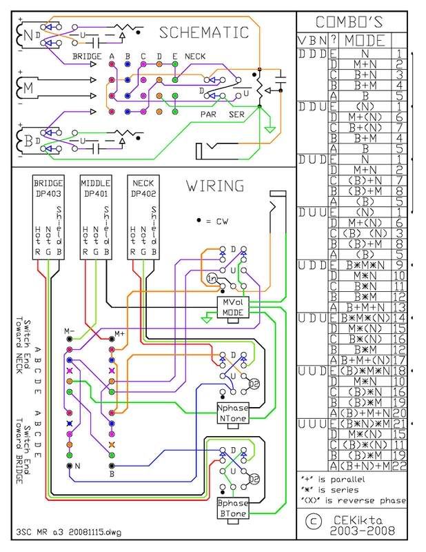
As implemented a few years back in the Padouk Caster (in the Gallery). 20081115 Updated and rearranged drawing for clarity. This is what it does ("+" is parallel, "*" is series): Mode switch down A. Bridge (Middle + Neck are shunted) B. Bridge + Middle C. Bridge + Neck D. Middle + Neck E. Neck (Bridge * Middle are shunted) Mode switch up A. Bridge + Middle + Neck B. Bridge * Middle C. Bridge * Neck D. Middle * Neck E. Bridge * Middle * Neck Wiring the tone controls as shown really helps in the series modes. Adding the phase switches really helps overall.  The old drawing; i37.photobucket.com/albums/e84/cekikta/Wiring/Padouk3SCMRa2S.jpg[/IMG]Note: Since originally posted, there was a missing connection for pole [M-] position [D] to signal ground. It is shown in the schematic at the top. It was alluded to in the wiring diagram by the mysterious "X" at position [D] on the [B+] pole. The winner of this lottery was andywelsh on 3Apr2008. His prize is only the certainty of really knowing that he really knows.  |
|
zamzara
Apprentice Shielder
 
Posts: 49
Likes: 0
|
Post by zamzara on Jul 11, 2007 4:11:39 GMT -5
I have found an easter egg with this design. I changed my B+M+N setting to M only, however:
On my superswitch there are 'in between' positions, similar to the stock fender switch, where two sets of contacts are switched on. These give B+M+N in positions 2½ and 3½ in stock mode, and (I think) B*(M+N) and N*(B+M) in series mode. It's fiddly to set the switch there but it could be useful in a studio situation.
|
|