|
|
Post by busydoingnothing on Jan 22, 2011 22:35:17 GMT -5
Thanks again guys. I'm pretty new to guitar wiring, so could you clarify on the humcancelling with both singles selected? Is there a way to address it? And what exactly is the "hanging from hot" issue? What's the result?
Also, if I can make one final request...how difficult would it be to skip the switch for phase selection? I want to try wiring it up without the phase switch at first so I can keep the stock look. I'll throw the switch in if I decide I need it. Sorry to be such a pain >_<
I have all the parts and I'm ready to get this goin. I'm pretty nervous but I love soldering, so it should be fun.
|
|
|
|
Post by newey on Jan 22, 2011 23:59:40 GMT -5
The phase switch is a module of this design, it can be easily removed. The hot and "not hot" leads from the neck pickup, which currently go to the middle terminals on the phase switch, are connected instead to the next component in line, as shown.
The "hanging from hot" issue is, perhaps, a non-issue. There is a theoretical possibility of increased noise from a coil disconnected at the ground end, but still connected ("hanging") from the hot output lead.
Many folks have wired schemes with a hanging coil and reported no problems. In theory, the additional length of "antenna" formed by the hanging coil might increase noise, particularly in an environment which is electrically noisy to start with. But there is no certainty that it results in a real-world problem.
In any event, this can be redrawn (I think) to eliminate the hanging issue, although I may need JohnH's assistance to do so, as currently, I'm not seeing it.
You can just follow JohnH's lead, or I'll redraw it, but it may be a few days before I can get to it.
As far as coil selection, one North coil coupled with a South will give humcanceling, which means rewiring my scheme as John suggested above. As drawn, it selects the South coils, and thus will not be humcanceling, assuming the coils are oriented the same between the 2 pickups.
If your pickups are oriented the same (and they probably are, since they're the same brand), this means either joining both inner coils, or both outer coils, to achieve hum cancellation. Many folks prefer using the outer coils in this scenario, so as to use the bridge coil closest to the bridge for max brightness/treble. String travel being what it is, the slight difference in the position of the coils at the neck position likely doesn't make an audible difference, whereas at the bridge it may- so you chose based upon the bridge coil.
|
|
|
|
Post by wolf on Jan 23, 2011 0:21:31 GMT -5
busydoingnothingI redrew the diagram with the phase switch removed.  I hope I drew that correctly. neweyIt didn't seem to bother the folks that designed Seymour Duncan Triple Shots™. Their wiring allows a "hanging from hot" condition.
|
|
|
|
Post by busydoingnothing on Feb 3, 2011 19:17:01 GMT -5
Hey guys, I got all the parts and I'm ready to get down and dirty. Total newb question here...looking at the switches, what orientation are they? I wanna make sure I don't get things backwards. Looking at the picture above, is the switch switched towards the neck or the bridge?
Also, when grounding the cap to the tone pot, does it matter where I solder it? On the old regular pot, it was just soldered to flat bottom part of the pot, and obviously the push/pull doesn't have that. Would the outer ring do, or should I solder to the side of the boxy part? I'm so technical here...
Thanks again! I'm excited.
EDIT: OH! And the pickups both bare wire. I don't know what it is nor what to do with it. It was previously soldered to the same spot as the green wire.
|
|
|
|
Post by newey on Feb 3, 2011 19:47:40 GMT -5
This is the shield, it goes to wherever your ground point is. If you're using the back of a pot, that's fine.
Once again, it should go to your grounding point. Most P/Ps have a small nub on one side at the base to use to ground the case; you can use that, but it may be tough to get multiple grounds soldered on there. You may want to "star ground", collecting all the grounds at a lug connector or a screw into the side of the cavity.
They aren't really in any orientation, since we haven't defined where they go on the real guitar. You just have to translate the wiring to your actual guitar. You can always "mirror image" the diagram if you need the switches to operate the other way around.
|
|
|
|
Post by 4real on Feb 3, 2011 20:39:38 GMT -5
On push pull pots especially...I use a file to the back side of the pot and pre-tin it with plenty of solder (but neatly) before starting...this gives good grounding points. Be careful not to use excessive heat for two long. Filing a pot makes it easy. The switch part/box of the Push pulls can be delicate...the metal is very thin and heats quickly and there are plastic sliding parts right up against them that can melt. I think it better to avoid heating these up at all. 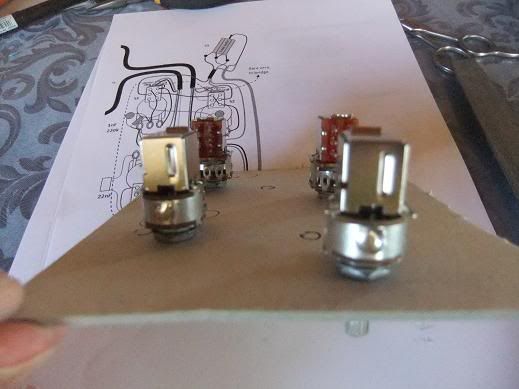 Also, I use a cardboard template where there is no pickguard. For which way the switches work...see how the slide connects the terminals...or leave enough length of wiring to enable you to reverse them rather than have to re-solder everything to get it right. Bare pickup wires go to ground. Eventually everything should end up going to ground and if shielding or neatness, I tend to screw in a tiny screw to the cavity...perhaps a brass washer behind it that I can solder to...but the back of the pots are generally sufficient as a grounding point. ... The phase switch removal should be ok...just be aware that it is easy to get pups out of phase, so you may need to exchange the wires if that is the result perhaps...from your diagram it looks ok! |
|
|
|
Post by busydoingnothing on Feb 3, 2011 21:24:30 GMT -5
|
|
|
|
Post by newey on Feb 3, 2011 21:42:05 GMT -5
Yes, as shown on the diagram, L to R, the slide switches give:
series / SC / parallel
If you want the parallel setting to be closest to the neck, then you should be good to go, just orient the switch as shown in the diagram.
To do the opposite, you'd need to mirror image the wiring left to right.
Doesn't really matter which way you do it, so long as both slide switches are the same.
|
|
|
|
Post by busydoingnothing on Feb 3, 2011 21:49:37 GMT -5
Awesome, got it. I can't thank you enough for all your help! I'll keep you posted on how it goes.
|
|
|
|
Post by busydoingnothing on Feb 3, 2011 22:22:27 GMT -5
The bridge is the one without the ground, right? So ditch the bare wire?
|
|
|
|
Post by busydoingnothing on Feb 3, 2011 22:42:22 GMT -5
Also, if I'm switching the neck to do the north coil per John's instructions, do any of the jumper wires or wires going to the pots get swapped? Or do those all stay in the same spots?
|
|
|
|
Post by newey on Feb 3, 2011 23:50:59 GMT -5
JohnH said:
But I've looked at this and I don't see how that does it. And, I've stared at this too long now . .
Perhaps someone else would like to take a stab at getting the North coil only- while still keeping it in phase with the Bridge pup. At the moment, I'm lost . . .
|
|
|
|
Post by busydoingnothing on Feb 5, 2011 17:44:25 GMT -5
Anyone? JohnH, can you clarify when you get a chance?
|
|
|
|
Post by busydoingnothing on Feb 11, 2011 11:09:18 GMT -5
No one?
|
|
|
|
Post by newey on Feb 11, 2011 14:11:58 GMT -5
BDN-
I didn't mean to leave you hanging like that. I'm at work right now, but let me take another look at this over the weekend and I'll see if I can figure it out.
|
|
|
|
Post by JohnH on Feb 11, 2011 16:23:35 GMT -5
Hello, I hadnt had a chance to look at this thread again this week. Can you post or clarify again which of the above diagrams you are considering? my comments were relative to neweys module diagram at post 20. Im going out soon but I should be able to post again this weekend. Also, what wiring colour code system do your pickups follow?
John
|
|
|
|
Post by newey on Feb 11, 2011 16:39:38 GMT -5
JohnH-
I believe he's following Wolf's redrawing of my diagram at Post 32, without the phase switch. I can't seem to wrap my head around getting the other coil, I seem to get no output at all in the center position when I switch both pairs of wires around.
|
|
|
|
Post by newey on Feb 11, 2011 21:19:29 GMT -5
OK, I think this has got it. Pay no attention to the order in which the wires emerge from the pickup, watch the colors alone. Bl and Wh are one coil, Gr and Red are the other.  If someone would vet that for me (and for BDN) it would be appreciated. |
|
|
|
Post by JohnH on Feb 12, 2011 16:29:29 GMT -5
newey - I think that works, for the switching and main humcancelling. If anyone is interested in also avoiding 'hanging from hot' issues (slight possible further reduction of noise), I believe that can also be taken care of, both at the coil switching and pickup switching level. To avoid hanging from hot of the disused coils of each pup, the ground and hot outputs from the slide switches can be swapped. To return the coil wire colours to nearer convention, having done this, they get moved too:  Secondly, the 'binary tree' pickup switching can employ their spare poles to avoid 'H from H' in the pickup switching, like this:  A bit more wiring to do, but maybe slightly better. These diagrams assume Seymour Duncan colours, and the bridge cuts to the screw coil, and neck to slug coil, if they follow convention. cheers John |
|
|
|
Post by busydoingnothing on Feb 12, 2011 19:25:31 GMT -5
So it looks like the second diagram is the way to go to fix all the problems?
|
|
|
|
Post by JohnH on Feb 12, 2011 19:41:14 GMT -5
yes, thats what I would do
J
|
|
|
|
Post by busydoingnothing on Feb 12, 2011 19:57:01 GMT -5
Awesome, thank you so much guys! I'll get to it tomorrow. Cheers!
|
|
|
|
Post by busydoingnothing on Feb 13, 2011 14:21:55 GMT -5
Hey guys, I'm wiring it up now. I'm looking at the bridge pickup and I don't see where it gets grounded. Am I missing something? Where do I solder the bare wire off of the bridge pickup?
|
|
|
|
Post by JohnH on Feb 13, 2011 14:31:20 GMT -5
Yes, the diagram only shows the wires to the coils. Any bare wires are also to be grounded. These connect to the case or back of the pups, to screen them, but they dont carry any signal. For the signal wires, the bridge gets grounded when needed by the switching.
|
|
|
|
Post by busydoingnothing on Feb 13, 2011 14:40:46 GMT -5
Can I attach the bare wire off of both the neck and bridge to the post on the switch where the green wire for the neck pickup goes? Looks like that one goes to ground.
|
|
|
|
Post by newey on Feb 13, 2011 14:49:14 GMT -5
Probably would work that way, but a better practice is to leave the shielding connections (the bare wires) out of the signal path of the pickup coils. Attach the bare wires to the same point you are using to ground everything else, like wherever the tone capacitor grounds to, for example.
|
|
|
|
Post by busydoingnothing on Feb 13, 2011 19:41:33 GMT -5
I got it all wired up...now the fun troubleshooting begins. I only get sound when I touch the tip of the cable to the bridge piece or the control plate and touch one of the screws on the switches. I have the tone cap grounded to the bridge piece. I have the two bare pup wires soldered together and grounded to the cavity piece. I also have that ground connected to the top left peg on the tone pot where the green connects in the diagram. Did I do any of those wrong?
|
|
|
|
Post by newey on Feb 13, 2011 20:55:45 GMT -5
BDN-
Perhaps not shown on the diagram as it should be, but the outjack neg., which is connected to the vol pot neg, also needs to be grounded.
|
|
|
|
Post by busydoingnothing on Feb 14, 2011 2:23:24 GMT -5
newey, I think that was my problem, I didn't have both of my grounds connected (rookie mistake). It seems like all the switching is in-tact. Just so I understand the coil split, am I still getting *some* output from the unused coil? When I put the switches in the middle position and touch a screw to the unused coil, I can still hear the ticking, but it's much quieter than the used coil.
|
|
|
|
Post by JohnH on Feb 14, 2011 3:55:04 GMT -5
That sounds like it might be right. Its not actually the unused coil that is still giving a click, its just that the coils are coupled magnetically so a pulse on the pole of the disused coil induces a small output in the other active coil.
John
|
|


