tw0409
Apprentice Shielder

Posts: 31
Likes: 0
|
Post by tw0409 on Nov 22, 2011 14:27:30 GMT -5
I preference will be putting the bridge parallel and bridge parallel on the pushed pots....since it make sense to me that if I need more power I can pulled them to get it.
As for the "On" switch, I think I will try it for my next project. The current one seems enough for me to play with for a while...
Cynical and Newey thanks for the guidance! I really appreciate it! Now....The second reason I am here is that the wiring guru can actually produce the plan we've been talking about! Again, thanks for the help.
The spec, I am looking for is:
SD JBJr bridge
dimarzio Cruiser middle
SD lil 59 neck
1 master volume and 1 master Tone. Both push/pull. The Neck parallel/series is controlled by vol pot. The bridge parallel/series is controlled by tone pot.
1) neck parallel
2) neck parallel+middle series
3) middle series
4) bridge parallel
5) bridge parallel+neck parallel
Let me know if anything is not reasonable!
Thanks
|
|
|
|
Post by newey on Nov 22, 2011 18:35:59 GMT -5
Let's clarify exactly what we're talking about here, before we get to a diagram for this:
A) P/P pot selects series/parallel for Bridge HB coils
B) Another P/P pot selects series/parallel for the neck HB coils
C) 5-way switch, using a 4P5T Superswitch, selects:
1) Neck HB (in series or parallel, depending on P/P)
2) Neck HB (in series or parallel, depending on P/P) + Middle Series HB
3) Middle series HB
4) Bridge HB (in series or parallel, depending on P/P)
5) Bridge HB (in series or parallel, depending on P/P) + Neck HB (in series or parallel, depending on P/P)
I'll do a diagram once it is confirmed that's what you want, tw.
It looks like a good scheme, the only change I might make (and this is entirely a matter of your personal preference) would be to put the N + B setting at position 4 and the bridge alone at position 5.
That way, both the neck and bridge HBs are at each end of the 5-way switch. It's easier to access the settings at the ends of the 5-way than the ones in the middle, and it's nice to be able to quickly move to the bridge pup alone for lead work.
|
|
tw0409
Apprentice Shielder
Posts: 31
Likes: 0
|
Post by tw0409 on Nov 22, 2011 22:01:16 GMT -5
Let's clarify exactly what we're talking about here, before we get to a diagram for this: A) P/P pot selects series/parallel for Bridge HB coils B) Another P/P pot selects series/parallel for the neck HB coils C) 5-way switch, using a 4P5T Superswitch, selects: 1) Neck HB (in series or parallel, depending on P/P) 2) Neck HB (in series or parallel, depending on P/P) + Middle Series HB 3) Middle series HB 4) Bridge HB (in series or parallel, depending on P/P) 5) Bridge HB (in series or parallel, depending on P/P) + Neck HB (in series or parallel, depending on P/P) I'll do a diagram once it is confirmed that's what you want, tw. It looks like a good scheme, the only change I might make (and this is entirely a matter of your personal preference) would be to put the N + B setting at position 4 and the bridge alone at position 5. That way, both the neck and bridge HBs are at each end of the 5-way switch. It's easier to access the settings at the ends of the 5-way than the ones in the middle, and it's nice to be able to quickly move to the bridge pup alone for lead work. Yes, that is exactly I wanted. On the 5 way super switch or the "default" of neck and bridge is parallel. The DPDT's can switch them to series. Also, just a reminder...can you please convert the colors of the 4 conductors according to the brand? thanks. And...other small things. I am planning to use 250k pots like SD does in the diagram. For tone cap, I am going to try .033uf. Not as usual as .022 or.047... looks like a good middle ground. I hope it won't sound bad. It's been my pleasure working with you guys! |
|
|
|
Post by newey on Nov 23, 2011 0:20:49 GMT -5
There is no "default" wiring. The push/pull pot gives you both coils in series one way and in parallel the other, and that wiring is then carried over to the 5-way switch. The position of the P/P dictates what you have, series or parallel, and the 5-way switch has nothing to do with it.
|
|
tw0409
Apprentice Shielder
Posts: 31
Likes: 0
|
Post by tw0409 on Nov 23, 2011 0:27:02 GMT -5
There is no "default" wiring. The push/pull pot gives you both coils in series one way and in parallel the other, and that wiring is then carried over to the 5-way switch. The position of the P/P dictates what you have, series or parallel, and the 5-way switch has nothing to do with it. Now I understand. I thought there is another circuit going on at the switch and the p/p will switch from the 5 way to the switch's circuit. |
|
|
|
Post by newey on Nov 23, 2011 6:49:38 GMT -5
tw- Here is a schematic to do what you want. The neck and bridge pups each get their own series/parallel switch, and a 5-way Superswitch then handles the inter-pickup switching. Notice that we only use 3 out of the 4 poles on the Superswitch. This might be able to be simplified down to use only 2 poles, and there is a 2-pole "half Superswitch available, but those are tough to find and the price is about the same as the full SS. The neck and bridge pups use SD colors, the middle is DM colors, as you specified. Now, a couple of things. First, don't trust my diagrams until someone else signs off on it. Second, this is a schematic. A schematic shows the electrical relationships between components, but does not show their physical locations. For example, the DPDT switches are shown separate from the V and T pots, even though they are physically attaches to each other. A wiring diagram, on the other hand, does show where things are actually located, and shows all the wires betwen the components. A wiring diagram is better for wiring it all up We try here to teach folks to do things for themselves. Your assignment is to translate this schematic (once someone else vets it) into a wiring diagram which you can then use to wire your guitar. As the old saying goes, "Give a man a fish and he eats for a day. Teach a man to fish, and he'll be gone all weekend, and come back drunk and full of lies . . . ". Or something like that . . .  Ask questions, take a stab at drawing up a wiring diagram, we'll help you as needed. 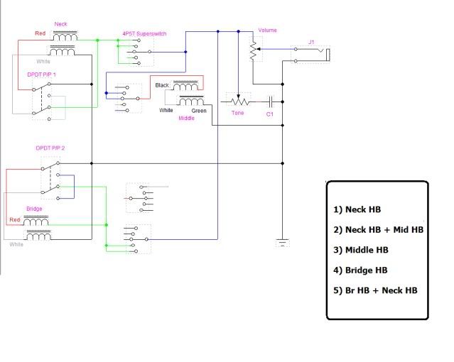 |
|
tw0409
Apprentice Shielder
Posts: 31
Likes: 0
|
Post by tw0409 on Nov 23, 2011 20:28:35 GMT -5
The 4P5T and DPDT are hard to understand. For 4P5T, I can see the lugs are divided into four groups, which resemble your schematics. However, I see the middle lug of each group is extended with another lug. It matches what I see on the switch, but I am not sure what does the "extended-out" lug represent.
For DPDT, there are six lugs on the schematics, but the orientation confuses me. Isn't it oriented 3 on one side and 3 on the other? I don't understand why they are divided into four and two lugs
|
|
|
|
Post by cynical1 on Nov 23, 2011 21:25:00 GMT -5
The 4P5T and DPDT are hard to understand. For 4P5T, I can see the lugs are divided into four groups, which resemble your schematics. However, I see the middle lug of each group is extended with another lug. It matches what I see on the switch, but I am not sure what does the "extended-out" lug represent. Does this diagram help?  OK, this is how you switch works:  And this is how it gets wired for series\parallel:  Now, your next question, what is DiMarzio and Seymour Duncan start and finish...north and south... Well, because I'm feeling generous, use this: | Pickup Manufacturer | Adjustable Pole.......... | ............. | .......... | Slug Pole.......... | ............. | .......... | | Start "A" | Finish " B" | M.P. | Start "C" | Finish "D" | M.P. | DiMarzio
Humbucker | Green- | White | South | Red+ | Black | North | Seymour Duncan
Humbucker | Green- | Red | South | Black | White | North |
Now, since you've got mini-humbuckers, this may not be totally accurate, so an e-mail to DiMarzio and Seymour Duncan wouldn't be a bad idea. OK, have at it and make us proud. Happy Trails Cynical One |
|
|
|
Post by newey on Nov 24, 2011 9:11:05 GMT -5
tw-
the 4P5T switch, as it is in the schematic rendering, has one connection coming out one way (L or R, depending on whether that pole was "flipped" in the drawing) The side with the single connection corresponds with the "common" or "pole" connection on the switch drawing- located at the end of each pole on the atual switch.
|
|
tw0409
Apprentice Shielder
Posts: 31
Likes: 0
|
Post by tw0409 on Nov 25, 2011 4:05:30 GMT -5
Alright... here it comes. (I forget to draw the output lead and the lug to ground on the vol pot..... well I think this make it less confusing...  ) I have done my best on this diagram. Some wires "jump" over when they cross with others. The ends of each leads are denoted. e.g. BB for Bridge Black. I also wanted to use one common ground...maybe a nut to gather all the ground wires before sending them to output jacket ground. I hope I did fine.  |
|
|
|
Post by newey on Nov 25, 2011 9:21:22 GMT -5
tw- Not bad for a first attempt. Not right, mind you, but you're close. The 5-way wiring looks correct, except that you only have the middle pickup at position 3, you're missing a jumper to position 2 so that you get the N + M at position 2. A bigger problem are the DPDT switches. They're both wrong, you need to look at the example Cyn1 posted above (which is correct with the schematic). The two wires, which each go to the center common lugs, have to get attached to each other to form the "series junction" for the series setting. Yours never connect together. In the other switch position, one goes to hot, the other goes to ground. Other than those items, it looks OK, but recall that I still need someone to sign off on my schematic- if that's not correct, then it's "garbage in-garbage out". I'm about 90% sure it's OK, but as anyone who hangs out here will tell you, I'm wrong on a fairly frequent basis.  |
|
tw0409
Apprentice Shielder
Posts: 31
Likes: 0
|
Post by tw0409 on Nov 25, 2011 10:15:10 GMT -5
Okay. Let me try one more time to get it right! I thought cynical have read and approved it?? He said nothing so I assume it's good?  |
|
|
|
Post by cynical1 on Nov 25, 2011 11:07:08 GMT -5
I thought cynical have read and approved it?? He said nothing so I assume it's good? ...and you know what happens when you assume... Yeah, newey's right, it's close, and not bad for a first attempt. Take a look at the component drawings I posted, think about what ChrisK used to call the "signal path". Ask yourself, if I'm a happy little guitar note, and I follow these wires, where will I end up? Chris also stressed designing in modules. For example, your series\parallel switches are a module. A signal comes in, gets processed, and goes out. Tying these modules together creates a circuit. So, draw out how the push pulls work. Draw out the switch wiring. Now, connect them to the pots and out to the jack. By breaking it down into smaller bites it's easier to digest. And the idea of Star Grounding is a very good one. If you want to incorporate that into your drawing please go right ahead. I like it because when it comes to wiring the final project I know how many grounds I've got to have, I can do a quick count to make sure I didn't miss one, and it saves me from heating up a tone or volume pot to attach multiple wires to. I know it's a lot more involved then that, and I shank more then my fair share, but your design is solid and a good one to cut your teeth on. Feel free to put up as many revisions as you need to. Be patient, be thorough, and we'll get you through this part. The soldering, though, is all on you... Happy Trails Cynical One |
|
tw0409
Apprentice Shielder
Posts: 31
Likes: 0
|
Post by tw0409 on Nov 25, 2011 11:15:33 GMT -5
A bigger problem are the DPDT switches. They're both wrong, you need to look at the example Cyn1 posted above (which is correct with the schematic). In the other switch position, one goes to hot, the other goes to ground. His example is 100% correct with your schematics? In your schematics, the south start(green) are connected directly to the DPDT lug but in his example, they are not connected. |
|
|
|
Post by cynical1 on Nov 25, 2011 12:36:03 GMT -5
Make you a deal. I can always use the practice, so you work on your drawing and I'll bang around on one and by Sunday we'll see if we can find one that works.
Sound fair?
HTC1
|
|
tw0409
Apprentice Shielder
Posts: 31
Likes: 0
|
Post by tw0409 on Nov 25, 2011 15:46:15 GMT -5
Here's the revision. For the DPDT switch. I follow newey's schematics... I think there's still error in my drawing though. Please correct me. Thanks  |
|
|
|
Post by newey on Nov 25, 2011 17:59:24 GMT -5
tw-
The only error I see in your latest diagram concerns the wiring to the tone pot. The connection from the volume pot needs to go to the middle lug of the tone pot, the left-hand lug gets grounded through the capacitor as you show it. So, just move the one connection over a lug to the middle.
The P/Ps and the 5-way look fine. You have wired the middle pup differently than in my schematic- you go out from the common lug, I used the common lug for the input from the pickup instead. But either way works the same, and your way is probably more logical in terms of the rest of the diagram.
One additional issue (and this is from my schematic, you followed what I had but it may be wrong) is that I'm not sure that the DM in the middle is in phase with the SDs as I showed it on the schematic.
We still don't know for certain that the DM pickup in the middle will be in phase with the two SD pups. Best practice is to perform the test before wiring, as one guy's North may be the other guys South.
But if we can trust DM and SD to both have the same "South", then the green wires from both the DM and SD pups should be the output, Black from the SDs gets grounded and red from the DM. I had the DM pup backwards, with the red to hot.
Worst case scenario is, if you don't test them first, you might have to go back in and flip the DM red and green around.
One other potential issue is whether the 5-way switch is oriented correctly so that the "neck" position on the switch points to the neck of the guitar. If the neck is to the top of the diagram as the switch is shown, then it will be correct in the guitar.
Now, again, before you start soldering let's get some confirmation on the original here- I'm still not sure that Cyn has technically given it a blessing yet. But I'm pretty certain we've got this nailed down.
|
|
tw0409
Apprentice Shielder
Posts: 31
Likes: 0
|
Post by tw0409 on Nov 25, 2011 18:33:36 GMT -5
Okay... fixed it. I re-post just to reassure.  I found this on SD's website. Does this apply to the issue?  Yes, I think this is how a strat pickguard will look like right? the top of the diagram is neck and bottom is bridge. I looked at one of the diagram with super 5way on SD. It is the same way as they oriented. |
|
|
|
Post by cynical1 on Nov 25, 2011 23:27:35 GMT -5
OK, here's my guess...  I didn't include any bare wires coming from the pickups, but I'm sure you caught the note on the graphic that you posted that those just go directly to ground. And for the Star Ground I use a copper washer. You just solder all of your grounds to this washer. Then I just screw it into the body to make contact with the shielding. They look like this:  Any good hardware store should have them. I used the Seymour Duncan and DiMarzio colors as indicated. Since the Volume and Tone pots are flipped in the drawing the poles may look different, but they're both wired for parallel on the down position and series when pulled up. You sure I couldn't talk you into drilling a few more holes for a Free Woman Tone Mod and a Bridge On switch? Somebody check this please. I think I've got it right, but a second pair of eyeballs is always nice. Happy Trails Cynical One |
|
tw0409
Apprentice Shielder
Posts: 31
Likes: 0
|
Post by tw0409 on Nov 26, 2011 2:35:26 GMT -5
cyn, I see some differences between your diagram and mine. (other than it's "slightly prettier") --In yours, the DPDT sections of the two pots are never connected. --Also, on the tone DPDT, one of my lugs goes to ground, which I think is an error. Signal will always seek ground right? --Is the black wire from neck soldered onto a DPDT lug? kinda hard to tell. --Nooby question... so the right lug of vol pot and one lead from tone cap be separated from the back of the pot? I know they all go to the ground but wouldn't soldering on the pot grounds the pot casing at well? (witch make more sense to me) --The orientation of the 5 way may not be a big deal, but there's something weird. The lead from bridge black is wired in position 1 and 2. Isn't it supposed to be 4 and 5?
|
|
|
|
Post by cynical1 on Nov 26, 2011 11:57:24 GMT -5
I see some differences between your diagram and mine. (other than it's "slightly prettier") I saw them too. Let me go slightly off topic here and show you a diagram from my Project #1 guitar that I finally finished this year. She works like this:  You'll notice that the drawing I did for your layout looks similar...because that's where I stole most of the graphics from... The operation of your guitar and mine are very similar. The pickups being switched, the push\pulls versus stand alone switches and the super switch versus a standard 5 way are about the only differences. The wiring colors are different, so if you want the details you can check out the original post from 3 years ago here. You can see how it turned out here. And to hear what it sounds like, go here. Well, that's enough shameless self-promotion...on to your questions. Because they don't have to be. The series parallel switching is pickup specific. You are switching the individual pickup to what is essentially a local series and parallel state. You can achieve some interesting combinations playing with this option...which will make more sense to you once you start playing the guitar... In your drawing you had the black and green wires backwards on the DPDT switch. On the Seymour Duncan the black is the Hot and the green is the NHot (not hot). The Hot carries your signal to the switch. The NHot goes to ground. I just ran both of the switches green wire to the Star Ground. Now, if you run your signal to ground the guitar gets real quiet real quick... Yes, it is soldered to the post. You can ground to the pot casing. The pot casing then needs to be connected to the jack ground somehow. I use the copper washer with a Star Grounding method to prevent myself from melting a pot in the effort to heat it enough to get a good solder connection. Some pots can be easier to get a good solder connection on then others. I tend to use a higher temperature to solder at, because it's quicker for me, and this can lead to getting a pot pretty darn hot. For a more practical answer, the Star Ground is IMHO, just a better way to ground a guitar circuit. All grounds lead to one point that makes one exit to the jack ground. Not pots to sand or scuff up, no wires looping on the pots, and if a pot goes it's less hassle to replace it. But, to answer your question, you can ground to the pots if you want to. Just make sure they all wind up making it out of the guitar at the jack ground. If you have a switch in front of you watch where the switch lever is in relation to where it actually makes the contacts as you move it. I know this isn't your switch, but it was the quickest one I could find in a Google search... I'm not trying to confuse you with this, but look at the image below: 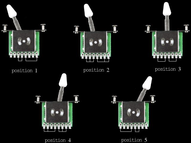 Notice how when the switch lever is all the way to the left the contacts are only made on the far right at the bottom of the switch. As the switch lever moves to the right it makes contact moving right to left on the bottom of the switch. It's the same mistake I made wiring my first guitar...and I doubt I'm the only one who ever did this. Make sense now? Let me know if I missed something, or didn't explain myself clearly enough. Happy Trails Cynical One |
|
tw0409
Apprentice Shielder
Posts: 31
Likes: 0
|
Post by tw0409 on Nov 26, 2011 13:47:20 GMT -5
Thanks for the explanation.... but I am still confused about why is it position 1 and 2 but not position 4 and 5. This may be the reason...I find myself referring to this diagram you post earlier...   ......AND WOW... I am stunned that you could have so many different variations in tone. Form crisp to fat and dark to bright, looks like you've got them all covered. |
|
|
|
Post by cynical1 on Nov 26, 2011 14:52:58 GMT -5
Thanks for the explanation.... but I am still confused about why is it position 1 and 2 but not position 4 and 5. This may be the reason...I find myself referring to this diagram you post earlier... Don't let the position names confuse you. They're really only helpful when making sure you keep your ducks in a row. A lot of guitar wiring seems counter-intuitive when starting out. Learn them the right way starting out and it'll all make sense in time. Plus, we still need someone to drop by and sign of on my drawing, too. And for the price of two more holes you can have them all as well. One thing not on that drawing was a change I made to the Free Woman Tone mod. I swapped the .047 and .022 caps out for a .082 and .056 caps for a .033 cap value in the middle. But I like darker sounding guitars... Happy Trails Cynical One |
|
|
|
Post by newey on Nov 26, 2011 19:46:08 GMT -5
I'll give cyn's drawing my blessing, at least to the extent that it accurately reflects my schematic.
Cyn1 said:
This is the only difference between the two diagrams. Cyn1 has the DM red wired to hot (North Start) and the SD black to hot (North Start), I did it the other way around, with the Green (South Start) of all wired to hot.
The pickup will operate exactly the same regardless of which way round it's wired, it matters not at all whether the South coil is wired to hot before the North coil, or vice versa.
Either way is equivalent, again, assuming that DM's South and SD's South are the same. Which they probably are, but no guarantees.
While there is an absolute magnetic polarity in terms of alignment with the Earth's magnetic field, the magnet as mounted to a pickup can be oriented either way- North side up vs. North side down. Fender's coils are opposite of SD's in this way, for example.
and, tw-
The different "look" to the DPDT switches comes about only because cyn's version uses the star grounding, while tw has "daisy-chained" the "not hot" and the "hot" from one switch to the other. Again, either way is electrically equivalent, so long as the "hots" end up attached to "hot" and the "not hots" go to the "not hot" side, and eventually to "ground".
And, tw, we're not trying to confuse you by jettisoning "Ground" and by putting "hot" and "not hot" in quotation marks. Since a guitar circuit is an AC circuit, "ground" has only a relative meaning (until we get out to the amp, anyway).
"hot" and "ground" are DC terms which can be more confusing than useful sometimes, so we try to stay away from these terms when possible.
|
|
tw0409
Apprentice Shielder
Posts: 31
Likes: 0
|
Post by tw0409 on Nov 27, 2011 12:55:04 GMT -5
I am glad that we finally landed on a wiring diagram. I appreciate you! cyn and newey.
Some update...
Yesterday I went to the the hardware shop for some solder and a washer that Cyn mentioned earlier. I could not find a brass or a copper so I picked up an aluminum equivalent. That will work as well as the brass ones right?
Cyn... you mentioned that the star ground should make contact with the shield. Did you mean the shied on the pickguard or the shield on the cavity's wall? The guitar I have now is a cheap squire, which I don't want to waste time to shield. However, once I can earn $$$ I will consider a real strat then I will shield it.
So... given that my cavity is not shielded and the star ground is screw in the cavity, do I need a lead goes from pickguard shield to the star ground?
Some buying suggestion... Now I am pretty much set on the wiring. I will start ordering stuff. Which brand of DPDT pot do you recommend? Alpha? Bourns? or Dimarzio?
|
|
|
|
Post by cynical1 on Nov 27, 2011 13:47:46 GMT -5
I am glad that we finally landed on a wiring diagram. I appreciate you! cyn and newey. Glad we could help. Most of the wiring designs around here fly right past me, but yours was so close to mine that I could actually contribute something to the discussion. Soldering to aluminum is not something you want to spend time and solder on. I'm not sure what part of the world you're in, but here in the US any number of on-line hardware or fastener stores sell copper washers. They scuff up easily and you can solder a cable to them if the mood strikes you. A solid piece of copper, or a small cutoff from some copper tubing or pipe hammered flat and drilled to allow you to screw it into the body may work as well. Let me know where you are in the world and I may be able to scare up a source for you. You can still screw the washer, or fabricated copper piece into the wood body without the shielding. It just keeps everything neatly in place...don't want your ground connections arbitrarily floating around the cavity... Seeing as how you have noiseless humbuckers with no coil splits, the shielding of the cavity is probably not as critical in your case. You can take a piece of aluminum foil if you don't have any copper shielding and just glue it in place from the top of the body so it can make contact with the pickguard shield and run it behind where you are screwing in your star ground piece. Or you can just omit it if that's easier. If you're using push\pulls, which I never use, it's probably going to depend on what on-line source you choose. Alpha is a good OEM quality, Bourns is generally higher end, but you pay for that higher end, and the DiMarzio is somewhere in between. Like I said before, depending on where you are in the world determines where you buy your parts from. In the US I generally use Digi-Key or Mouser for everything. As a side note, Logarithmic, or Log, pots are used for volume and Linear pots are used for tone. I have seen Linear pots used for both. Much of this is personal preference and whatever works for you is fine by me. Hope that helps. Happy Trials Cynical One |
|
tw0409
Apprentice Shielder
Posts: 31
Likes: 0
|
Post by tw0409 on Nov 27, 2011 14:31:40 GMT -5
I live in California... maybe I should go to bigger store like home depot. Anyways, will the solder stick if I scuff up the aluminum washer? How about brass? Will it work better than aluminum?
|
|
|
|
Post by JohnH on Nov 27, 2011 15:06:27 GMT -5
I live in California... maybe I should go to bigger store like home depot. Anyways, will the solder stick if I scuff up the aluminum washer? How about brass? Will it work better than aluminum? I think alumin(i)um inherently does not solder at all, not matter what you do. The solder just doesn't seem to bond with it and the hot solder just sits up like rain drops on a new car. Brass is OK and in fact, I think most normal washers are OK too for soldering to, You can easily test one, just scuff it a bit first and heat it and apply solder to the washer. |
|
|
|
Post by cynical1 on Nov 27, 2011 15:33:47 GMT -5
|
|
tw0409
Apprentice Shielder
Posts: 31
Likes: 0
|
Post by tw0409 on Nov 28, 2011 9:46:41 GMT -5
Cyn,
Thanks for all the nice convenient links. Today I pick up some brass washers. I am pretty sure it will work this time.
oh... another thing I forgot to ask. Do you have any experience with treble bleed circuit? I know there's a good long thread here but I am not sure for my pots and pickups, which value of treble bleed should I use?
|
|


 )
)

 ......AND WOW... I am stunned that you could have so many different variations in tone. Form crisp to fat and dark to bright, looks like you've got them all covered.
