|
|
Post by jewellworks on Jan 27, 2009 23:03:39 GMT -5
hey everybody maybe this is an easy question. ive got a Dean Cadillac. i replaced the pickups with Gibson 490's (T/R). the original pickups were splitable by pulling up on the tone pots. since changing them out, the push/pull's are useless. but it got me to thinking... im a big Frank Zappa fan. and one of the things he used to do was have his tech wire in a switch (or a bunch of switches) that would "emphasize" a certain frequency. -like a wah stuck in the middle. the way i see it Barry, it was a tone cap. the problem im having, is i dont know what values do what. im looking for 2 mid boost caps. i realise a .33 and a .47 are somewhat standard for a tone pot, and i guess i could experiment till i go blind with solder smoke in my eyes, but i guess im looking for a starter point. and if its more complicated than just wiring it in series to ground when i pull up on the switch, then maybe a diagram/explaination would help. 2 dpdt, push pul pots. when down, theyre standard tone pots w/ .47 caps. when up, the bridge has one "tone", the neck has another. and when when combined...  !!!? any ideas? for what its worth, i also have a Torres Varitone kit installed in my 335. the instructions only have mfr part numbers, and not values. but thats the sort of thing im going for. -and if anyone has the actual values, ect for a Torres or Gibson varitone, that would go a long way with my experimenting! thanx nuts! |
|
|
|
Post by newey on Jan 27, 2009 23:24:42 GMT -5
jw- Tone caps are a frequent topic. While this idea of ChrisK's uses a toggle switch, the same philosophy could be adapted to 2 push/pull pots: Free "Woman Tone"EDIT: This thread sort of wanders all over, but has some good info on the subject: Capacitors for Guitars |
|
|
|
Post by pete12345 on Jan 28, 2009 4:24:39 GMT -5
im looking for 2 mid boost caps. A capacitor (or any passive circuit) can't boost a signal. What they do is allow any frequency above a certain value (depending on the value of the capacitor) to pass through, and all others meet with resistance (slightly simplified explanation here, I know) Wired in parallel, high frequencies will be short-circuited across the pickup, with only the lower ones reaching the output (a treble cut). Wired in series, the low frequencies will in effect be blocked by the capacitor, with the higher ones passing through to the output (a bass cut). All you can do is use one capacitor as a treble cut, and another as a bass cut, leaving you with whatever's in the middle. The result might be a bit weak and thin unless you go for some active circuitry. |
|
|
|
Post by jewellworks on Jan 28, 2009 9:24:50 GMT -5
thanx guys. this is exactly what i was looking for. i didnt know a cap in series is a bass cut. that info alone is of great value! ill keep digging around for more info on that subject. i poked around on the "capacitors for guitars" thread, but your right, it rambles...  the "woman tone" diagram is great, and the chart with the cap values, combined, ect... great stuff. you have pointed me in the right direction. thanx a million! ;D |
|
|
|
Post by pete12345 on Jan 28, 2009 9:57:54 GMT -5
If you have two tone controls, you could wire one as a master treble cut, and the other as a master bass cut. Having separate tones for each pickup are only really useful with pickups is series.
|
|
|
|
Post by jewellworks on Jan 28, 2009 10:12:13 GMT -5
so... i would take a parallel feed off the switch, to the first tone pot, with the push pull down, and put a .47 (parallel to ground) and then branch over to the other pot, push pull down, and have a cap in series?? uuuuhhh ...i need a diagram then would i still be able to have my "woman tone" when i pull up on the pots?  yeah... i need a diagram. this sounds like fun...  |
|
|
|
Post by ChrisK on Jan 28, 2009 18:16:02 GMT -5
Who's Barry? Well, in and of itself, no. However, in conjunction with the inductance and resistance of a pickup, the cap (primarily made up of the cable capacitance and the tone cap when the pot is turned down) forms a series LCR circuit which does indeed boost frequencies against the baseline output of the pickup itself. I have posted some articles on this effect; notably Pickup Coil Response Tuning and The Passive High-Cut Tone Control. |
|
|
|
Post by jewellworks on Jan 28, 2009 23:17:01 GMT -5
If you have two tone controls, you could wire one as a master treble cut, and the other as a master bass cut. Having separate tones for each pickup are only really useful with pickups is series. so... seriously... a diagram anyone? or just 'splain it to me. and since ive never even thought about a bass cut cap, gimme a starter value for the cap. -please. ;D ive tried going through the Capacitors For Guitars thread, but really... its 6 pages deep, and rambly... if you were a Frank Zappa freak like me, youd know what i was referencing.  |
|
|
|
Post by cynical1 on Jan 28, 2009 23:40:22 GMT -5
if you were a Frank Zappa freak like me, youd know what i was referencing. My guess is Barry Miles. He wrote a book or two about Zappa, as I recall. I have one of them. Not too bad. He writes in the rock and counter-culture genre. Do I win anything? Happy Trails Cynical One |
|
|
|
Post by ashcatlt on Jan 29, 2009 0:02:04 GMT -5
I'm afraid I'm not completely clear what you're looking for with the switches. It's my understanding that the "woman tone" thing is a way to switch between three cap values on the standard low-pass tone control. Anyway, this is a schematic that includes a normal tone control and a hi-pass (bass-cut). The volume/tone section is independent of the pickup switching, and could easily be snipped out and jammed into any "master" scheme you want. It doesn't include any switching, but we can find a way to work those in. Note that this also includes the "treble bleed cap" C2 across the volume pot, which is not necessary for the function of either of the tone controls. That schematic keeps popping up, but I don't recall anybody ever saying how well it works. A (relatively) long time ago there was a thread where I thought it was decided we could get much more satisfying bass-cut by grounding one of the lugs on the hi-pass pot, pretty much exactly like the treble bleed mod. What happened with that? |
|
|
|
Post by jewellworks on Jan 29, 2009 12:48:06 GMT -5
if you were a Frank Zappa freak like me, youd know what i was referencing. My guess is Barry Miles. He wrote a book or two about Zappa, as I recall. I have one of them. Not too bad. He writes in the rock and counter-culture genre. Do I win anything? Happy Trails Cynical One thats a very good guess... but... no. i was refering to the very opening line to Lumpy Gravy "the way i see it Barry... this should be a very DINAMITE show" as for the master bass cut and trebble cut, im sure i can handle it from here. and ill figgure something out for the pull up position for the pots. even if its a straight cap, and no "pot" action... ive got pleanty to go on. thanx guys |
|
|
|
Post by ChrisK on Jan 29, 2009 13:51:23 GMT -5
tedfixx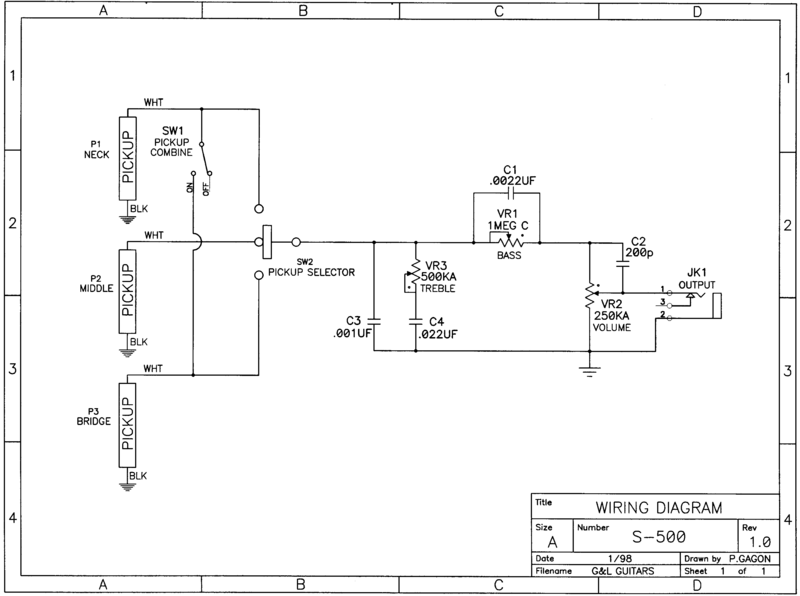
|
|
|
|
Post by jewellworks on Jan 29, 2009 15:56:56 GMT -5
this looks alot like the schematic that ashcatlt posted, but with a much simplified switch. but this also has an additional cap. am i reading this right, that C3 and C4 (a .001uf and a .022) are in parelell to eachother, then fed in series to the trebble pot? and the bass pot is wired "stock", like any other tone pot, but with the cap value at .0022uf. and how critical is the listed value of the tone pots? the trebble is listed as 500ka, and the bass is 1M?! id rather not swap out my tone pots. they both are push pull, 500ka's. the guitar is a 2 humbucker guitar, and not a strat, like this diagram. but im sure it will put me on the right path. now... i need to draw this out in "guitar guts", as schematics confuse me. i need to transfer this to real wires, lugs and pot terminals, as seen from the control cavity. thats my problem. please dont anybody worry about it. you all have been very VERY helpful! ;D |
|
|
|
Post by ashcatlt on Jan 29, 2009 17:02:57 GMT -5
No, the treble pot is wired as normal, in parallel to the output, with the cap to ground. This one has another cap in parallel with it to ground. It should give some minimum amount of low-pass action even when the tone pot is turned to max. Not sure how it actually plays out without a more thorough analysis.
The bass-cut is in series with the hot output, with the cap parallel to it. Basically (as in extremely over simplified), higher frequencies will find it easier to pass through the cap than the resistance offered by the pot. Lower frequencies will find it easier to go through the pot, but will tend to drop some voltage in the process.
|
|
|
|
Post by jewellworks on Jan 29, 2009 17:30:39 GMT -5
It should give some minimum amount of low-pass action even when the tone pot is turned to max. do you mean HI-PASS? this is a low CUT / Hi Pass filter. im glad i asked if i was reading that right. i clearly wasnt. so i wire the "trebble" -hi-pass/low-cut- pot, "stock", but with an additional .001 cap in parallel, from hot (from the switch), to ground (the top of the pot, where all the ground leads are). and then for the "bass" -low-pass/hi-cut- pot, i straddle a .0022uf across the "in" and "middle" lugs. that sounds alot like the trebble bleed circuit. this looks backwards to me... now im confused... |
|
|
|
Post by ChrisK on Jan 29, 2009 19:13:00 GMT -5
Sure you do, it's called Pickup Coil Response Tuning. It tunes the peaking frequency of the passive series LCR circuit lower. Also refer to Helmuth E. W. Lemme for his most excellent explanation The Secrets of Electrical Guitar Pickups of this along with his general pickup technical explanation. That's because the one that ashcatlt posted is one of my designs with a tone control section based on the G&L S-500 guitar. I chose to post the G&L design schematic to avoid the complexity of the dual 4-way switch Tele design. Your terminology is confused. VR3 and C4 is a treble cut circuit, like most tone controls in an electric guitar. It is a high-pass to signal ground circuit, passing the highs to ground more as the resistance is decreased, thus removing them more from the signal. VR1 and C1 is a bass cut circuit. It is a high-pass to signal output circuit, blocking the lows to the output more as the resistance is increased. VR2 and C2 is a volume pot with a high-pass filter to the output. As the volume is turned down, the higher frequencies are allowed to bypass the pot to the output. This helps since the human ear's response is not only frequency based, but frequency as a function of relative volume based (why stereo's have loudness controls). C3 is a peaking cap used to alter the pickup's bandpass frequency. It, along with the cable capacitance, are the "C" in the series LCR circuit. The "R" is the pickup(s) effective DC resistance and the "L" is the pickup(s) effective inductance. See the two links posted above. Bear in mind that the pass and blocking functions are not binary on and off, or yes and no, functions, but slopes of increasing impedance as a function of frequency. The impedance of a high-pass network decreases with higher frequencies and the impedance of a low-pass network increases with higher frequencies. The actual effect of a pass network is a function of whether it's in series with the signal path or in parallel with the signal generator. |
|
|
|
Post by ashcatlt on Jan 29, 2009 23:37:49 GMT -5
Okay, I knew that part. I don't know enough about the rest of the circuit (particularly the pickups) to speculate on the specific outcome. It passes hi frequencies to ground, cut's treble to output, and passes low frequencies to output. It's a low-pass filter. Just to (hopefully) clear up a little more. |
|
|
|
Post by jewellworks on Feb 4, 2009 11:05:22 GMT -5
that explains it better. when it says trebble, its not the trebble control, but the cut. i DID have it backwards. -its all good now. -at least as far as what does what. BUT, i started going through this last night, transfering the schematic to "guitar guts" and actual "wires and lugs". im also having to convert this schematic for a strat, to a 2HB LP style. for the most part, i got it figgured out. but im totaly lost on the series wiring of the bass cut pot. the trebble cut is pretty much a standard tone pot, with one side to ground. but im lost on the series wiring. its "in line" with the "hot" signal comming from the switch, rather than a "sidechain", like a regular tone pot. having never wired in series, i dont understand what lugs to wire too, where the cap goes exactly... ive been to the guitarnuts page that shows the schematic and pot, and how what is what, but im still not getting it.  it looks like the cap ( C1 = .0022uf) is straddled across the two outer lugs, with the wiper/middle lug tied to the "high" end lug, and the signal/hot wire comes to the "high" AND middle, and out the "low" end, to the jack. and another thing.... im also looking at the "Woman Tone" diagram by Chrisk... correct me if im wong, but the woman tone is a .015uf cap? wired to ground like a standard tone pot? -that would be a mid-peak. -or at least, not as much of a roll off on the highs as a .022, or .033, ect...  sorry im so lost... |
|
|
|
Post by ashcatlt on Feb 4, 2009 13:35:07 GMT -5
it looks like the cap ( C1 = .0022uf) is straddled across the two outer lugs, with the wiper/middle lug tied to the "high" end lug, and the signal/hot wire comes to the "high" AND middle, and out the "low" end, to the jack. I think you've got it right. It should roll off more highs than the others.Edit - never mind. |
|
|
|
Post by ChrisK on Feb 4, 2009 14:48:02 GMT -5
The lower the capacitance value, the higher the roll-off frequency, the less the high frequency roll-off. The lower the capacitance, the higher the capacitive reactance at any given frequency, the less the attenuation. Xc = 1/(2 * Pi * Freq * Farads) The 0.015uF has the highest reactance (and this is a virtual capacitor value in that in my design, it's really a 0.047uF cap in series with a 0.22uF cap). The 0.022uF is lower and the 0.047uF is the lowest. In this graph from The Passive High-Cut Tone Control, one can see this relationship.  |
|
|
|
Post by jewellworks on Feb 4, 2009 16:59:37 GMT -5
heres what i came up with: 2 Humbuckers, 2 DPDT push pull pots on the tone pots both pots DOWN = High Cut and Low Cut "low cut/neck tone" pot UP = NO TONE LOAD. total bypass of the tone circuit "hi cut/bridge tone" pot UP = "woman tone" mid peak, hard wired. no variable tone pot control. i have another version where i switch between the .022 and the .015 caps, and retain the full use of the variable tone control. youll note that i have a .001 trebble bleed cap on the neck HB only. i dont mind a little high end loss when in back down on the bridge vol pot. i didnt install the .001 (C3) bandpass cap shown on Chrisk's dwg either. if i really need too, ill go back and strap it on the "hi cut/bridge tone" pot middle lug, to ground. its a quick install. i think this'll work. ;D 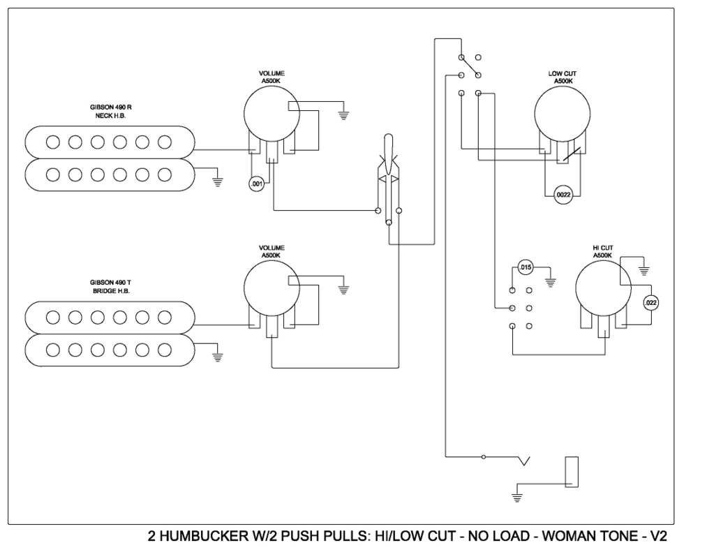 |
|
|
|
Post by jewellworks on Feb 5, 2009 9:52:10 GMT -5
ok... heres my report: last night, i wired this up exactly as seen above. with one exception: the push pulls in this dwg are actualy upside down. so ill fix that on the next dwg. otherwise, its wired as-is. that said, the bass and trebble cut controls work as designed. the only thing that concerns me about this design is the bass cut. i just barely turn the pot control and the lows are cut. theres really no "taper" at all. it acts more like an on/off switch.  i have the Total Tone Circuit Bypass on the Low Cut push pull. it works, but im surprised it didnt really do anything to the overall sound. i thought that by taking the load off, id get a tad more output, or highs, or something. but nothing really happened. so im Nixxing that on the re-design, and putting that switch to better use. and another thing that doesnt work like i thought it would is the push pull with the .015 cap directly to ground. i thought it would give me a mid-peak. but instead it cuts a TON of high end. it gives a VERY muted tone. great for clean jazz tones, but not what i was expecting, or wanting. reading the chart posted by ChrisK, i was expecting the .015 cap to have a peak of around 6db, at 800hz or so. not a massive roll-off of the highs. obviously, im doing something wrong. so, for me, its back to the drawing board, and back to the original topic of this post. what to do with the push pulls? so to summerise my desires: im looking for 2 different mid peak tones when i pull up on the switches. preferably a "global" peak, no matter which pickup is selected. even if theyre hard wired and i get no pot control, that'd be fine with me. SO... both down i get a bass and trebble cut tone control. (after i figgure out how to get more "taper" for the bass cut, and not just an on/off effect) pull one up i get a mid peak at "X" frequency, and a tone control on the other pot. -say, the trebble cut... push "X" back down, and pull up on the other, and i get a different mid peak at "Y" frequency, and a tone control on the other pot. -the bass cut pot... pull both up, and i get a combination on the "X & Y" = "Z" mid peak, with no tone control. any ideas? and like i mentioned in the original post... i have a Torres Engineering Varitone kit that i made and installed in my ES 335. which does exactly what im looking for on the first 2 tones. but the caps have a manufacturer number, and not a "value", so i dont know what caps they actually are. and he also has some sort of inductor or small transformer on it as well. maybe thats the key. i have no idea. if anyone has a schematic or diagram for a gibson varitone switch, that might go a long way to figuring out what i need to make this work. -yes, i "could" just stick a varitone in this and be done with it, but i really want a stock look. if what im desiring isnt possible without drilling extra holes for more switches or whatever, then ill get a varitone. but id like to try it my way first... again... any ideas? |
|
|
|
Post by ashcatlt on Feb 5, 2009 14:37:12 GMT -5
that said, the bass and trebble cut controls work as designed. the only thing that concerns me about this design is the bass cut. i just barely turn the pot control and the lows are cut. theres really no "taper" at all. it acts more like an on/off switch. I think this is why there's a 1M pot specified in the schematics we posted. Before you go buy a new pot, though, try reversing the input and output leads. This will reverse the taper. It might feel a little funny to turn the knob the "wrong" way, but it also might help get a smoother transition. The no-load thing will be a very subtle effect. Most likely it will cause a slight increase of the resonant peak at the very highest frequencies (around 4-6KHz). Flipping that switch does the exact same thing as turning a standard hi-cut tone (with a .015 cap) control down to 0. First, lets make sure you're using the proper "denomination", that it is in fact .015 u. I have to say I never understood why you keep calling this a mid-peak. The mid-peak, or bandpass, comes when you combine the hi-pass filter with the lo-pass. You'll only be letting through the frequencies that fall between the two cutoff points. If everything works out correctly, you might also get some resonance, or boost in this band. |
|
|
|
Post by jewellworks on Feb 5, 2009 15:34:01 GMT -5
i guess i keep saying this because thats what im wanting. not so much that its what im getting. in other words... it makes sence that ill need 2 caps. one in series with the signal for low end roll-off, and another paralell to ground for high end roll off. bandpass = mid peak. i guess... BUT, i keep going back to the Varitone switch i put in my 335. its a very simple design with 5 caps, one lead in, one lead out through an inductor, or a transformer looking thing, to ground. its parallel to the volume control, like most tone controls are. there isnt anything terribly bizzare looking or overtly fancy. one cap, = mid peak with some highs rolled off. another cap = bigger mid peak with more highs rolled off, another cap= bass peak with lots of highs rolled off, another cap=huge bass boost with tons of highs rolled off. and the last cap is a mid scoop. almost sounds like a piezo pickup in an accoustic. in & out. turn the knob, done. cant i do something like that on this guitar with 2 push pulls? maybe the key is the inductor or whatever... but i cant seem to find any info on the veritone. how it works, what the cap values are... nuthin. i would LOVE to get the same mid boost i get with position 1 of the varitone with push pull #1. and pos 2 of the varitone with the other push pull. both up? who knows? maybe itll sound terrible. maybe ill blow a speaker... ?? im looking for that kind of thing. FZ had these switches on his guitars that would do just that, and im ASSUMING they were caps. maybe its alot more than that. -dunno. |
|
|
|
Post by ChrisK on Feb 5, 2009 16:01:45 GMT -5
If you look at my graph posted earlier in this thread, you'll see that there is indeed peaking at around 700 - 800 Hz from the 0.015 uF cap USING THE COMPONENT VALUES AND SIMULATION PARAMETERS SPECIFIED IN THE MODEL IN THE REFERENCED POST (I don't know what's in your guitar). This is IN LIEU of the peaking shown under the curve labeled "all at 250K" (i.e. minimal capacitor effect). It is not the case that peaking will occur when there was none, the peaking is shifted lower in frequency as a function of the additional parallel capacitance. If you look at the "all at 250K" curve vs the 0.015uF curve, the area between the two (to the right of the 0.015uF curve and to the left of the "all at 250K" curve) is gone. If you shift the peaking two octaves lower (3,200 Hz to 800 Hz), it will sound more muted and jazzier. I'm presuming from your diagram that you turn the pot down (counter-clockwise) to cut the lows. The high-pass pot in the G&L schematic is indicated to be a 1 Meg "C" pot. This is a reverse (left-hand) audio taper pot. If you are using a 500K right-hand audio taper pot, it will behave very similar to a 1 Meg linear taper pot from "10" down to "5". From "10" to "9" you already have 100K across the cap. Rewire it so that you turn it up (clockwise) to enhance the highs (cut the lows). this way, you will have the audio taper going in the correct direction. Well, post the info, I can read manufacturer's part numbers. You bet. Search a'web for, uh, "varitone schematic". The varitone is a notch (anti-peak) filter. ashcatlt is correct; make sure that the cap values that you're using are really the cap values that you want to use. A 0.15uF cap is indeed much muddier than a 0.015 uF cap. This is a mid- pass effect from the RC components. R and C (charge storage) components will not cause a boost. The boost, or peaking, comes from the inductance (energy storage) of the coil in series with its internal generator, driving a load that is a parallel capacitance to signal common (the series LCR circuit). The only effect that the pickup DC resistance has is to reduce the quality (Q) of the circuit and broaden the peak and dampen its level. |
|
|
|
Post by jewellworks on Feb 5, 2009 16:24:47 GMT -5
hows this for a hard wired band pass, on a push pull, with a normal tone control when pushed down? all i need is the cap values. -right? 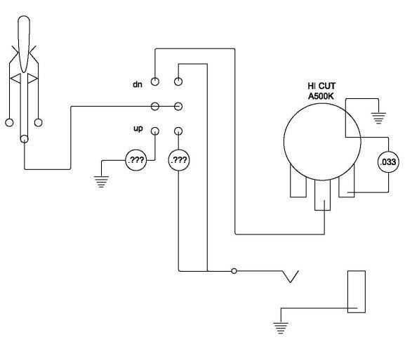 that was a typo on my part. i was very careful to get the correct value caps. BTW: i googled Varitone Schematic and found some cap values, as built into the Gibson Blueshawk: .001uf, .003uf, .01uf, .03uf, .22uf through a 7.2h inductor to ground. the Gibson Blueshawk diagram also shows a 10M reisitor in series to each cap. and 100k to the whole network. i know the Torres Varitone was just a bunch of caps and an inductor. no resistors. hhhmmm www.blueshawk.info/official_gibson_schematic.htmi also read at another site that someone said the value of the inductor was 1.5H. -does that make sence? seems like a big difference to me, from 7.2 to 1.5... so ... what do i do now? |
|
|
|
Post by ChrisK on Feb 5, 2009 19:42:04 GMT -5
The 10 Meg resistor are to help the caps be at the proper charge level such that there will be no loud "pop" when one is selected. Any cap selected in circuit will have an instantaneous charge as a function of the instantaneous DC level of the AC signal left on it when the cap is disconnected (i.e. another position is selected).
Better quality caps have little leakage and hence will keep the charge level longer. If the instantaneous level of the AC signal is different (suppose that the old charge level was fully positive when disconnected and the new instantaneous signal level is fully negative), a loud "pop" or click will occur since the signal will be driven with essentially the leading edge of a square wave.
Yeah, there's a bit of ambiguity on this. The frequency difference is actually a function of the square root of the value difference. In this case, it's a little over an octave (2.19 times).
Capacitors come in common value increments over many ranges. For any given range, for +/-20% values, one can get 10, 15, 22, 33 ,47, and 68. These are the significant figures. There is also a range multiplier, for this type of cap it's in pF (picoFarads). A 1.0 uF (105), 0.1 uF (104), 0.01 uF (103), 0.001 uF (102) and etc are all commonly available.
When one mentions an excessive capacitance effect, it's the first thing that we try to verify.
Based on your experience with the 0.015 uF directly in parallel, I would not combine this with the bass cut circuit since the highs are already fairly well attenuated.
|
|
|
|
Post by jewellworks on Feb 6, 2009 10:51:53 GMT -5
So.... It looks like what I'm really wanting is the first two tones of my Varitone switch, one each, to my push/pull switches. That will give me exactly the "Mid-Boost" I've been talking about. Even though, when looking at the specs on the schematic, its actually a notch filter, cutting at a certain frequency. Not knowing any better, the overall effect to my ears is a Mid-Boost. I understand that now. -And I understand the confusion it caused among you. My ignorance on all this was thinking all i needed was just a simple capacitor, at "such n such" a value, wired to ground. -Like any other capicitor. -Wrong! -And that the "Woman Tone" was a single emphasised frequency. -Not so... My appologies for my ignorance. But thats why Im here. -To show off how dumb I am in front of all you know-it-all's. It seems that all the info I need for my project is on the Gibson Blueshawk Schematic. I should be able to install a 10M resistor in series with a .001uf cap, to the "up" side of one of the push/pull switches, through it, and out through a 7.4H inductor, to ground. And for the other push/pull switch, exactly the same thing, only use a .003uf cap instead. Can I share the inductor? Or do i need to buy 2? One each? Im affraid to ask what an inductor really IS and what it DOES. How about where to buy one? Stew-Mac? Ebay? I refuse to buy anything ar Radio Shack. Thanks to everyone for all your help and for your paitience with me. I actually learned a thing or two durring this process. |
|
|
|
Post by jewellworks on Feb 6, 2009 11:12:59 GMT -5
I buy all my components at a local electronics surplus store. Its ENORMOUS, and generally speaking, if they dont have it, it doesnt exist. -Not litterealy true, but close. As an inexperienced electronics buyer, all I can do for the most part, is go to the bin and grab a few of whatever is written on the outside of the bin. If the diagram calls for a .015uf, or a .0022uf, I hope that whats labled for that bin, is really what im taking out of it. I have run into some instances where resistors were in the wrong bin. I can read the resistor color code. That 3rd color really makes a big difference! I understand the tollerances code, as they have a chart on the wall at the store. J=5%, K=10%, L=20%, and M=+80%/-20% -which looks like a huge variance to me. I try and get the caps that are marked "J". -Or better yet, say 1% right on them. The .015uf cap I bought says 154J. If thats really NOT a .015uf, then what is it? 102J should be .001uf (which is 1pf, right?) 222J is .0022uf (?), (which is 2pf, right?) -or is it 200pf? the Bass/Trebble cut curcuit has a .0022uf for the bass cut, (C1) but a 200p for the trebble bleed (C2). -arnt these the same value? Im guessing all this info is over at the Capicitors For Guitars thread. |
|
|
|
Post by ChrisK on Feb 6, 2009 20:31:40 GMT -5
Now that we're getting into the details of parts, I need to know what corner of the Globe it is that you're located. MM World can mean Florida, California, or France! I ask since I don't want to give a source for parts that might be in the wrong corner. Aha! It's good that we had this latest conversation. 15 4J is a 15 0000 pF cap. That is 150,000 pF or 0.15uF. That's a very large woman tone. I'll bet that she has a frightening voice. This would explain the excessive filtering effect. A 0.015 uF cap (also called 15 nF) is 153J. 102J is 10 00 pF (1,000 pF) or 1 nF or 0.001 uF 222J is 22 00 pF (2,200 pF) or 2.2 nF or 0.0022 u 200pF would be a 221J uF = 10 -6 Farads nF = 10 -9 Farads pF = 10 -12 Farads This is the tolerance for a Z5U dielectric ceramic cap that's only suitable for power rail filtering. I'm not being a tone snob, but I never use ceramic caps for any audio signal applications. There are too many other, better types out there for not a significant amount of coin. I like polypropylene. As well you should be. The truth involves electrical engineering. A capacitor stores an electrical charge. It's like a really little rechargeable battery. A 1 F cap discharged at a rate of 1 Amp per second will have its charge voltage level drop 1 Volt per second. A 0.015 uF cap is 0.000 000 015 Farads. (It's a tiny rechargeable battery.) An inductor is an energy storage device. It stores energy in its magnetic field when a current passes thru it. When the current stops, the field collapses, forcing current to continue thru it until the field has completely collapsed. This is how an automobile ignition system works. So, what does this mean to guitar wiring? Well, a capacitor and an inductor are corollaries to each other. The capacitors impedance (capacitive reactance Xc = 1/[2*Pi*F*C]) decreases as the frequency increases. We've discussed this earlier in this thread in that a capacitor is inherently a high pass element in that respect. A capacitor in series with a signal results in a high pass response, a capacitor across a signal to ground is a high pass to ground and a low pass response results. An inductor's impedance (inductive reactance Xl = 2*Pi*F*L) increases as the frequency increases. It is inherently a low pass element. An inductor in series with a signal results in a low pass response, an inductor across a signal to ground is a low pass to ground and a high pass response results. Now, these are not step functions but slopes. Each time that the frequency of interest doubles, the capacitive reactance halves and the inductive reactance doubles. The Varitone is a series LC circuit of a cap and inductor across a signal to ground. It performs a notch filtering response with the center frequency occurring when the capacitive and inductive reactances are equal. Of course, if it were in series with the signal output, a band pass response would result. And conversely, if a parallel LC circuit was across a signal output to ground, a band pass response would result, and if this was in series with the signal output, a notch response would result. Inductors are expensive and hard to find. Fortunately, small interstage signal coupling transformers are not. A transformer is an inductor with more than one winding. This is what Torres uses (methinks). I do know of some U.S. suppliers of these. They tend to be around $2 to $4. |
|


 !!!?
!!!?