|
|
Post by sumgai on Aug 14, 2006 15:24:28 GMT -5
Hooooookaaaayyy! I've decided to declare that Red is my favorite color, as in redfaced.  EDIT EDIT While not so much a "flaw", I've made a design revision, based on unklmickey's questions below. See Reply #34 for a revised, and hopefully more useful, diagram. Plus, there are now several partial diagrams that show the signal paths for Off, Parallel and Series. </edit> Some very obvious mistakes show in my previous drawing, which I've left intact as an object lesson to one and all, but mostly to myself - to jump the gun without thinking is to get it wrong. 'Nuff said. All new, drawn up from scratch, here's RanchTooth, Version 2:  What's changed? Rather ask, what's not changed.  For starters, I had the niggling suspicion that I had been thinking inside the box (again), so I looked at the S/P switches for awhile, and decided that I could make my move here. And indeed I did. This let me go back to a "normal" phase reversal switch configuration. All of that allowed me to remove the all-too-obvious short from my earlier version; and to complete the reverse-phase circuit connection that I had left open (on each switch). The only thing left "unfixed" is what some call the hanging-hot problem. Since I don't see this as a problem (at least, not in my guitar), I've chosen to leave it as is. If someone else want's to dope out a cure for it, then by all means, be my guest.  The switch I've shown is the same as described above. In looking around the parts houses' web sites, I see way, way too many items to wade through, so I'm not gonna be able to give anyone an exact part number at some particular supply house. (Sorry 'bout that.) The only requirement for this kind of switch is that the center position be an actual throw, and not a "center-off" handle position. As evident from the drawing, there must be 4 terminals or lugs in order for this to work. John, yes indeed, slide switches can be flimsy, but you should recall that beaucoup early Fender "student" model guitars are still extant, and I'd hazard a guess that the great majority of them still have their original switches, operating just fine. (Well, perhaps they'd benefit from a cleaning job. ) unk, you asserted I'd disagree, partially. Let's number the pups 1 thru 4, left to right. If 1 is in parallel with 2, then that combo will remain in force, no matter how 3 or 4 are switched into the circuit (or left out of it). And if we put 1 and 2 in series, then put that in parallel with 3, then put that trio in series with 4, what do we see? A real mish-mash, I'm sure. I'd have to resort to my abacus to see the resultant calculations of inductances, capacitances, etc. Might be fun, someday when I'm driving my train. ;D But still and all, do we have every possible combination covered here? Seems very likely to me, but I figure that ranchtooth should be the one to conjure up a truth table!  sumgai |
|
|
|
Post by UnklMickey on Aug 14, 2006 16:40:40 GMT -5
...unk, you asserted
I'd disagree, partially. Let's number the pups 1 thru 4, left to right. If 1 is in parallel with 2, then that combo will remain in force, no matter how 3 or 4 are switched into the circuit (or left out of it).... fifty lashes with a wet noodle for me! poor wording. let's see if this will fly: the leftmost pickup is "at the mercy" of whatever configuration is selected to the right.
it must ALWAYS be in series, with any pickups to the right that are in series. i believe this statement will actually be true for any pickup. of course, there are many pickups to the right of #1, and none to the right of #4. unk |
|
|
|
Post by UnklMickey on Aug 14, 2006 18:06:18 GMT -5
Sumgai,
maybe i'm missing something here, but......................
how can you properly control 4 pickups with only 3 switches?
i understand that a S / off / P switch wouldn't make sense for #1.
but doesn't it still require at least an on / off ?
EDIT:
also, i'm having trouble figuring this circuit out.
if it wouldn't be too much trouble, could you make a copy of the drawing, and add red lines to indicate the internal connections of the S/off/P switches?
set one switch to series, another to off, yet another to parallel?
thanks,
unk
|
|
|
|
Post by sumgai on Aug 14, 2006 22:16:53 GMT -5
unk,
Well, as we'll see, I'll have to use a freakin' small noodle with which to administer those lashes!
I wondered about that myself. But I also remember catching a bit of flak for the last circuit I submitted that had an 'all off' position. I guess that some like it, and some don't.
The problem here is, it is indeed now a situation where pup #1 is always on, no matter what. That is best rectified by "exchanging" #1's phase switch for a selector switch, to be wired as the other three are.
I'll get to work on posting some signal path breakout diagrams, give me a few moments.........
Nope, that's simply not true. But as you've pointed out, I've neglected to include any signal path diagrams, making it mighty hard to follow what's going on. Like I said, I'll get busy on that right away.
sumgai
|
|
|
|
Post by sumgai on Aug 15, 2006 1:26:32 GMT -5
And I'm back! ;D Let's start out with a revised drawing of ranchtooth's monstrosity, sporting a new On/Off control of pup #1:  What I'll post next are three different diagrams that I hope will illustrate, generically, the signal path through each selector switch. The red and blue lines can be overlaid onto each of the other switches at any time, thus letting you "mix and match" combos. The red lines are "hot" signal (following a wire), and the blue lines show the signal path inside of the switch, as it sits in that position. Here's the generic Off, or Bypass position (the switch rests in the middle position, or throw):  When Parallel is selected, we also see magenta for the ground side of the pickup:  Series is more complicated, but it starts making a weird kind of sense, after you stare at it long enough:  Discussion: Discussion:This all works, but there is one gotcha: The lowest number pup you activate must be engaged in the Parallel position. Using the diagram to trace the signal path, you'll see that if pup #1 is not already turned on, then activating any of the remaining pup's in series will accomplish nothing - the signal path is incomplete, due to there being no connection to ground at any point along the line. If pup #1's switch were wired to make this possible, then any other pups that are set to either bypass or parallel will instantly cause the whole signal chain to short straight to ground! I feel that this "restriction" is a small price to pay for simplicity. I'd be a fool if I said that we're stuck with this, that there was no way to surmount this problem..... but I'm not gonna knock myself out trying to make it so! ;D More discussion:The SPST switch shown for pup #1 was selected for simplicity. If one wishes to add phase reversal, that can certainly be done, but I didn't think it was necessary. If anyone asks for it, I'll be happy to add it to my current diagram, so that it all looks the same.  Also, specifying this pup as being series or parallel is a non-sequitur. Something has to be the end of the chain, so to speak. If we tried to make it selectable as series or parallel, then we'd create an endless loop that would easily escape any logical analysis...... just ask Hastings! And finally, whether pup #1 is the Neck or the Bridge is immaterial..... make yer choice, and go for the gusto! ;D OK, any questions? sumgai |
|
|
|
Post by ajent__smith on Aug 15, 2006 2:38:38 GMT -5
I think that you should put 4 motherbuckers in there, because why have 8 coils when you can have 16 ? ;D Then, if you put them all in series, the output would be so loud that you wouldn't even need an amp, you could just plug it straight into a 4x12 |
|
|
|
Post by UnklMickey on Aug 15, 2006 11:15:34 GMT -5
Ajent_Smith! you're thinking like a drummer! (sorry i couldn't resist)
2 of the pickups he mentioned are SC sized HBs.
i seriously doubt he'll have enough real estate to fit 4 full HB sized pickups in there.
unk
|
|
|
|
Post by ranchtooth on Aug 15, 2006 11:34:03 GMT -5
By the Beard of Zeus, you guys are wiring gods! Sumgai makes Leo Fender's electronics look like they were designed by a team of mongoloids. So far on my axe I've designed and roughed out the body on the band saw, and routed the neck pocket.  As you can see, the pickups just fit with less than a 3/16" space between them... next project I'm gonna have to go to a longer scale to fit more! Today I think I shall route the pickup and control cavities, place the bridge, bolt on the neck and set in the string ferrules. Woooooooo! |
|
|
|
Post by UnklMickey on Aug 15, 2006 11:38:35 GMT -5
... Nope, that's simply not true. But as you've pointed out, I've neglected to include any signal path diagrams, making it mighty hard to follow what's going on. Like I said, I'll get busy on that right away. sumgai first, thanks for drawing the paths. i wasn't certain how the innards of the switches worked, now i know. i still think my statement is true. regardless of it's s/p switch selection, how can any pickup be in parallel with a pickup to the right that is selected as series? back to other matters, the reason i suggested an on/off for #1. i don't particularly like an all-off possibility, but i think one is needed in this case. what would be more aggregious, would be to have #1 stuck on all the time. it looked like that would happen with your previous version. unk |
|
|
|
Post by ChrisK on Aug 15, 2006 12:07:31 GMT -5
Yeah, brutally mellow! It would like drive the amp out of a window or sumpthin'. While looking at that guitar, all that I can say is "Tesla lives" (not the rock group). There are DP4T slide switches; rocky.digikey.com/WebLib/CW%20Industries/Web%20photos/G-141S-3011.jpgrocky.digikey.com/WebLib/CW%20Industries/Web%20Data/G1138.pdfThere is also a 4P3T; rocky.digikey.com/WebLib/CW%20Industries/Web%20photos/G-660S-6010.jpgI have several of them as I'd considered a retro guitar design with big multi-position slides and chicken headed knobs. The DP4T easily enables series/parallel/north/south coil selection for a humbucker. If one treats every two coils as a pair (such as the bridge humbucker and the middle and neck on an HSS guitar) one can easily have series/parallel/north/south on the bridge humbucker and middle*neck/middle+neck/middle/neck for the two single coils. Adding a third DP4T enables B*MN/B+MN/B/MN fer all the combos. Toss gently and season with phase switches to taste! I've been "NOT" working on a three humbucker guitar for some years now. This is the body, a book-matched chambered Strat copy; 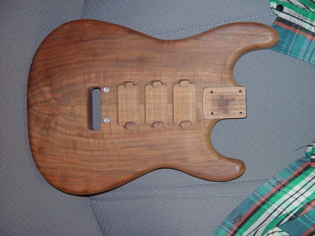 I had developed a wiring scheme in a notebook (it ain't CAD'ified) that focused on multiple coil pairs. It was inspired by a 4 pickup single coil ?VOX? guitar that I had in the 60's. Assuming that the pickups had the same magnetic polarity (for instance, the bridge-facing coil on each was north), one could rotate thru combinations such as this: 1. Bn*Bs 2. Bs*Mn 3. Mn*Ms 4. Ms*Nn 5. Nn*Ns 6. Ns*Bn An additional switch selected series//parallel for each pairing and also single coil. It had a skip switch that shifted the coil paring like this: 1. Bn*Ms (wider pickup window) 2. Bs*Nn (Tele-like) 3. Mn*Ns (wider pickup window) 4. Ms*Bn (redundant) 5. Nn*Bs (redundant) 6. Ns*Mn (redundant) This was to be a DiMarzio-focused guitar. This is a four humbucker (8 coil) guitar if'n I use the DiMarzio Multibucker (a Fast Track and a Chopper?) in the bridge (I have one that I converted to 8 wire). I was planning to use the DiMarzio Tone Zone F in the bridge, the PAF Pro F in the middle, and the Air Norton in the neck. I also have a FRED F, a Steve's Special and another PAF Pro F, so I will use what gives the best tone in an all-walnut chambered body. I chose to use a 6 position rotary switch, a XPDT ON-ON-ON ([X/2]P3T) switch for the series//parallel//single coil, and a many pole DT rotary for the wider spacing mode. I'd stayed away from multiple humbuckers in series 'cuz it'd be like brutally mellow or sumpthin'. I stayed away from the huge switch bank 'cuz I feared an aneurysm. I might finish this someday, but I am often...... Oooh, shiny. |
|
|
|
Post by UnklMickey on Aug 15, 2006 12:28:35 GMT -5
"brutally mellow!" Chris, i think you may have just coined the phrase-of-the-month. unk |
|
|
|
Post by sumgai on Aug 15, 2006 18:38:23 GMT -5
ranchtooth, Well, I don't know if I'd go that far, but I do know that if you look carefully here, you'll have a better understanding of how all this comes about! ;D sumgai |
|
|
|
Post by sumgai on Aug 15, 2006 19:23:59 GMT -5
unk, As per my "discussion", the fact that a position is labeled as "Parallel" is of no significance for the left-most activated pickup. In such cases, the label is a misnomer - we are merely activating the pickup, and since we can't do that via the series position (for reasons already covered), we must use the parallel position. At this point, we need to turn on at least one other pup in order to have either a series or a parallel connection, right? So that other pup's selector will determine the connection type, and that's all we need to know. Or so I should think, anyway. Think of it this way........ When the left-most pup is activated, it is the reference point against which all remaining pups are identified. Let me repeat that..... the left-most pup (or the lowest numbered one) is merely on - it is not in series or in parallel with anything else, until at least one other pup is switched on. Having looked for quite awhile at how this circuit is laid out, I'm of the mind that we are seeing something quite different from what we are used to here at GN2. In fact, I'd go so far as to nominate ranchtooth for some kind of award for bringing about what I see as entirely new way of switching pups in and out of the circuit. I note that he involves no shunting of pups (nor did I), and in his version, there were no hanging hots (I introduced them, not rt). For a self-professed newbie, I'd hazard that he's come up with some pretty sophisticated solutions to oft-irksome problems, wouldn't you? +1 to ranchtooth!Now, in my mind, when I see a 'reference' point, I tend to state the equation with that point at the end, like so: "2 is in series with 1" or "4 and 3 are in parallel, and that combo is in series with 2". See where I'm coming from? I know that not all of us phrase our terms like this, that's why I'm trying to be so (anally) specific here. At least, for the duration of this discussion. Summary: In ranchtooth's diagram, the left-most pup is nothing more than a reference point when it is turned on. Consider all succeeding pups to be in series or in parallel with this reference as their selector switches are manipulated, and everyone should understand your terminolgy. Indeed, my penultimate version did have pup #1 on all the time, something I missed when I was doling out phase reverse switches with wild abandon!  Simplicity was the name of the game, so I also removed pup #1's phase reversal, figuring that for the most part, it would just introduce a lot of redundancy. Yes, the case could be made that there will be different results for how inductances are combined, etc. but for the most part, that's too fine a detail to worry about. I'm sure that one could detect the subtle changes within a studio environment, but on stage? K.I.S.S. rules! (The Side-Slap notwithstanding! ;D) And to cap it all off..... ranchtooth hasn't even begun to address any issues about coil splitting or tapping for his humbuckers, that's gonna be a real thriller, if and when that comes about! I wanna be the surgeon that make history by grafting on the 4 extra fingers he's gonna need to flip all those switches while playing!  sumgai |
|
|
|
Post by sumgai on Aug 15, 2006 19:39:50 GMT -5
Chris, Hey, thanks for those links to Digikey! I decided to see what they might have in this layout, but in a mini-toggle format. Guess what? dkc3.digikey.com/PDF/T062/1463.pdfLook at the fourth entry up from the bottom of the Gemini series. It's DP3T, on-on-on (8 terminals), and it looks to be a pretty standard size. A bit expensive by some counts, but for what it does, a sawbuck ain't too shabby! sumgai p.s. If you're interested in sharing your non-work load, I'll be happy to take over not-working on that beautiful piece of art you got there! ;D |
|
|
|
Post by ChrisK on Aug 15, 2006 19:50:17 GMT -5
|
|
|
|
Post by ChrisK on Aug 15, 2006 20:02:01 GMT -5
Since the body dimensions are 0.45" by 0.50", it's a SP3T or a DPDT ON-ON-ON (6 terminals).
O O
| |
O O
. .
O O
O O
. |
O O
| .
O O
O O
. .
O O
| |
O O
|
|
|
|
Post by UnklMickey on Aug 15, 2006 20:09:34 GMT -5
...Look at the fourth entry up from the bottom of the Gemini series. It's DP3T, on-on-on (8 terminals), and it looks to be a pretty standard size. A bit expensive by some counts, but for what it does, a sawbuck ain't too shabby! ... that one had me very interested at first. then i ran the mfg part # at Jameco and Newark. they both seem to indicate DPDT ON-ON-ON (6 terminal). i won't offer an opinion on which one is right. Chris, i thought: wow, Chris did a great job of making a bag just like Sumgai's. ......................doh! photoshop cut and paste. |
|
|
|
Post by UnklMickey on Aug 15, 2006 20:28:56 GMT -5
...the left-most pup (or the lowest numbered one) is merely on - it is not in series or in parallel with anything else, until at least one other pup is switched on....
...At this point, we need to turn on at least one other pup in order to have either a series or a parallel connection, right? So that other pup's selector will determine the connection type i think we're saying "the exact same thing, only different." unk |
|
|
|
Post by sumgai on Aug 15, 2006 21:22:47 GMT -5
unk and Chris, I note that everybody else outside of DigiKey calls this a DPDT switch, not a DP3T! If I'd seen that first, I'd never have given it the time of day! Back on the search path....... sumgai |
|
|
|
Post by sumgai on Aug 15, 2006 21:26:55 GMT -5
Chris, Kee-rist, when did you break into my joint?  And you even got pictures of what I hope the wife never sees!!!! If I'm not back soon, then you-know-who found out about this, and I'm now swimming with the fishies! ;D sumgai |
|
|
|
Post by ChrisK on Aug 16, 2006 12:20:00 GMT -5
I prefer to fish with the swimmers (it gives them a little "excitement").
What you didn't see is the 4,000 sq. ft. research lab outside of my office. There's 19,000 sq. ft. divided amongst 15 folks in that location.
The differentiation betwixt the SP3T and the DPDT ON-ON-ON (or the DP3T and the 4PDT ON-ON-ON) is a manufacturer perspective.
The WD Kent Armstrong 4PDT Brian May switch (again a regular SP3T or DPDT ON-ON-ON will suffice) that does series in/out/phase (not shunted) coils looks like this, 'cept I dasn't know the real pin out (and apparently neither does WD).
O O O O
| | | |
O O O O
. .
O O O O
O O O O
. |
O O O O
| .
O O O O
O O O O
. .
O O O O
| | | |
O O O O
|
|
|
|
Post by UnklMickey on Aug 16, 2006 12:28:22 GMT -5
...'cept I dasn't know the real pin out (and apparently neither does WD).... [/font][/quote] they probably have the same kind of data from their vendor, as we have been seeing from the other switch vendors on the net. sketchy, confusing, and the data that is there, is occasionally right. |
|
|
|
Post by ChrisK on Aug 16, 2006 12:49:12 GMT -5
Actually, most OEM data (of which this is) is really good. Only a very small percentage is wrong.
If they give a customer incorrect data, they get to voluntarily share the liability if the customer incurs large losses. (A bad reputation will kill them.)
|
|
|
|
Post by UnklMickey on Aug 21, 2006 11:11:26 GMT -5
okay guys, here's my take on this entire thread thus far:
Sumgai did a heroic job of condensing things down, in terms of switch count.
unfortunately the result was a "fussy" scheme that requires certain switching restrictions to occur.
that's just plain BAD!
i re-examined his work and the circuit Ranchtooth brought here.
the circuit Ranchtooth brought has switching restrictions as well.
NONE of the pickups that are selected as parallel will work,
unless #1 is on, or a pickup to the left of the leftmost selected parallel pickup is in series.
that's because of the ground seen on the far left of the diagram.
select pickups #2, #3,& #4 in parallel......NO SOUND!
select pickups #2,& #3 in parallel, and 4 in series......you get pickup #4 ONLY!
this is NOT GOOD!
Sumgai's version just changes the problem from series to parallel.
he doesn't have that ground on the left of circuit.
so either #1 needs to be on, or something needs to be in parallel on the left of his selections.
we were joking earlier in this thread about using 8 blades, 1 for each coil.
seriously, the solution to this problem is 4 blades, 1 for each pickup.
(actually 3 blades, and 1 DPDT will probably work.)
that will take care of the on/off, S/P, and phase.
no additional switches will be needed to accomplish the original goal.
and NO "fussiness".
of course Chris was on the mark, with his comments about the "special" WD music 4PDT.
it will work in this circuit.
but you will need one of those, and a phase switch to replace each blade.
simpler and cheaper to just use blades, IMHO.
unk
|
|
|
|
Post by sumgai on Aug 21, 2006 17:33:18 GMT -5
unk, Are you perchance referring to the same switch that we all know and love, the standard Strat 5-way selector, usually with only two poles, but better served with 4 poles? Because if you are, then wouldn't you be alluding to some clown's Side-Slap-Strat Strikes Back system of switching? Or have I missed every point you've tried to make here? Seems like I've gotten stuck on that word "blades", and until I get past that......... And I am now going to apply the same rigorous "path-by-path" color coding to both ranchtooth's and my diagrams. I was mighty sure that I had covered my butt by saying something to the effect that one must select the left-most pup as parallel before anything else took place, and that such a selection was to be considered as nothing more than "on", and not a part of any naming scheme. That was because it must be on in the first place, in order for something else to be on and in series or in parallelwith it. But yes, there are some serious limitations as to what combos can be selected. I've said previously that a circular selection system can lead to problems, but I think I'll investigate that more closely here. What the hell, I've got nothing better to do with my time, right? ;D Expect a report back later tonight, or perhaps early tomorrow morning. sumgai |
|
|
|
Post by UnklMickey on Aug 22, 2006 13:58:26 GMT -5
...Are you perchance referring to the same switch that we all know and love, the standard Strat 5-way selector, usually with only two poles, but better served with 4 poles?... yup, that be the one. i'm not 100% certain, but i think this might be adaptable to the mixed combos configuration this thread seems to be going for.  it definitely is expandable to as many pickups as needed. and i think it's pretty good, just the way it sits. unk |
|
|
|
Post by UnklMickey on Aug 22, 2006 20:17:53 GMT -5
...i'm not 100% certain, but i think this might be adaptable to the mixed combos configuration this thread seems to be going for.... i'm sure glad i said i wasn't 100% certain. if you try to set this thing up for those mixed combos, it will suffer from the same kind of fussiness as the other circuits. my advice:stick with this as the basic design, expand it to 4 pickups, add local s/p switches for each HB, and no dead spots. you will still be able to do things like having some pickups in parallel with others in series. just not the weird complicated networks. a small price to pay for having no dead spots. i wondered to myself, "would Brian actually have his guitar with a wiring scheme that would possibly have a dead spot? it would seem not. it appears as though this is an "improvement" on Brian's wiring. from what i gather, Brian's scheme is purely series. unk |
|


 For starters, I had the niggling suspicion that I had been thinking inside the box (again), so I looked at the S/P switches for awhile, and decided that I could make my move here. And indeed I did. This let me go back to a "normal" phase reversal switch configuration.


 Simplicity was the name of the game, so I also removed pup #1's phase reversal, figuring that for the most part, it would just introduce a lot of redundancy. Yes, the case could be made that there will be different results for how inductances are combined, etc. but for the most part, that's too fine a detail to worry about. I'm sure that one could detect the subtle changes within a studio environment, but on stage?


 And you even got pictures of what I hope the wife never sees!!!!