fenleo
Rookie Solder Flinger

Posts: 10
Likes: 0
|
Post by fenleo on Dec 8, 2006 18:40:32 GMT -5
Hi everybody, My question is with regards to a Mike Richardson schematic found below: 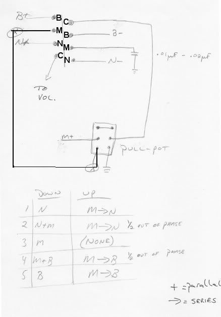 Has anyone checked the validity of this schematic. When i check each and every position, some seem to be incorrect. For instance: When the push-pull pot is in the "UP" position, the series connections (1/2 out of phase) is wrong. I don't want to get into a long and tedious outline of the wiring. If somebody else can check this wiring and confirm my findings, that would be great. Also, where is the Middle P.U "negative" or (M-)? Seems to be missing. Thanks guys (or Mike if you get to answer this?) Fenleo |
|
|
|
Post by UnklMickey on Dec 8, 2006 19:01:23 GMT -5
hi Fenleo,
welcome back.
i have never worked with that mod, but lots of guys here have.
i think ChrisK even re-drew it as a schematic.
i can't say for sure, but it seemed like there was more in Mike's drawing, than what you have here. maybe there was a later drawing?
cheers,
unk
|
|
|
|
Post by ChrisK on Dec 10, 2006 16:17:36 GMT -5
Phase means something else here. It's more of a description of the resulting sound instead of actual electrical phase between two pickups. In the #2 and #4 positions, the middle pickup is shunted by the cap in the series mode. In a parallel 1/2 out of phase combo, one pickup is commonly coupled to the other (and the output) by a series capacitor. This schematic is similar to the effect of the (Fender "special") cap used in the SSS S-1 Strats where the "special" cap is across either the bridge or neck pickup. It ain't exactly out of phase (as gn2 likes to define it) and the cap ain't exactly special, but the sound is distinctive. I do something very similar in this scheme; guitarnuts2.proboards45.com/index.cgi?board=schem&action=display&thread=1163395682where the special cap works as in the Fender SSS S-1 scheme. Both of these schemes are in essence a duality of each other. One uses the regular (pedestrian) Fender 5-way switch for 9 combos, and the other used the Schaller MegaSwitch "E" for 10 combos (HA!). If the cap is placed/used as in my scheme (selectively across the bridge or middle) using the Mike Richardson circuit, you will get 10 combos with the new one being the middle in series with the cap. Actually, I just wanted to come up with a scheme using the Schaller switches since they have the best mechanical feel IM (not so) HO. I guess I should probably "CAD-up" this MR scheme and post it in schematics. Wow, I can use the MegaSwitch "S"! It is (inferentially) connected to common (ground). |
|
fenleo
Rookie Solder Flinger
Posts: 10
Likes: 0
|
Post by fenleo on Dec 11, 2006 13:14:45 GMT -5
Chris K,
Thanks for the reply. I agree with you that the M- is most definitely grounded in this schematic.
Position #2 and #4 still confuse me. For example, in the "Up" position,
We get for POSITION #1: Neck and Middle P.U. IN SERIES-IN PHASE. This i understand.
We get for POSITION #2: Neck and Middle P.U. IN SERIES-IN PHASE BUT with cap in PARALLEL with the MIDDLE P.U.
I do not understand why Mike would call this "1/2 OUT OF PHASE". Out of Phase seems to be the wrong term here.
If anything, i would probably call POSITION #2: IN-SERIES-IN PHASE PARALLEL CAP.
Does anyone else have any thoughts on this. I'm i analyzing this correctly?
Thanks guys (and gals).
-fenleo-
|
|
|
|
Post by UnklMickey on Dec 11, 2006 13:47:54 GMT -5
hi Fenleo,
I AGREE.
the terms: "1/2 OUT OF PHASE" or "HALF PHASED". are "wobbly" and mis-leading.
"IN-SERIES-IN PHASE PARALLEL CAP" seems more appropriate.
or, in general, "PARTIALLY BYPASSED" or "HIGH-FREQUENCY BYPASSED" might be a reasonable description of the coil that has the parallel capacitor.
cheers,
unk
|
|
fenleo
Rookie Solder Flinger
Posts: 10
Likes: 0
|
Post by fenleo on Dec 11, 2006 15:04:09 GMT -5
Unklmickey,
Thanks for the quick reply. Now the million dollar question. What does a wiring like this (i am specifically referring to POSITION #2) do for your sound? Lets use simple laymans "bullsh%$it" terms (according to Bill Lawrence!)
For example, I agree POSITION #2 does give you the NECK IN SERIES-IN PHASE WITH THE MIDDLE P.U. (which given the output of each pickup would yield a rather powerful and full sound with no "quack"). ....but with the cap in parallel with the MIDDLE, what kind of sound would that give us.....?
This schematic is interesting at best, but what kind of TONAL output does it yield? In general, i know what pickups in PARALLEL and SERIES SOUND LIKE, but what kind of SOUND do you get when you put a capacitor IN PARALLEL with an entire pickup like Mike has in this schematic?
Thanks Unk!!!
--fenleo--
|
|
|
|
Post by UnklMickey on Dec 11, 2006 15:45:34 GMT -5
...Lets use simple laymans "bullsh%$it" terms (according to Bill Lawrence!)... okay. it all depends on the size of the cap. the smaller it is, the more it sounds like Neck * Middle. the larger it is, the more it sounds like just Neck (but with hum-cancelling if ONE of the 2 pickups are RWRP). somewhere in between those sizes, the top end should sound like Neck, and the bottom end should sound like Neck * Middle. also, i expect there will be a prominent peak caused by the cap's interaction with the Middle, but i can't predict what effect that will actually have, since this will have a moderate effect on the phase relationship with the Neck. and before you ask, i don't know what value would be appropriate to make it sound like Neck only. i will tell you, on a MIM strat, 22nF makes a nice upper midrange peak, when directly in parallel with a single pickup, or 2 pickups in parallel. (tone control at minimum). it definitely sounds a bit brighter than when the tone control is ALMOST at minimum. if i had to take a S.W.A.G., i'd say 0.5uF or 1uf. also, it you go TOO large, you will lose hum-cancelling too. maybe JohnH, or Channelman can do a Pspice sim. to give you an idea where to start. IMHO, partial bypass is definitely an idea worthy of experimention. cheers, unk |
|
|
|
Post by ChrisK on Dec 12, 2006 19:33:28 GMT -5
I made use of this capacitor-shunting in my implementation of this Mike Richardson scheme in a variable manner since I put one tone control directly across the bridge and the other directly across the neck; guitarnuts2.proboards45.com/index.cgi?board=schem&action=display&thread=1153172741What you get is the attenuation (and peaking) associated with a tone control across the one pickup with a high pass bypass path across that pickup for the other series connected one. The effect is a brighter tone with the wider harmonic range that results from the separate magnet windows of two pickups. Turning down my tone control across just one of the series chain made the response increasingly brighter. I found this capability most interesting when all three pickups were in a series chain. Holy tone dialing Batman. You mention the loss of "quack" is series modes. While I'm not sure what everyone means as to "quack", to me it's the wider sensing window coupled with the 1/2 octave higher resulting frequency response peak that results from the direct coupling of two similar generators/inductors in parallel. This tone cap or just cap paralleling gives back some of my "quack". The Fender SSS S-1 Strat uses this bypass idea and the MR scheme that I used as linked above sounds very like this when the applicable tone is turned down. I know explicitly since I A/B'd it against my Am Dlx Strats. I generally won't do a series mode design without this capability if at all possible. I used 0.022 uF for these caps with pleasing results. I used DiMarzio Virtual Vintage (stacked single coil sized humbuckers) pickups and am most pleased with the results. I tried Lace Alumitones in this scheme and was not impressed. Most likely because these are not your normal pickups, and the values of external components may have been wrong for best results. It may also have been due to an effect of my learned experience in that electrical out of phase is much more interesting using pickups that are not identical. The DiMarzio's were Heavy Blues, Vintage, and Blues bridge to neck. The Alumitone's were identical to each other. In retrospect, the resulting tone gets closer to the "parallel 1/2 out of phase" moniker attached to such schemes where one pickup was coupled to the other (and the output) thru a series cap (such as in the Jerry Donahue Tele) and several years back this was the description in vogue. While Mike's description does not comply with our current electrical definition, it was completely in step with its time. |
|
|
|
Post by ChrisK on Dec 16, 2006 0:05:59 GMT -5
|
|
|
|
Post by Mike Richardson on Dec 29, 2006 5:24:00 GMT -5
What is it that you don't understand? Yes, the M- was omitted. It should be grounded. With the pull pot down, you have normal Strat operation. With the pull pot up, in the bridge position the M+ connects to the B-, giving series operation. In the next position, you have the same connection, with the cap added in parallel with the bridge pickup, giving a different sound. In the middle position, the middle pickup is shorted to ground, thus you have a silent position. The next position is the middle and neck in series with the parallel cap, and finally the middle and neck in series.
|
|
fenleo
Rookie Solder Flinger
Posts: 10
Likes: 0
|
Post by fenleo on Jan 5, 2007 16:38:09 GMT -5
Mike,
I was merely inquiring about your Position #2 & #4 tones in the UP position. With no explanation, your notation of "1/2 out of phase" seemed a bit confusing to me.
Unklmickey and Chris K, thank you for your polite feedback on this one. Much appreciated.
--fenleo--
|
|


