|
|
Post by CheshireCat on Feb 15, 2006 14:42:33 GMT -5
Alright, I just figured out how to do photobucket, and here is the ultimate switching schematic that I could come up with. What do you guys think so far? I say "almost" because I am working on a phase inverter to put the bridge pickup out of phase when in the fourth position, being that the neck pickup is otherwise out of phase in all the other positions. Basically, I'll add that as a footnote when I get a chance. Also, what do you guys think of OOP on M & B combos? Incidentally, a great deal of thanks goes to Mike R's work, being that he has greatly inspired and influenced me. Also, this is based on a schematic that he did, tho I made some radical changes to it. That said, I personally go for the handdrawn aesthetic, just so long as it's clear and easy to follow. So, please, no BS about how I was too lazy to use MS Paint or something. That wasn't the case and I don't dig on that style. Important point: I didn't incorporate phase inverting nor splitting (or half-splitting) into the schematic. That's handled with seperate slider switches. I could have tried all this with a SuperSwitch and an 11-position Rotary Switch, but that would have been a nightmare to figure out, and ultimately I would be left with memorizing 55 different patches. All that for "greater simplicity". Don't think so. Chesh 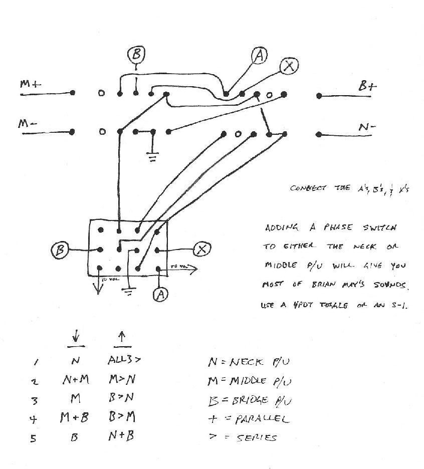 |
|
|
|
Post by UnklMickey on Feb 15, 2006 16:52:46 GMT -5
chesh,
could you clarify a few things for me?
what do B- and N+ connect to?
i assume the top switch is a 4-pole superswitch or rotary. do you number from the left or from the right?
thanks,
unk
|
|
|
|
Post by CheshireCat on Feb 15, 2006 17:57:20 GMT -5
chesh, could you clarify a few things for me? what do B- and N+ connect to? i assume the top switch is a 4-pole superswitch or rotary. do you number from the left or from the right? thanks, unk B- comes from ground. N+ goes to thru whatever splitters and phase inverters you want, and then to on to volume (or wherever else . . . vol, EQ, whathaveyou). The top switch is indeed a SuperSwitch, tho I suppose you could just as easily use a rotary switch if you so chose. I particularly prefer a SuperSwitch myself. It doesn't particularly matter which way the switch is oriented, just so long as you read the schematic correctly as related to the orientation of the switch. That said, the positions number 1-5 from right to left. Chesh |
|
|
|
Post by JohnH on Feb 15, 2006 18:45:31 GMT -5
Theres several things I like about this design:
In a guitar with three pickups, I think it is best to have one position where the five normal N, NM, M, MB, B settings can be found. There is too much weight of history behind that combo to ignore it.
The single toggle switch brings up the five best alternative options, and you have them in a logical order, getting steadily more powerful towards all three in series.
I would really want that phase switch, and despite Brian May (who has them on all his pickups), my favorite position is on the neck. In that position, it give access to BN out of phase, which is the best sounding and only humcancelling OoP option. Also, I find the neck is powerful enough to phase well with the other two pups when used with all three. On mine, it sounds like a banjo!
John
|
|
|
|
Post by CheshireCat on Feb 16, 2006 13:39:20 GMT -5
Theres several things I like about this design: In a guitar with three pickups, I think it is best to have one position where the five normal N, NM, M, MB, B settings can be found. There is too much weight of history behind that combo to ignore it. Indeed. Also, I wanted this to be as intuitive as possible. So, it only made sense that the first half should be straight Strat switching. The single toggle switch brings up the five best alternative options, and you have them in a logical order, getting steadily more powerful towards all three in series. Well, not only that, but notice how in positions 2 and 4, it's still N/M and M/B respectively, only it simply switches from parallel to series. I thought that kept things simple. As for the other positions, well, the only things left were both versions of N/B and something with all three pickups. I decided just to stick with ALL3 in series, using what would have been ALL3 in parallel to do N+B. I thought having two versions of ALL3 was kinda overkill, and I wanted to get the N/B combos in play. I would really want that phase switch, and despite Brian May (who has them on all his pickups), my favorite position is on the neck. In that position, it give access to BN out of phase, which is the best sounding and only humcancelling OoP option. Also, I find the neck is powerful enough to phase well with the other two pups when used with all three. On mine, it sounds like a banjo! Well, funny you mention it, because I do have a phase inverter as it is, it's just not pictured, nor are the splitters. They're there, and if I did a full schematic of everything on my guitar (which I probably will one day) then you'd not only see them, but a heck of a lot of other stuff. Interestingly enough, I'm working on a new phase inverter, probably something along the lines of a 4PDT slider switch to match the other DPDT sliders. Two of the poles would be the standard phase switch, which would invert the signal from the neck pickup, and the other two poles would turn on the power and route the signal from position four of the B+ pole on the SuperSwitch to an active phase inverter, much akin to the EMG-Pi2. The idea here is that phase inverting won't work in position four because the neck pickup is taken out of the picture and it's just down to the M/B combos. This way, regardless of what position I'm in, I'll have OoP. Chesh |
|
|
|
Post by ChrisK on Feb 16, 2006 18:42:53 GMT -5
I like it! Especially since you've retained as much of the logical position orientation like the Mike Richardson scheme. I believe that having electrical phase reversal on two PU's is critical (I use bridge and neck on the MR scheme that I did and love it.) Having phase switches on all PU's is redundant (you only need N-1 switches). It does require a 4PDT (I haven't looked to see if simplification is possible), so an S-1 is in order. BTW, the basis for the S-1 switch (a 4PDT alternate action pushbutton switch) IS available from Digikey. Let's see, a couple of standoffs, some holes in a pot shell, a concentric pot w/ the inner shaft converted to a push button....... Here’s the link rocky.digikey.com/scripts/ProductInfo.dll?Site=US&V=141&M=TL4201EEYAor just affix the switch under the PG. Or, one could look into adapting a regular PP pot w/ two DPDT sections. If you're going to buy a 4PDT toggle (~~$20), look into the 4 pole on-on-on version, the three positions might give you some new modes as well (with judicious pole wiring selection). |
|
|
|
Post by CheshireCat on Feb 16, 2006 18:59:34 GMT -5
I like it! Especially since you've retained as much of the logical position orientation like the Mike Richardson scheme. I believe that having electrical phase reversal on two PU's is critical (I use bridge and neck on the MR scheme that I did and love it.) Having phase switches on all PU's is redundant (you only need N-1 switches). Indeed. I don't even know if it's worth while to try and go to all the trouble to phase invert the bridge with M/B combos, but, then again, I didn't know if all the M/B combos were worthwhile, until all the Dire Straits fans sounded off.  It does require a 4PDT (I haven't looked to see if simplification is possible), so an S-1 is in order. Actually, a 4PDT on-on mini-toggle is pretty cheap I think. At least, I can get them cheap. BTW, the basis for the S-1 switch (a 4PDT alternate action pushbutton switch) IS available from Digikey. Let's see, a couple of standoffs, some holes in a pot shell, a concentric pot w/ the inner shaft converted to a push button....... Here’s the link rocky.digikey.com/scripts/ProductInfo.dll?Site=US&V=141&M=TL4201EEYAor just affix the switch under the PG. Or, one could look into adapting a regular PP pot w/ two DPDT sections. If you're going to buy a 4PDT toggle (~~$20), look into the 4 pole on-on-on version, the three positions might give you some new modes as well (with judicious pole wiring selection). Interesting. I'd like to definitely pursue this line of thinking. Chesh |
|
|
|
Post by CheshireCat on Mar 28, 2006 22:53:18 GMT -5
Okay guys (and gals),
Do any of you have any insights on my schematic in terms of tiddyness? Stuff like hanging from hot?
Chesh
|
|
|
|
Post by UnklMickey on Mar 28, 2006 23:48:52 GMT -5
Sorry Chesh,
even on a good day, i have trouble following the hand-drawn diagrams.
i just finished proof-reading some wiring and i'm all "googly".
i don't mean in the good, just click the button and find it in a flash kinda way.
i mean like "Marty Feldman Eyes".
unk
|
|
|
|
Post by sumgai on Mar 29, 2006 21:30:20 GMT -5
Chesh, The only 'hanging hot' I see is Position 1: the M+ is connected (via a jumper and circled-A) straight to the output, and the M- is connected to bupkis. Sorry, I don't see any way to avoid that one without screwing up other selections.  HTH sumgai |
|
|
|
Post by CheshireCat on Apr 3, 2006 18:38:42 GMT -5
Chesh, The only 'hanging hot' I see is Position 1: the M+ is connected (via a jumper and circled-A) straight to the output, and the M- is connected to bupkis. Sorry, I don't see any way to avoid that one without screwing up other selections. HTH sumgai Position 1? You mean the one on the left? Hmmmm . . . that's position 5, and, if I'm not mistaken, that doesn't figure into any Position 5 combo. I think that jumper might be a relic from a previous incarnation. I'll see about removing it. Post Factum: ah, now I see. Position 5 originally had an ALL3 in Parallel setting. I took out the M pickup, making it N+B. Okay, I'll remove that jumper. Any others? Chesh |
|
|
|
Post by sumgai on Apr 4, 2006 1:24:29 GMT -5
Chesh, OK, I get you now. I always start with pos. 1 to the left, you just started the other way around from me, tha's all. 'S OK, we're cool.   Checked the rest of it, no problems that I can see. ;D Removing the M+ jumper at pos. 5 will indeed remove the hanging hot. Otherwise, nice job, I had no problem dissecting the thing, once you clued me in about the numerical direction. sumgai |
|
|
|
Post by CheshireCat on Apr 4, 2006 2:20:15 GMT -5
Chesh, OK, I get you now. I always start with pos. 1 to the left, you just started the other way around from me, tha's all. 'S OK, we're cool. Checked the rest of it, no problems that I can see. ;D Removing the M+ jumper at pos. 5 will indeed remove the hanging hot. Otherwise, nice job, I had no problem dissecting the thing, once you clued me in about the numerical direction. sumgai Excellent, and WOW!! Coolness!! And here I was thinking that it was a massively jury-rigged set-up that probably has all sorts of loose ends and what not. Cool! Thank you so much!! So, how would it rank in terms of tiddyness, like, on a scale of 1 to 10 or something? Chesh |
|
|
|
Post by sumgai on Apr 4, 2006 15:04:02 GMT -5
Chesh, Messy. Sorry, gotta be honest.  I *think* it could be cleaned up, but that's for you to decide, it's your baby. ;D The only suggestion I might make would be to label each pole of both switches. This is something I've always had a bug up my buns about, clear labels for future reference when discussing bugs, features, whatnot. An easy example would be P1 for the first pole, etc. On a switch that has more than three terminals, lugs, whatever, a simple number by the first terminal would also be really nice, and it could double for a Position marker on a blade switch. For push-pull switches, an arrow in the right direction helps immensely. Toggle switches are only a bit harder, but the up/down arrows are at least helpful, unless the final orientation is obviously right and left. Rotated arrows to the rescue!  Just something to think about, if you're gonna invest some effort anyway in cleaning this thing up. Now that I think about it..... I'm a fine one to talk, I've been sitting on several diagrams that I have yet to post. Sorry if I've offended you (or anyone else) for this reason, I promise to get on the stick and start making my hand-scribbled notes into a coherent mess, RSN.  sumgai |
|
|
|
Post by CheshireCat on Apr 6, 2006 3:10:13 GMT -5
Chesh, Messy. Sorry, gotta be honest. I *think* it could be cleaned up, but that's for you to decide, it's your baby. ;D What do you mean "messy"? The actual wiring, or the way it looks in the diagram? (Assuming I remove the superfluous jumper on the M+ pole.) |
|
|
|
Post by sumgai on Apr 6, 2006 4:56:12 GMT -5
The drawing itself. Square it up, run straight lines, that kind of thing. As well as the labeling. If you can, try to devise routing that reduces the longer runs. Sometimes, that means using a circled letter to denote an undrawn connection. Those are OK only as a last resort, I personally prefer to see as few of them as possible. For instance, circled B could have been a drawn line, there would have been no crossovers. Also, another example: trace out the jumper from the 4P2T switch to M+1 to M-4 to B+3 to N-2/1, and back to the switch. I'd eliminate either the lead from the switch to M-4, or the one from N-2/1 back to the switch. They're both long, whereas a short jumper right on the switch between the approprate terminals would accomplish the same mission and look neater, or so I tend to think. And you might as well add the volume and tone pots and avoid the usual questions like "where do the pots go?" I can't tell about the actual wiring, I have no photos of it. ;D HTH sumgai |
|
|
|
Post by Mike Richardson on Apr 13, 2006 20:13:53 GMT -5
So why is it "almost" the ultimate? |
|
|
|
Post by ChrisK on Apr 13, 2006 23:01:16 GMT -5
I think that it's possibly WIP (work in progress?).
|
|
|
|
Post by CheshireCat on Apr 16, 2006 18:50:17 GMT -5
I think that it's possibly WIP (work in progress?). Indeed. Tho, if all goes well with this current line of inquery, I might be able to remove the "almost" qualifier and have what I think is indeed the ultimate. BTW, Mike, good to have you back. Think you might take the circuit for a spin and see if you find anything? Not necessarily prototype it, mind you, but just kinda give it a once over and tell me what you think. Ah. And you might as well add the volume and tone pots and avoid the usual questions like "where do the pots go?" Well, funny you should mention it. I don't use tone controls. I use onboard EQ, and all that plus the volume will come later down the chain. IOW, it's not integrated into the switching convention, but comes after it. I can't tell about the actual wiring, I have no photos of it. ;D I assume you're joking because this is in the design stages and the wiring hasn't been done yet. Chesh |
|
|
|
Post by sumgai on Apr 16, 2006 21:30:01 GMT -5
Chesh, Yep, it was an attempt at humor. But you did previously say: "What do you mean "messy"? The actual wiring, or the way it looks in the diagram?" From the word "actual", I made the obvious inference, even though you had already said that this was still in design mode. At that point, I must have thought to myself, "hey, let's have some fun with Chesh", and the rest, as they say, was history. I guess you had to be there, sorry if the joke fell flat.  But you're correct, this thing is a nice bit of work. Now, who's gonna prototype it first?  sumgai |
|
|
|
Post by CheshireCat on Apr 17, 2006 1:33:06 GMT -5
Chesh, Yep, it was an attempt at humor. But you did previously say: "What do you mean "messy"? The actual wiring, or the way it looks in the diagram?" From the word "actual", I made the obvious inference, even though you had already said that this was still in design mode. At that point, I must have thought to myself, "hey, let's have some fun with Chesh", and the rest, as they say, was history. I guess you had to be there, sorry if the joke fell flat. Well, at least you enjoyed it, and that's what's important. Incidentally, when I said "the actual wiring", I was more specifically refering to the "actual wiring convention", which the diagram was outlining. But you're correct, this thing is a nice bit of work. Thank you. That means a lot. So far; so good. Now, who's gonna prototype it first? Whoever is so moved to do so. Presumably it would be me, but if someone is so estatic that they want to make it this weekend's special project, be my guest. I am totally not above letting someone else be the guinea pig. That and the fact that I am still doing the rerout on my Utah. I just cleaned up a lot of routing from before, and am working on structural integrity issues, as well as neck alignment. I'm also going to be doing some interesting stuff with some epoxy and routing templates, and I also get to finish making the first of two custom pickups I'm working on. So, all that said, if someone else wants to put together the UUSS in my sted, be my guest and let me know how it turns out. To that end, I'm going to see about posting a cleaner version of the Schematic, but I must say I like the MR "font", if you will. Chesh |
|
|
|
Post by sumgai on Apr 17, 2006 12:27:24 GMT -5
Chesh, Ah, the foibles of the modern English language, in written form, and then posted on the innerweb.  (needs a 'sigh' smilie there) But I think we're both on the common ground now, and that can only benefit the whole forum. So, what's this about custom pickups?  sumgai |
|
|
|
Post by CheshireCat on Apr 17, 2006 14:40:23 GMT -5
Ah, the foibles of the modern English language, in written form, and then posted on the innerweb. (needs a 'sigh' smilie there) But I think we're both on the common ground now, and that can only benefit the whole forum. Indeed. So, what's this about custom pickups? Two of them: an ultrathin single coil to couple with one of the minihumbucker coils, to put some bass back into the neck position, which was lost from the displaced neck humbucker due to the addition of a Sustaniac; and a dedicated two pole pickup embedded in the neck that will run to an onboard octave divider, which will then create extended range options. Chesh |
|
|
|
Post by sumgai on Apr 18, 2006 1:19:34 GMT -5
Chesh, Pickup-in-fretboard.... that's some serious mod work. Didn't this topic come up once before here? Or did I see the idea get discussed somewhere else? You do, of course, plan on taking mucho pictures, right? ;D And a few 'tech' drawings too, they're always a nice touch. sumgai |
|
|
|
Post by CheshireCat on Apr 18, 2006 13:38:33 GMT -5
Chesh, Pickup-in-fretboard.... that's some serious mod work. Didn't this topic come up once before here? Or did I see the idea get discussed somewhere else? You do, of course, plan on taking mucho pictures, right? ;D And a few 'tech' drawings too, they're always a nice touch. sumgai Yes to all the above. The embedded pickup design was discussed in conjunction with the octave divider question. Pics and tech drawings will be forthcoming as I complete all this. Chesh |
|
|
|
Post by CheshireCat on Apr 27, 2006 13:51:24 GMT -5
Here's the improved upon schematic, without that superfluous jumper. I'm still figuring out the cleaner version in terms of clean lines and graphics. BTW, what software package do you guys use to do the CAD like schematics? CAD? Some version of it? I don't know if CAD is merely a generic term, or if it is also the name of a software package. The reason I ask is that if I am going to clean up the schematic, I want to do a proper job of it and make it look sharp. Chesh |
|
|
|
Post by Mike Richardson on Apr 27, 2006 18:51:41 GMT -5
I've been using TinyCad, which is free, which is why I use it. It has, among other things, the ability to use little green lines, which annoys Sumgai, which is why I use it. |
|
|
|
Post by CheshireCat on Apr 27, 2006 21:49:17 GMT -5
I've been using TinyCad, which is free, which is why I use it. It has, among other things, the ability to use little green lines, which annoys Sumgai, which is why I use it. Indeed. |
|
|
|
Post by UnklMickey on Apr 28, 2006 8:37:07 GMT -5
Yikes!
i wonder if Sumgai is shopping for asbestos underwear.
|
|
|
|
Post by Mike Richardson on Apr 28, 2006 14:54:15 GMT -5
Oh, for Pete's sake--it's just a joke. He offered some constructive criticism, and his points were valid. I'm still learning all of this drawing/schematic bidness, so I probably won't get it all down perfectly the first time. Or the next. Or, sad to say, the dozen or so after that. |
|


 I *think* it could be cleaned up, but that's for you to decide, it's your baby. ;D


 (needs a 'sigh' smilie there) But I think we're both on the common ground now, and that can only benefit the whole forum.