|
|
Post by JohnH on Nov 14, 2008 16:17:58 GMT -5
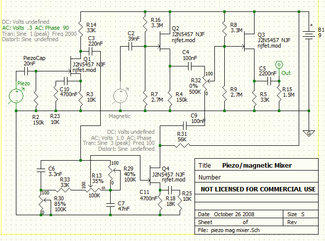
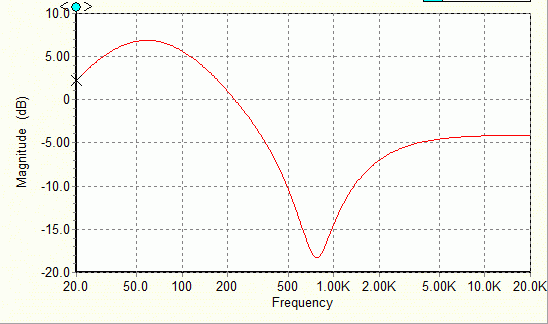
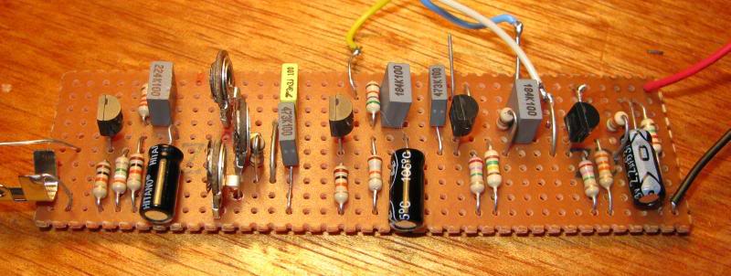
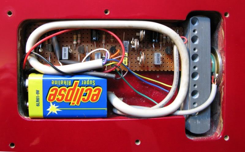
This thread is about adding a piezo pickup to a Strat style guitar to get acoustic style sounds. It's placed in the rear cavity between the trem block and the body. This post is a condensed version of this thread: guitarnuts2.proboards45.com/index.cgi?board=wiring&action=display&thread=3633&page=1Piezo ElementThe piezo device was from Jaycar in Australia, inside the plastic case (which I opened up and discarded) is a piezo transducer mounted on a thin brass disk: www.jaycar.com.au/productView.asp?ID=AB3440&CATID=15&keywords=&SPECIAL=&form=CAT&ProdCodeOnly=&Keyword1=&Keyword2=&pageNumber=&priceMin=&priceMax=&SUBCATID=291 Design Development Design DevelopmentIn developing the installation, I found initially that the raw sounds, even through a high-impedance buffer, were lacking in body with a big hump in the frequency response at around 700 to 1000 hZ. Heres a raw sample Its piezo only, first with no EQ, and then again played through a network of resistors and caps. Each has been normalized for level only. The buzzes come from it being strewn all over the desk with aligator clips: www.soundclick.com/bands/default.cfm?bandID=674084&content=songinfo&songID=6966415And here is a screen shot showing the sample trace, two spectrums, and also the RC network for the second sample modelled with Duncans ToneStack Calculator.  You can see the big hump around 700 to 1000hz, slightly suppressed in the second sample, but still evident, giving it a somewhat honky quality. Preamp I made a preamp design that included the RC network, with gain and mixing stages to blend in the magnetic pickups. Here's the schematic:  This is the frequency response when the blender is fully to the piezo:  The three presets in the tone network are roughly at the settings shown, giving a dip where I found it to be needed in my case. It still has an element of dobro/banjo type of sound which I'm happy to accept. I estimate that the raw piezo gives a signal about 10dB less than one of my relatively powerful single coils. So the piezo signal gets two gain stages, one to compensate for this lower output, and a second to boost it back up after the tone network. The mag signal is treated neutrally with zero gain. The whole output is then buffered again, and is capable of driving a PA line input or a guitar amp input. The magnetic input is taken after the volume and tone controls - any passive pickup wiring scheme could be used to combine magnetic pickups. The blending is with R32, and its seemless from full mag to full piezo - its really fun to play with and I've found some nice sounds with about 20/80 mag/piezo. One thing that surprised my with the piezo is that I did not need a very high input impedance, which I had read elsewhere was generally required. The piezo seems to act as a capacitor which generates voltages, and the specs say it is equivalent to 20nF. I found that an input impedance (R2) of 150k gave it a full bass sound, but then a roll off at lower frequencies to reduce unwanted sub-bass thumps. The current drain is about 0.35mA, so I'm hopeful of a few hundred hours use out of a battery. This is the construction, on stripboard:  It's sized to fit, with a battery, in the trem cavity which was empty. Hence I didn't need to build it to absolutely minimum size - it's much easier to have a bit of space on the board if possible. I found I needed to reverse all the mag pups, which helped phase combinations of mag and piezo. InstallationHere's the installation:  and a close up of the piezo 'short stack', showing the brass disk, with a coin under it and plastic packs on top, all fixed together with epoxy:  There's a single screened multicore cable that makes all the connections to the main cavity, for power control, mixer pot, magnet pups and output signals SoundsNow here are some samples, with other guitars for comparison: First some strums: www.soundclick.com/bands/default.cfm?bandID=674084&content=songinfo&songID=7044456This has: 1. An old Yamaha FG100 acoustic, recorded with a dynamic mic. A smallish bodied beginner guitar that I fixed up recently 2. A good Maton dreadought EM325C, recorded with mic as above - recently acquired 3. The Matons own piezo pickup recorded simultaneously with 2. 4. The new Strat piezo system, subject of this thread - full piezo 5. As 4, with a bit of neck magnetic pickup added 6. Strat bridge pickup And here's just the piezo: www.soundclick.com/bands/default.cfm?bandID=674084&content=songinfo&songID=7061284This one is more extensive, showing a range of sounds from the guitar, through a clean amp: www.soundclick.com/bands/default.cfm?bandID=674084&content=songinfo&songID=7102562 I’m finding it very useful playing in our covers band since it helps me get whatever sound is needed out of one guitar. EDIT 09/10/11 Heres another sample, with me attempting the intro from 'Dear Prudence' www.soundclick.com/bands/page_songInfo.cfm?bandID=674084&songID=11118334It starts with all magnetic, with a series combo of N and M, then at 10 sec, the piezo mixes in, and at 23, it is pure piezo cheers John |
|
|
|
Post by JohnH on Nov 29, 2008 3:51:08 GMT -5
Additional sound file added to the post above, with a range of sounds from this guitar using mag and piezo pickups:
John
|
|
|
|
Post by dennyb2009 on Jul 10, 2009 20:56:28 GMT -5
Thanx for the piezo info The examples you put up sound good and your description was great . Still I will have to think hard about adding a piezo under the bridge when I build that 12 string !
|
|
|
|
Post by irwired on Sept 17, 2010 15:56:49 GMT -5
Has anyone had experience with passive pezio pickups?   I have run across them on big box music store sights. |
|
|
|
Post by ashcatlt on Sept 17, 2010 17:26:32 GMT -5
The piezo pickup itself is a passive device. The active electronics are there partly to help it play nice with the magnetic pickups, and partly for tone shaping.
|
|
|
|
Post by JohnH on Oct 8, 2011 16:56:01 GMT -5
|
|
boctok
Rookie Solder Flinger

Posts: 18 
Likes: 0
|
Post by boctok on Jun 30, 2014 12:13:43 GMT -5
JohnH,
I was curious to find out how you connected all of this to the existing electronics in the guitar (i.e. the existing volume and tone pots).
I understand how both pickups were wired to the board, but I'm not getting how the preamp/blending circuit was connected to the volume and tone pots, or did you bypass those altogether?
I was hoping to reproduce the circuit but keep the existing volume and tone controls.
I'm actually making a "Cigar Box Guitar" with one single coil at the neck and a piezo bridge pickup. I was going to try to have one master volume, one master tone (maybe two, if needed) and one pot for blending.
Your insight would be greatly appreciated!
|
|
|
|
Post by JohnH on Jun 30, 2014 15:21:08 GMT -5
Hi boctok and welcome to GN2.
What you describe should work out fine. On the circuit diagram, the signal source labelled as 'magnetic', feeding into C2 and transistor Q2, actually represents the output from the full magnetic pickups switching and volume/tone circuit. So it comes from the volume control centre lug, where it would normally be going to the jack. Any normal guitar wiring could work. So overall, you set up the magnetic tone and volume, then mix in however much peizo you want, which blends from a 0/100% mix, to 50%/50% to 100%/0. There's no overall master volume, but there is enough controls to get any blend or volume you want. eg If you only want pure piezo, then turn the magnetic volume to zero, and now the blend control is acting like a volume for piezo. Then maybe add a touch of magnetic to that, etc.
Be prepared for considerable tweaking to get the tone and relative levels right, but it is a very tweakable circuit so it should be a suitable basis. Good luck and thankyou for your interest.
|
|
boctok
Rookie Solder Flinger

Posts: 18 
Likes: 0
|
Post by boctok on Jul 2, 2014 6:29:47 GMT -5
|
|
|
|
Post by JohnH on Jul 2, 2014 7:52:44 GMT -5
It might be possible. But why would it be better? The simple linear pot used in this design works very well and gives smooth controllable blends. I think those dual-gang blenders are intended to blend between passive pickups rather than in an active circuit like this. I would expect that wired in this circuit, the blend would move all one way as soon as you move away from the centre |
|
boctok
Rookie Solder Flinger

Posts: 18 
Likes: 0
|
Post by boctok on Jul 2, 2014 9:12:22 GMT -5
Okay, thanks!
Also, I'm having some difficulty finding the N-JFETs listed in your schematic. Any substitutions that would be a direct exchange?
Nevermind, I found some.
|
|
|
|
Post by JohnH on Jul 2, 2014 15:17:25 GMT -5
I had a thought about the circuit:
One of the main things it does is to amplify the level from the piezo so that it matches the magnetic. The design shown is where I ended up after adjusting components for my set-up. There are two resistors R23 and R25 which set the amplification for the piezo signal. The lower they are, the higher the gain. So you may want to allow to vary them to suit your build. One way would be to make them each a 50k trimpot instead of a 10k resistor.
|
|
boctok
Rookie Solder Flinger

Posts: 18 
Likes: 0
|
Post by boctok on Jul 7, 2014 5:21:55 GMT -5
So, correct me if I'm wrong, but to replace the resistors with a trim pot, I would tie one of the side lugs to the center lug and use that as one side of the circuit and the other side lug as the other side of the circuit. Or just one of the side lugs and the center lug, leaving the remaining side lug unconnected?
|
|
|
|
Post by JohnH on Jul 7, 2014 15:54:16 GMT -5
Either of those is fine
|
|
boctok
Rookie Solder Flinger

Posts: 18 
Likes: 0
|
Post by boctok on Jul 17, 2014 13:18:50 GMT -5
From the picture of the stripboard, I see that you used mostly film capacitors, but that three are electrolytic. What effect would using one or the other have on the circuit? I've always been told that film capacitors are the standard in audio circuits, but that doesn't mean that I haven't seen electrolytics as well as ceramics in various combinations in many audio devices. Also, would it make much of a difference at this low power?
Thanks for all your help.
|
|
|
|
Post by newey on Jul 17, 2014 14:03:24 GMT -5
boctok-
I'll let JohnH provide you with the definitive answer here, but I note that none of the capacitors on his schematic is shown as being an electrolytic type, in that none is shown with a "+" to designate the polarity. Where an electrolytic type is required in a design, the polarity has to be identified, in order to avoid a rapid failure (often, a fairly dramatic failure as well . . .) of an electrolytic cap wired wrong way around.
So, based on that, I suspect that JohnH will tell you that he just used those because he had those available in the correct values, not because the design required electrolytic ones. But again, we'll await a definite answer from John.
As far as film vs. ceramic, I doubt there is a reason to prefer one over the other in this type of a circuit.
|
|
|
|
Post by JohnH on Jul 17, 2014 14:52:07 GMT -5
I used electros for C5, C10 and C11, because of their larger values. They work fine, so long as their negative ends go to ground (or to output for C5)
|
|
boctok
Rookie Solder Flinger

Posts: 18 
Likes: 0
|
Post by boctok on Aug 12, 2014 11:18:40 GMT -5
I wanted to use a 1/4" stereo plug as a sort of on/off switch, so that when the guitar is unplugged, the preamp won't be "on". Is this how it should be wired up? I have the audio "output", going to the tip, the neg lead from the 9V battery going to the base and the ring going to what would have connected to the neg 9V lead.  |
|
|
|
Post by sumgai on Aug 12, 2014 12:20:33 GMT -5
boctok, Welcome to The NutzHouse!  In theory, what you've drawn is electrically correct. However, we consider it "bad form" to make the circuit's signal ground depend on the power ground by forcing it through the ring-to-sleeve physical connection. Only at the output jack sleeve (what you called the base) should they meet, for conduit via the guitar cable to the amp. (Or some effects pedals, etc.) It's best that you swap the ring and sleeve terminals so that the battery neg terminal goes to the jack's ring terminal, and the circuit ground is going to the jack's sleeve. The concept here is that signal ground, shield ground, and power ground are all different things within a circuit, and none of them should physically depend on either of the others. I know that's hard to understand at first, and if you're not clear about it, just ask - that's why we're here, to help explain the Nutz & Boltz of what's under the hood!  HTH sumgai |
|
|
|
Post by JohnH on Aug 12, 2014 15:10:29 GMT -5
I agree battery negative should go to the ring, its just more normal that way. Not that anything bad is likely if it was the other way around, since either way, with plug out, nothing is happening and with plug in, all grounds are connected.
|
|
|
|
Post by newey on Aug 12, 2014 18:07:19 GMT -5
It occurs to me that putting the 9V- to the ring instead of to the sleeve does offer a slight advantage in those applications where one has passive pickups with an active preamp, or with those active pickups that can also be used as passives. By using a stereo cable, the guitar can be used passively and the battery stays disconnected.
|
|
boctok
Rookie Solder Flinger

Posts: 18 
Likes: 0
|
Post by boctok on Aug 13, 2014 10:38:38 GMT -5
boctok, Welcome to The NutzHouse!  In theory, what you've drawn is electrically correct. However, we consider it "bad form" to make the circuit's signal ground depend on the power ground by forcing it through the ring-to-sleeve physical connection. Only at the output jack sleeve (what you called the base) should they meet, for conduit via the guitar cable to the amp. (Or some effects pedals, etc.) It's best that you swap the ring and sleeve terminals so that the battery neg terminal goes to the jack's ring terminal, and the circuit ground is going to the jack's sleeve. The concept here is that signal ground, shield ground, and power ground are all different things within a circuit, and none of them should physically depend on either of the others. I know that's hard to understand at first, and if you're not clear about it, just ask - that's why we're here, to help explain the Nutz & Boltz of what's under the hood!  HTH sumgai Actually, that makes perfect sense. I didn't really think about it because I was more focused on having the ability to turn off the preamp/blend circuit. Thanks for pointing it out.  |
|
|
|
Post by sumgai on Aug 13, 2014 12:36:23 GMT -5
boctok, Yer welcome!  John is correct in that your way will work, but the point of all this is, we strive to reduce the number of possible failure points. In your case, forcing signal ground through a second connection, ring-to-sleeve instead of straight to sleeve, would be a possible point of failure. The problem would be hard to spot, because the battery would have enough juice to force the current through the connection, but the signal wouldn't. Trust me, I've seen this before - it's why people like me go bald before their time!  |
|
boctok
Rookie Solder Flinger

Posts: 18 
Likes: 0
|
Post by boctok on Aug 14, 2014 8:22:46 GMT -5
Well, preliminary tests look good. Everything is functioning as it should. I still need to play with the trim pots a bit to dial in the levels. There is quite a bit of hum, partly because I'm using a single coil, but there is additional hum when I bring in the piezo. I was also sitting about 3' from the amp. No pops or difference in hum when I touch the strings. The strings would be a bit of work to ground, because they all run through separate ferrules in a wooden tailpiece, to the piezo bridge. The bridge is brass. JohnHQ1: Did you ground the blend pot? I ran a small copper wire from the back of the other pots to the blend. This was before I tested, so I don't know what difference there is had I not done so. Hum dissipates greatly when I touch the 1/4" jack, which leads me to believe that something is not right in the grounding. Q2: Shielding the circuit board - as an extra measure, what do you think about using a small ESD bag around the circuit board. I have all of the connections insulated, so there would be no danger of a short from the board. |
|
|
|
Post by JohnH on Aug 14, 2014 15:11:07 GMT -5
Many congratulations to have got it going!
On my system (I just plugged it in to check), I get no hum when its blended fully to piezo but the top becomes 'alive' to taps and scrapes etc and there is a very slight hiss evident if I turn up amp gain. I get normal single-coil hum on the magnetic pickup. The pots are all with cases grounded, just because mine is a Strat arrangement. I have foil under the pickguard but not the whole cavity on this guitar. But I think the idea of the shielding bag is a good one to try, so long as you can insulate from it. It would need the conductive part of the bag to be grounded i think.
On electric guitar, grounding the strings is a key element, and what it does is ground the player. It makes a big difference, as you can see when you touched the jack ground. Finding a way to do that in your case is worth some thought.
You'll be into tweaking it now to get the tone how you want it. How are the relative levels of mag and piezo as you pan between them?
On the three presets, you can set the tone of the piezo. One is basically a low pass filter, and it sets a bass frequency above which it rolls off. The third is a high pass filter which rolls off below a treble frequency that you set, and the second middle one mixes between these two and sends the result onward. So to set a mid scoop, you make the two filter frequencies with a gap in the middle, or if they overlap, you get a mid hump. Then turn the second preset to emphasise bass or treble according to taste. Once you have your head around what these presets are doing, you can build in quite a versatile preset EQ profile, given its just a simple circuit. Its based on a system used in some stomp boxes.
|
|
boctok
Rookie Solder Flinger

Posts: 18 
Likes: 0
|
Post by boctok on Aug 19, 2014 11:51:59 GMT -5
Oddly enough, after adding the rest of the strings to make adjustments to the nut and bridge, the noise was gone. I didn't have everything secured inside the box when I did the initial testing of the circuit, so something must've been shorting. I suspect that the negative from the piezo was touching something, because it is the uninsulated, braided lead wrapped around the positive and there is a bit of slack to allow opening the box for battery changes etc.
I'm amazed at the sound. Thanks for posting the schematic.
|
|
|
|
Post by JohnH on Aug 19, 2014 15:25:47 GMT -5
That's good news. Any chance of pics or sound clips? I'm also curious about your piezo, was it similar to the one I used or different? and did the circuit need much tweaking?
btw, If you want to try sound clips, now that you have this preamp going, it will plug straight into several types of things, including amps, mixer line-ins or pc sound card line-ins.
|
|
boctok
Rookie Solder Flinger

Posts: 18 
Likes: 0
|
Post by boctok on Aug 21, 2014 20:12:58 GMT -5
I'm still tweaking the bridge height, looking for the best possible action. I have the nut set and the frets are all level. The piezo is an under saddle. It resembles an acoustic bridge, but the bridge piece is brass. I'm going slow with it, just taking off a little at a time. I don't want string buzz. I'll try to get some pictures posted and as soon as I get everything set, I'll post a sound clip. I also made a small 5 watt cigar box amp to go with it. I'll post those pictures too.
I saw a review recently by Rob Chapman on a guitar with a "Fishman Powerbridge", which sounds much like these. Basically an under saddle transducer with a preamp.
|
|
boctok
Rookie Solder Flinger

Posts: 18 
Likes: 0
|
Post by boctok on Apr 24, 2016 18:08:30 GMT -5
Sorry for what is probably an elementary question, but in this circuit, where it calls for the variable resistors @ 85%, 40% and 35%, can a fixed resistor be substituted that is say 85% of 100K (~85K)?
I guess what I'm asking is, is the value of a 100K variable resistor @ 85% = 85K?
|
|
|
|
Post by JohnH on Apr 24, 2016 18:44:28 GMT -5
Sorry for what is probably an elementary question, but in this circuit, where it calls for the variable resistors @ 85%, 40% and 35%, can a fixed resistor be substituted that is say 85% of 100K (~85K)? I guess what I'm asking is, is the value of a 100K variable resistor @ 85% = 85K? No problem. Yes you can use fixed resistors. But the way my software drew those pots, and the way I wired them there would imply that, at 85%, the value needed as a fixed resistor is 100-85=15 %. You can see the '0' and '100' ends marked on the diagram, and in two cases, my schematic shorts out between the wiper (say 85% or as marked_ and 0%. Note that R13 would need two fixed resistors. But that part of the circuit was intended to allow tweaking of the tone, to try to set a general balance that I liked. So I used preset pots (see photo), and Id advise to use them too if you are doing something similar, since your set up would be different. |
|


